EP4411090A1 - Conteneur pour modules électroniques d'une source d'énergie régénérative et installation comprenant le conteneur - Google Patents
Conteneur pour modules électroniques d'une source d'énergie régénérative et installation comprenant le conteneur Download PDFInfo
- Publication number
- EP4411090A1 EP4411090A1 EP23155230.8A EP23155230A EP4411090A1 EP 4411090 A1 EP4411090 A1 EP 4411090A1 EP 23155230 A EP23155230 A EP 23155230A EP 4411090 A1 EP4411090 A1 EP 4411090A1
- Authority
- EP
- European Patent Office
- Prior art keywords
- container
- container according
- chambers
- electronic components
- side walls
- Prior art date
- Legal status (The legal status is an assumption and is not a legal conclusion. Google has not performed a legal analysis and makes no representation as to the accuracy of the status listed.)
- Pending
Links
Images
Classifications
-
- H—ELECTRICITY
- H05—ELECTRIC TECHNIQUES NOT OTHERWISE PROVIDED FOR
- H05K—PRINTED CIRCUITS; CASINGS OR CONSTRUCTIONAL DETAILS OF ELECTRIC APPARATUS; MANUFACTURE OF ASSEMBLAGES OF ELECTRICAL COMPONENTS
- H05K7/00—Constructional details common to different types of electric apparatus
- H05K7/20—Modifications to facilitate cooling, ventilating, or heating
- H05K7/20536—Modifications to facilitate cooling, ventilating, or heating for racks or cabinets of standardised dimensions, e.g. electronic racks for aircraft or telecommunication equipment
- H05K7/20554—Forced ventilation of a gaseous coolant
- H05K7/2059—Forced ventilation of a gaseous coolant within rooms for removing heat from cabinets, e.g. by air conditioning device
-
- E—FIXED CONSTRUCTIONS
- E04—BUILDING
- E04H—BUILDINGS OR LIKE STRUCTURES FOR PARTICULAR PURPOSES; SWIMMING OR SPLASH BATHS OR POOLS; MASTS; FENCING; TENTS OR CANOPIES, IN GENERAL
- E04H5/00—Buildings or groups of buildings for industrial or agricultural purposes
- E04H5/02—Buildings or groups of buildings for industrial purposes, e.g. for power-plants or factories
- E04H5/04—Transformer houses; Substations or switchgear houses
-
- H—ELECTRICITY
- H05—ELECTRIC TECHNIQUES NOT OTHERWISE PROVIDED FOR
- H05K—PRINTED CIRCUITS; CASINGS OR CONSTRUCTIONAL DETAILS OF ELECTRIC APPARATUS; MANUFACTURE OF ASSEMBLAGES OF ELECTRICAL COMPONENTS
- H05K7/00—Constructional details common to different types of electric apparatus
- H05K7/14—Mounting supporting structure in casing or on frame or rack
- H05K7/1485—Servers; Data center rooms, e.g. 19-inch computer racks
- H05K7/1497—Rooms for data centers; Shipping containers therefor
Definitions
- the invention relates to a container for electronic components of a renewable energy source and a system for operating a renewable energy source in the form of a solar system.
- Renewable energy sources are being used more and more and are an important part of achieving climate goals to reduce CO2 emissions.
- roofs of industrial plants or production halls are also being fitted with solar panels. The energy generated in this way can be fed into the local power grid via transformer stations. It has also proven to be a good idea to use batteries as temporary storage.
- Lithium-ion or iron-phosphate batteries are currently used for this purpose, some of which are also provided with appropriate temperature control.
- the prescribed temperatures for servers and battery storage units, for example, are often room temperature, i.e. between 20 °C and 25 °C.
- fire resistance class F 90 fire resistance duration 90 minutes
- these types of batteries are very difficult to extinguish, so that even if the fire brigade is called out in good time, the adjacent buildings and inventory can still be seriously damaged.
- these energy storage units are deliberately left to burn down in the event of a fire. Building them separately and located outside the company premises is a very costly solution. In addition, flexibility is limited, e.g. if the building should be relocated.
- the components When used in transformer stations, the components are manufactured using conventional concrete technology and are therefore expensive. The components are thick-walled and heavy, so special transport vehicles are required to deliver the Building parts or the prefabricated station must be installed. Pre-installation is also hardly possible, as these stations are usually only finally assembled at the installation site.
- the solar inverter comprises a capacitor bank with one or more capacitors for maintaining an intermediate circuit voltage, a converter for converting the intermediate circuit voltage to an alternating current voltage, and a coil box connected between the converter and the alternating current output.
- the coil box contains one or more inductors, is mounted in the second zone, has connections to the converter that are accessible to the first zone, and is otherwise separated from an outer casing of the first zone by an air gap.
- the US 8 482 163 B2 describes an inverter unit comprising an enclosure, an inverter within the enclosure, and a cooling source in thermal communication with the inverter, the inverter having a rated output power at a first temperature and the cooling source configured to maintain the inverter at or below a second temperature sufficient to enable the inverter to be overdriven to increase the output power by 5% or more above the rated output power in response to sensed load and temperature conditions.
- a power electronics system having an environmentally sealed electronics compartment for housing power electronics equipment.
- the system includes a plenum within the sealed electronics compartment for air circulation.
- a first liquid cooling circuit is configured to cool air flowing through the plenum.
- a second liquid cooling circuit is configured to directly cool the power electronics equipment.
- the system includes a controller configured to independently control the flow rate of the first liquid cooling circuit and the second liquid cooling circuit.
- a container for electronic components, in particular a renewable energy source or a computer system, comprising side walls with at least one door for access to the interior of the container, a floor element and a ceiling element, wherein the interior of the container is divided into two chambers separated by a partition wall, wherein the two chambers have differently adjustable permissible temperature ranges via at least one air conditioning unit, wherein at least the side walls have an inner cover layer and an outer cover layer made of electrically conductive material, preferably sheet steel or aluminum sheet, and a foam core, preferably made of polyurethane, for thermal insulation, wherein the electronic components are arranged along a corridor in the interior of the chambers.
- a renewable energy source or a computer system comprising side walls with at least one door for access to the interior of the container, a floor element and a ceiling element, wherein the interior of the container is divided into two chambers separated by a partition wall, wherein the two chambers have differently adjustable permissible temperature ranges via at least one air conditioning unit, wherein at least the side walls have
- the container according to the invention is composed of side walls which are designed similarly to a refrigerated box of a refrigerated vehicle with an inner covering layer and an outer covering layer made of metal, between which a foam core is inserted so that a high level of thermal insulation can be achieved.
- the container is completed by a floor element and a ceiling element which, like the side walls, can also be made of foam.
- the container can be designed in terms of its external dimensions so that it can be loaded onto a trailer or low-loader which can be driven on public roads without special heavy transport markings.
- the container can also be easily moved to another location using an appropriate fastening device.
- the electronic components can also be at least partially fitted in advance inside the container.
- an externally connectable fire extinguishing water device is provided for flooding the container.
- the required water pipe can be operated at a greater distance from the container, so that there is no danger to firefighters due to fire flashover. It is particularly advantageous if a liquid-tight floor pan is provided to collect decontaminated extinguishing water. Any cable or line ducts introduced from the outside are also made liquid-tight, which can be done easily with PU foam, for example.
- the container itself can be set up in such a way that a minimum distance to a building is maintained, which can typically be 5 m for fire flashover. In this way, any mandatory fire resistance class for the walls of the container is also eliminated, which reduces manufacturing costs.
- the two chambers enable a spatial separation of the electronic components with regard to their power output.
- Two temperature ranges are formed inside the container, so that electronic components with different requirements regarding their temperature range can be housed in separate chambers.
- battery storage for a solar system in a chamber that has a narrower temperature window, for example between 20 °C and 25 °C.
- Inverters or other electronic components for operating the solar system could then be arranged in the other chamber.
- a server can be housed in one chamber, while the other chamber is filled with a battery storage system to ensure continued operation of the server in the event of a power outage.
- the temperature ranges of the chambers can be controlled via a two-evaporator system or via a one-evaporator system and a fan arrangement.
- This air conditioning unit can have a one or two evaporator system for separate air conditioning of each chamber.
- a fan controlled by a thermostat can be provided in the dividing wall. This can significantly reduce energy consumption, as only the battery storage or other temperature-sensitive components (servers, etc.) must be operated within a prescribed temperature range (usually +20 degrees to +25 degrees Celsius).
- a prescribed temperature range usually +20 degrees to +25 degrees Celsius.
- the outside temperature is warm, air is blown from the air-conditioned chamber into the other chamber until the desired temperature of the second chamber is reached.
- warm air can be blown from the warm, non-air-conditioned chamber into the first chamber.
- the temperatures are favorable, the air conditioning system does not need to be used at all.
- the partition wall is provided with a lockable access opening to allow access to both chambers or an escape route via the door.
- the partition wall can be equipped with a sliding door or swing door as an access opening.
- two doors are provided on opposite sides of the container to allow access to both chambers or an escape route.
- both chambers can be reached even without a through door in the partition wall.
- an intermediate floor is introduced which rests on a support structure and on which the electronic components are arranged.
- the area under the intermediate floor can serve as a cable feed via at least one opening in the side wall. It is advantageous if several openings are provided on the side walls, which are preferably arranged mirror-symmetrically or rotationally symmetrically to one another on the side walls.
- the container can be designed with a raised floor, which allows high-voltage cables to be laid and fed into the container in the ground. This means that the high-voltage cables are particularly protected, as no cables need to be laid above ground.
- the insulated side walls are made of conductive sheet metal inside and out. This can be used as earthing for potential equalization
- a roof hatch made of a plastic material is arranged in the roof element.
- roof hatch spans the partition wall, with the area between the partition wall and the roof hatch being filled with an insulation panel.
- the roof hatch is mounted as a pressure equalization flap, which can be used in the event of a possible explosion.
- a system for operating a renewable energy source in the form of a solar system comprising a transformer station for connection to the power grid and a free-standing container as described above, in which a battery storage unit is installed in the first chamber with a narrow temperature range and at least the inverters for operating the solar system are arranged in the second chamber with a wider temperature range.
- connection of a solar system via the transformer station is realized by means of the container according to the invention, so that the electronic components required for operation can be arranged in a thermally insulated area.
- the container has a predetermined minimum distance from buildings.
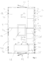
- FIG. 1 an embodiment of a container 2 according to the invention is shown in a side view.
- the container 2 has two longer side walls 4 along the long side and two shorter side walls 6 along the short side.
- the side walls 4 and 6 are each constructed with an inner cover layer 8 and an outer cover layer 10, between which a foam core 12 is attached for thermal insulation.
- a door 14 is attached to each of the two shorter side walls 6.
- a partition wall 16 divides the interior of the container 2 into a warmer chamber 18 and a colder chamber 20. Lighting fixtures 22 and fire detectors 24 for the two chambers 18 and 20 can also be arranged on the ceiling. A roof hatch 26 is also provided which spans the partition wall 16.
- the colder chamber 20 is provided with an air conditioning unit 28 which leads conditioned air 30 into the interior of the colder chamber 20. An air flow can also be led into the warmer chamber 18 via a fan unit (not shown) in the partition wall 16.
- passages 32 are provided in the side walls 4, which are arranged in a mirror-symmetrical or rotationally symmetrical manner, so that the container 2 can be connected to an adjacent container in different ways or can be connected to other units depending on the orientation of the container 2.
- an extinguishing water connection 34 is provided, via which extinguishing water can be fed into the interior of the container 2 in the event of a fire.
- the container 2 is equipped in such a way that electronic components are inserted into the two chambers 18 and 20 depending on the working temperature.
- several battery storage units 36 and a control unit 38 are installed in the colder chamber 20.
- Battery storage units 26 usually have to be operated in a narrower temperature window, for example between 20 °C and 25 °C, in order to meet the manufacturer's specifications.
- the chamber 20 was therefore designed in terms of its air conditioning so that this requirement can be met.
- inverters 40 that are connected to a solar system can be installed in the warmer chamber 18.
- the inverters 40 typically have a higher power loss, so that the warmer chamber 18 can meet different requirements with regard to its air conditioning than is the case with the battery storage 36.
- the installation location of the electronic components can be selected so that optimal working conditions are achieved for each component.
- partition wall 16 it would also be possible to design the partition wall 16 to be removable or to equip the container 2 without the partition wall 16.
- the area between the partition wall 16 and the roof hatch 26 can also be sealed with appropriate insulation material.
- the two oppositely arranged doors 14 define a corridor that can be entered by service personnel.
- the electronic components are arranged along the corridor in such a way that passage is possible at any time.
- the electronic components are preferably stored in control cabinets on the side walls 4.
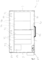
- FIG. 1 The structure of container 2 shown in Figure 2 shown again in a side view.
- FIG. 2 The structure of container 2 shown in Figure 2 shown again in a side view.
- Figure 2 It can be seen that the electronic components in the form of the inverter 40, the battery storage 36 and the control unit 38 are arranged on an intermediate floor 42, which rests above the bushings or opening 32 on a framework (not shown).
- the framework in turn is arranged on a floor element 44, which forms the lower end of the container 2.
- a roof element 46 is attached to the top, which has the roof hatch 26. High-voltage lines can be fed in or out via the bushings 32.
- the area below the intermediate floor 42 is usually sunk into the ground. This area, which is in Figure 2 provided with the reference number 48, can also form a watertight floor pan in which contaminated extinguishing water is collected, which was supplied via the extinguishing water connection 34 in the event of a fire.
- the roof hatch 26 acts as a pressure equalization flap, which can be used in the event of a deflagration.
- the container 2 can be used in a system for operating a renewable energy source in the form of a solar system, which has a transformer station for connection to the power grid.
- the transformer station can be the free-standing container 2 as described above, in which the battery storage 36 is installed in the first chamber 20 with a narrow temperature range and at least the inverters 40 for operating the solar system are arranged in the second chamber 18 with a wider temperature range.
- a server can be provided in the second chamber 18, which can be supplied via the battery storage 36.
- Container 2 has external dimensions that allow it to be transported on public roads.
- the width along the transverse side is therefore slightly less than 3 m, the total length along the long side is approximately 5 m.
- the height is less than 3 m.
Landscapes
- Engineering & Computer Science (AREA)
- Architecture (AREA)
- Microelectronics & Electronic Packaging (AREA)
- Computer Hardware Design (AREA)
- General Engineering & Computer Science (AREA)
- Power Engineering (AREA)
- Civil Engineering (AREA)
- Structural Engineering (AREA)
- Aviation & Aerospace Engineering (AREA)
- Physics & Mathematics (AREA)
- Thermal Sciences (AREA)
- Casings For Electric Apparatus (AREA)
Priority Applications (1)
| Application Number | Priority Date | Filing Date | Title |
|---|---|---|---|
| EP23155230.8A EP4411090A1 (fr) | 2023-02-06 | 2023-02-06 | Conteneur pour modules électroniques d'une source d'énergie régénérative et installation comprenant le conteneur |
Applications Claiming Priority (1)
| Application Number | Priority Date | Filing Date | Title |
|---|---|---|---|
| EP23155230.8A EP4411090A1 (fr) | 2023-02-06 | 2023-02-06 | Conteneur pour modules électroniques d'une source d'énergie régénérative et installation comprenant le conteneur |
Publications (1)
| Publication Number | Publication Date |
|---|---|
| EP4411090A1 true EP4411090A1 (fr) | 2024-08-07 |
Family
ID=85199222
Family Applications (1)
| Application Number | Title | Priority Date | Filing Date |
|---|---|---|---|
| EP23155230.8A Pending EP4411090A1 (fr) | 2023-02-06 | 2023-02-06 | Conteneur pour modules électroniques d'une source d'énergie régénérative et installation comprenant le conteneur |
Country Status (1)
| Country | Link |
|---|---|
| EP (1) | EP4411090A1 (fr) |
Citations (9)
| Publication number | Priority date | Publication date | Assignee | Title |
|---|---|---|---|---|
| US5735639A (en) * | 1996-12-13 | 1998-04-07 | The United States Of America As Represented By The Secretary Of The Navy | Modular mobile safety structure for containment and handling of hazardous materials |
| US5761854A (en) * | 1993-07-19 | 1998-06-09 | Weatherhaven Resources, Ltd. | Collapsible portable containerized shelter |
| DE10142103A1 (de) * | 2000-08-31 | 2002-06-06 | Betonbau Gmbh | Raumzelle zum Schutz einer Senderanlage oder anderer elektrotechnischer Geräte für die Telekommunikation sowie Verfahren zur Klimatisierung der Raumzelle |
| US8482163B2 (en) | 2009-05-15 | 2013-07-09 | First Solar, Inc. | Inverter cooler |
| EP2879475A1 (fr) | 2013-11-27 | 2015-06-03 | SMA Solar Technology AG | Onduleur solaire |
| JP6005995B2 (ja) | 2012-05-21 | 2016-10-12 | 株式会社ダイヘン | 変電設備ユニット |
| DE102019132057A1 (de) * | 2019-09-09 | 2021-03-11 | Atesteo Gmbh & Co. Kg | Mobiler Prüfcontainer sowie Anordnung aus zumindest zwei mobilen Prüfcontainern |
| WO2022015152A1 (fr) * | 2020-07-15 | 2022-01-20 | Millennium E & C (M) SDN. BHD. | Enceinte pour appareil de gestion de déchets solides |
| US11382242B2 (en) | 2016-06-20 | 2022-07-05 | Schneider Electric Solar Inverters Usa, Inc. | Systems and methods for thermal management in utility scale power inverters |
-
2023
- 2023-02-06 EP EP23155230.8A patent/EP4411090A1/fr active Pending
Patent Citations (9)
| Publication number | Priority date | Publication date | Assignee | Title |
|---|---|---|---|---|
| US5761854A (en) * | 1993-07-19 | 1998-06-09 | Weatherhaven Resources, Ltd. | Collapsible portable containerized shelter |
| US5735639A (en) * | 1996-12-13 | 1998-04-07 | The United States Of America As Represented By The Secretary Of The Navy | Modular mobile safety structure for containment and handling of hazardous materials |
| DE10142103A1 (de) * | 2000-08-31 | 2002-06-06 | Betonbau Gmbh | Raumzelle zum Schutz einer Senderanlage oder anderer elektrotechnischer Geräte für die Telekommunikation sowie Verfahren zur Klimatisierung der Raumzelle |
| US8482163B2 (en) | 2009-05-15 | 2013-07-09 | First Solar, Inc. | Inverter cooler |
| JP6005995B2 (ja) | 2012-05-21 | 2016-10-12 | 株式会社ダイヘン | 変電設備ユニット |
| EP2879475A1 (fr) | 2013-11-27 | 2015-06-03 | SMA Solar Technology AG | Onduleur solaire |
| US11382242B2 (en) | 2016-06-20 | 2022-07-05 | Schneider Electric Solar Inverters Usa, Inc. | Systems and methods for thermal management in utility scale power inverters |
| DE102019132057A1 (de) * | 2019-09-09 | 2021-03-11 | Atesteo Gmbh & Co. Kg | Mobiler Prüfcontainer sowie Anordnung aus zumindest zwei mobilen Prüfcontainern |
| WO2022015152A1 (fr) * | 2020-07-15 | 2022-01-20 | Millennium E & C (M) SDN. BHD. | Enceinte pour appareil de gestion de déchets solides |
Non-Patent Citations (1)
| Title |
|---|
| ANONYMOUS: "ABB Solar-Wechselrichter", BROSCHüRE, 31 December 2015 (2015-12-31), XP055604701, Retrieved from the Internet <URL:https://www.solarmarkt.ch/artimg/20-Wechselrichter/ABB/Hersteller/PU_DE_ABB_Solar-Wechselrichter.pdf> [retrieved on 20190711] * |
Similar Documents
| Publication | Publication Date | Title |
|---|---|---|
| DE69221515T2 (de) | Unterflurtransformatorengehäuse aus zwei Teilen, von welchem das eine in dem zweiten untergebracht ist | |
| EP0878808B1 (fr) | Station de transformation électrique | |
| EP2561590B1 (fr) | Station de transformation souterrain à haute/moyenne tension | |
| EP2820294B1 (fr) | Éolienne équipée d'un module de protection contre le feu pour un transformateur monté dans le mât | |
| DE102011118272A1 (de) | Klimatisierungsvorrichtung | |
| EP1358702A1 (fr) | Ensemble et procede pour construire une armoire electrique destinee a l'exterieur | |
| EP4411090A1 (fr) | Conteneur pour modules électroniques d'une source d'énergie régénérative et installation comprenant le conteneur | |
| EP1738457A1 (fr) | Dispositif d'alimentation en energie pour site eloigne du reseau, comportant un ou plusieurs consommateurs | |
| DE202025102131U1 (de) | Transformatorenstation mit modularem Aufbau | |
| EP3767189B1 (fr) | Module de plafond pour la construction d'une salle blanche | |
| DE3437975C2 (de) | Explosionsgeschütztes, elektrisches Betriebsmittel für ortsveränderliche Maschinen des Untertagebetriebes, insbesondere Nachläufer einer Streckenvortriebsmaschine | |
| DE102018102089A1 (de) | Raummodul für ein Gebäude, Gebäude mit dem Raummodul und Verfahren zur Fertigung eines Raummoduls und zur Integration des Raummoduls in einem Gebäude | |
| DE10142103A1 (de) | Raumzelle zum Schutz einer Senderanlage oder anderer elektrotechnischer Geräte für die Telekommunikation sowie Verfahren zur Klimatisierung der Raumzelle | |
| DE3611539C2 (fr) | ||
| DE10339508A1 (de) | Flugzeug | |
| DE20116667U1 (de) | Feuerbeständiger, funktionserhaltender Schaltschrank für Sicherheitseinrichtungen | |
| EP4370837B1 (fr) | Appareil extérieur à accumulation d'énergie | |
| EP3048869B1 (fr) | Centre de calcul | |
| EP0209027A2 (fr) | Station de transformation transportable | |
| DE102016002711A1 (de) | Freiluft-Gehäuse für Mittelspannungsanlagen | |
| DE3406115C2 (de) | Gehäuse einer Transformator-Freiluftstation | |
| DE102019108584A1 (de) | Fertiggebäudesystem | |
| DE102016013078B4 (de) | System zur passiven Kühlung von wenigstens einem in einem passiv gekühlten lnstrumenten-Schutzgehäuse aufgenommenen Bauteil | |
| DE202018100520U1 (de) | Raummodul für ein Gebäude und Gebäude mit dem Raummodul | |
| DE102024118463A1 (de) | Funktionsgebäude für Stromschaltanlagen |
Legal Events
| Date | Code | Title | Description |
|---|---|---|---|
| PUAI | Public reference made under article 153(3) epc to a published international application that has entered the european phase |
Free format text: ORIGINAL CODE: 0009012 |
|
| STAA | Information on the status of an ep patent application or granted ep patent |
Free format text: STATUS: REQUEST FOR EXAMINATION WAS MADE |
|
| 17P | Request for examination filed |
Effective date: 20240130 |
|
| AK | Designated contracting states |
Kind code of ref document: A1 Designated state(s): AL AT BE BG CH CY CZ DE DK EE ES FI FR GB GR HR HU IE IS IT LI LT LU LV MC ME MK MT NL NO PL PT RO RS SE SI SK SM TR |
|
| STAA | Information on the status of an ep patent application or granted ep patent |
Free format text: STATUS: EXAMINATION IS IN PROGRESS |
|
| 17Q | First examination report despatched |
Effective date: 20250304 |
|
| GRAP | Despatch of communication of intention to grant a patent |
Free format text: ORIGINAL CODE: EPIDOSNIGR1 |
|
| STAA | Information on the status of an ep patent application or granted ep patent |
Free format text: STATUS: GRANT OF PATENT IS INTENDED |
|
| INTG | Intention to grant announced |
Effective date: 20260316 |