EP4411123A1 - Flugzeugvereisungsschutzsystem - Google Patents
Flugzeugvereisungsschutzsystem Download PDFInfo
- Publication number
- EP4411123A1 EP4411123A1 EP24155060.7A EP24155060A EP4411123A1 EP 4411123 A1 EP4411123 A1 EP 4411123A1 EP 24155060 A EP24155060 A EP 24155060A EP 4411123 A1 EP4411123 A1 EP 4411123A1
- Authority
- EP
- European Patent Office
- Prior art keywords
- bleed air
- prv
- prsov
- duct
- icing system
- Prior art date
- Legal status (The legal status is an assumption and is not a legal conclusion. Google has not performed a legal analysis and makes no representation as to the accuracy of the status listed.)
- Pending
Links
- 238000004891 communication Methods 0.000 claims abstract description 48
- 239000012530 fluid Substances 0.000 claims abstract description 26
- 238000000034 method Methods 0.000 claims description 33
- 230000001276 controlling effect Effects 0.000 claims description 11
- 230000008859 change Effects 0.000 claims description 7
- 230000001105 regulatory effect Effects 0.000 claims description 6
- 239000003570 air Substances 0.000 description 104
- 230000008569 process Effects 0.000 description 7
- 239000012080 ambient air Substances 0.000 description 5
- 230000004044 response Effects 0.000 description 3
- 230000003068 static effect Effects 0.000 description 3
- 238000002485 combustion reaction Methods 0.000 description 2
- 238000010586 diagram Methods 0.000 description 2
- 230000007613 environmental effect Effects 0.000 description 2
- 239000000446 fuel Substances 0.000 description 2
- 239000000463 material Substances 0.000 description 2
- 238000012360 testing method Methods 0.000 description 2
- 238000013459 approach Methods 0.000 description 1
- 239000000872 buffer Substances 0.000 description 1
- 230000006835 compression Effects 0.000 description 1
- 238000007906 compression Methods 0.000 description 1
- 238000013461 design Methods 0.000 description 1
- 230000006870 function Effects 0.000 description 1
- 238000010438 heat treatment Methods 0.000 description 1
- 230000013011 mating Effects 0.000 description 1
- 230000007246 mechanism Effects 0.000 description 1
- 230000009467 reduction Effects 0.000 description 1
- 230000008646 thermal stress Effects 0.000 description 1
Images


Classifications
-
- F—MECHANICAL ENGINEERING; LIGHTING; HEATING; WEAPONS; BLASTING
- F02—COMBUSTION ENGINES; HOT-GAS OR COMBUSTION-PRODUCT ENGINE PLANTS
- F02C—GAS-TURBINE PLANTS; AIR INTAKES FOR JET-PROPULSION PLANTS; CONTROLLING FUEL SUPPLY IN AIR-BREATHING JET-PROPULSION PLANTS
- F02C6/00—Plural gas-turbine plants; Combinations of gas-turbine plants with other apparatus; Adaptations of gas-turbine plants for special use
- F02C6/04—Gas-turbine plants providing heated or pressurised working fluid for other apparatus, e.g. without mechanical power output
- F02C6/06—Gas-turbine plants providing heated or pressurised working fluid for other apparatus, e.g. without mechanical power output providing compressed gas
- F02C6/08—Gas-turbine plants providing heated or pressurised working fluid for other apparatus, e.g. without mechanical power output providing compressed gas the gas being bled from the gas-turbine compressor
-
- F—MECHANICAL ENGINEERING; LIGHTING; HEATING; WEAPONS; BLASTING
- F01—MACHINES OR ENGINES IN GENERAL; ENGINE PLANTS IN GENERAL; STEAM ENGINES
- F01D—NON-POSITIVE DISPLACEMENT MACHINES OR ENGINES, e.g. STEAM TURBINES
- F01D25/00—Component parts, details, or accessories, not provided for in, or of interest apart from, other groups
- F01D25/02—De-icing means for engines having icing phenomena
-
- F—MECHANICAL ENGINEERING; LIGHTING; HEATING; WEAPONS; BLASTING
- F02—COMBUSTION ENGINES; HOT-GAS OR COMBUSTION-PRODUCT ENGINE PLANTS
- F02C—GAS-TURBINE PLANTS; AIR INTAKES FOR JET-PROPULSION PLANTS; CONTROLLING FUEL SUPPLY IN AIR-BREATHING JET-PROPULSION PLANTS
- F02C7/00—Features, components parts, details or accessories, not provided for in, or of interest apart form groups F02C1/00 - F02C6/00; Air intakes for jet-propulsion plants
- F02C7/04—Air intakes for gas-turbine plants or jet-propulsion plants
- F02C7/047—Heating to prevent icing
-
- F—MECHANICAL ENGINEERING; LIGHTING; HEATING; WEAPONS; BLASTING
- F02—COMBUSTION ENGINES; HOT-GAS OR COMBUSTION-PRODUCT ENGINE PLANTS
- F02C—GAS-TURBINE PLANTS; AIR INTAKES FOR JET-PROPULSION PLANTS; CONTROLLING FUEL SUPPLY IN AIR-BREATHING JET-PROPULSION PLANTS
- F02C7/00—Features, components parts, details or accessories, not provided for in, or of interest apart form groups F02C1/00 - F02C6/00; Air intakes for jet-propulsion plants
- F02C7/04—Air intakes for gas-turbine plants or jet-propulsion plants
- F02C7/057—Control or regulation
-
- F—MECHANICAL ENGINEERING; LIGHTING; HEATING; WEAPONS; BLASTING
- F05—INDEXING SCHEMES RELATING TO ENGINES OR PUMPS IN VARIOUS SUBCLASSES OF CLASSES F01-F04
- F05D—INDEXING SCHEME FOR ASPECTS RELATING TO NON-POSITIVE-DISPLACEMENT MACHINES OR ENGINES, GAS-TURBINES OR JET-PROPULSION PLANTS
- F05D2220/00—Application
- F05D2220/30—Application in turbines
- F05D2220/32—Application in turbines in gas turbines
- F05D2220/323—Application in turbines in gas turbines for aircraft propulsion, e.g. jet engines
-
- F—MECHANICAL ENGINEERING; LIGHTING; HEATING; WEAPONS; BLASTING
- F05—INDEXING SCHEMES RELATING TO ENGINES OR PUMPS IN VARIOUS SUBCLASSES OF CLASSES F01-F04
- F05D—INDEXING SCHEME FOR ASPECTS RELATING TO NON-POSITIVE-DISPLACEMENT MACHINES OR ENGINES, GAS-TURBINES OR JET-PROPULSION PLANTS
- F05D2270/00—Control
- F05D2270/01—Purpose of the control system
- F05D2270/09—Purpose of the control system to cope with emergencies
- F05D2270/094—Purpose of the control system to cope with emergencies by using back-up controls
-
- F—MECHANICAL ENGINEERING; LIGHTING; HEATING; WEAPONS; BLASTING
- F05—INDEXING SCHEMES RELATING TO ENGINES OR PUMPS IN VARIOUS SUBCLASSES OF CLASSES F01-F04
- F05D—INDEXING SCHEME FOR ASPECTS RELATING TO NON-POSITIVE-DISPLACEMENT MACHINES OR ENGINES, GAS-TURBINES OR JET-PROPULSION PLANTS
- F05D2270/00—Control
- F05D2270/30—Control parameters, e.g. input parameters
- F05D2270/301—Pressure
-
- F—MECHANICAL ENGINEERING; LIGHTING; HEATING; WEAPONS; BLASTING
- F05—INDEXING SCHEMES RELATING TO ENGINES OR PUMPS IN VARIOUS SUBCLASSES OF CLASSES F01-F04
- F05D—INDEXING SCHEME FOR ASPECTS RELATING TO NON-POSITIVE-DISPLACEMENT MACHINES OR ENGINES, GAS-TURBINES OR JET-PROPULSION PLANTS
- F05D2270/00—Control
- F05D2270/30—Control parameters, e.g. input parameters
- F05D2270/312—Air pressure
Definitions
- This disclosure relates to an aircraft anti-icing systems in general, and to aircraft anti-icing systems that use bleed air in particular.
- a gas turbine engine typically includes a fan section, a compressor section, a combustor section and a turbine section. Air entering the compressor section is compressed and delivered into the combustor section where it is mixed with fuel and ignited to generate a core gas flow. The core gas flow drives the turbine section and the turbine in turn drives the compressor and the fan section.
- the compressor section typically includes low and high pressure compressors, and the turbine section includes low and high pressure turbines.
- bleed air from the compressor section is provided to an aircraft structure susceptible to ice accretion, for example, aircraft wings or an engine fan nacelle inlet.
- the flow of hot fluid from the compressor section is regulating using a valve. Improved robustness over such a system is desired.
- an anti-icing system for an aircraft nacelle structure utilizing bleed air from a gas turbine engine bleed air source includes a controllable pressure regulating and shut off valve (PRSOV), a circumferentially extending duct disposed at an inlet of the nacelle, a bleed air duct segment, at least one controllable pressure relief valve (PRV), and a controller.
- PRSOV is in fluid communication with the bleed air source and is controllable to be disposed in a PRSOV closed configuration or in one or more PRSOV open configurations, including a PRSOV fully open configuration and one or more PRSOV partially open configurations.
- the bleed air duct segment is in fluid communication with the PRSOV and the circumferentially extending duct.
- the at least one controllable PRV is disposed downstream of the PRSOV and in fluid communication with the bleed air duct segment.
- the PRV is controllable to be disposed in a PRV closed configuration or in one or more PRV open configurations.
- the at least one controllable PRV includes an exhaust disposed to permit bleed air to exit the anti-icing system.
- the controller is in communication with the PRSOV, the PRV, and a non-transitory memory storing instructions, which instructions when executed cause the system controller to: control the PRSOV to maintain bleed air within the anti-icing system within a predetermined range of operating pressures by selectively controlling the PRSOV into at least one of the one or more PRV open configurations, the predetermined range of operating pressures including a maximum pressure; and control the PRV to one or more of the PRV open configurations to maintain the bleed air within the anti-icing system below the maximum pressure.
- the circumferentially extending duct disposed at an inlet of the nacelle may be a D-duct.
- system may further include a bleed air distribution system disposed within the D-duct.
- the bleed air distribution system may include a Piccolo tube.
- the bleed air distribution system may include one or more nozzles disposed within the D-duct configured to direct bleed air in a circumferential direction within the D-duct.
- the at least one PRV may be in communication with a single port extending off the bleed air duct.
- the at least one PRV may be in communication with a plurality of ports extending off the bleed air duct.
- a method of de-icing an aircraft nacelle inlet includes: producing bleed air from a bleed air source associated with a gas turbine engine; using a pressure regulating and shut off valve (PRSOV) to control a bleed air pressure within an anti-icing system within a predetermined operating range of bleed air pressures, the predetermined operating range of bleed air pressures including a maximum said bleed air pressure; and using a pressure relief valve (PRV) disposed downstream of the PRSOV to maintain the bleed air within the anti-icing system below the maximum bleed air pressure.
- PRSOV pressure regulating and shut off valve
- the anti-icing system may include a circumferentially extending duct disposed at the nacelle inlet, and the PRV may be in fluid communication with a bleed air duct segment that is in fluid communication with the PRSOV and the circumferentially extending duct disposed at the nacelle inlet.
- the step of using the PRV to maintain the bleed air within the anti-icing system below the maximum bleed air pressure may include controlling the PRV to change from a PRV closed configuration to a PRV open configuration, and in the PRV open configuration bleed air may pass through the PRV and exit the anti-icing system.
- the step of using the PRV to maintain the bleed air within the anti-icing system below the maximum bleed air pressure may include controlling the PRV to change from a first PRV open configuration to a second PRV open configuration, and in the first PRV open configuration and in the second PRV open configuration bleed air may pass through the PRV and exit the anti-icing system.
- the step of using the PRV to maintain the bleed air within the anti-icing system below the maximum bleed air pressure may include controlling the PRV to change from a first PRV configuration to a second PRV configuration to adjust an amount of bleed air exiting the anti-icing system.
- the step of using the PRV to maintain the bleed air within the anti-icing system below the maximum bleed air pressure may include controlling the PRV to cause bleed air pressure within the anti-icing system to be within the predetermined operating range of bleed air pressures.
- the anti-icing system may include a circumferentially extending duct disposed at an inlet of the nacelle, and the circumferentially extending duct may include an interior cavity, and the anti-icing system may be configured to provide bleed air to the interior cavity.
- the anti-icing system may include a sensor configured to produce signals representative of the bleed air pressure within the anti-icing system, and the PRV may be controlled to cause the bleed air pressure within the anti-icing system to be within the predetermined range of operating pressures.
- the senor may be configured to sense the bleed air pressure within the interior cavity of the circumferentially extending duct disposed at an inlet of the nacelle, and the PRV may be controlled using the signals representative of the bleed air pressure to cause the bleed air pressure within the interior cavity of the circumferentially extending duct to be within the predetermined operating range of bleed air pressures.
- the at least one PRV may be in communication with a single port extending off a bleed air duct in fluid communication with the PRSOV.
- the at least one PRV may be in communication with a plurality of ports extending off a bleed air duct in fluid communication with the PRSOV.
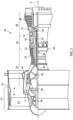
- FIG. 1 diagrammatically illustrates a gas turbine engine 20.
- the gas turbine engine 20 is disclosed herein as a two-spool turbofan that generally incorporates a fan section 22, a compressor section 24, a combustor section 26 and a turbine section 28.
- Alternative engines may include additional systems or features and may not include a gear reduction in the fan.
- the fan section 22 drives air along a bypass flow path B in a bypass duct defined within a nacelle 15, while the compressor section 24 drives air along a core flow path C for compression and communication into the combustor section 26 then expansion through the turbine section 28.
- the exemplary engine 20 generally includes a low speed spool 30 and a high speed spool 32 mounted for rotation about an engine central longitudinal axis X relative to an engine static structure 36 via several bearing systems 38. It should be understood that various bearing systems 38 at various locations may alternatively or additionally be provided, and the location of bearing systems 38 may be varied as appropriate to the application.
- the low speed spool 30 generally includes an inner shaft 40 that interconnects a fan 42, a low pressure compressor (LPC) 44 and a low pressure turbine (LPT) 46.
- the inner shaft 40 is connected to the fan 42 through a speed change mechanism, which in exemplary gas turbine engine 20 is illustrated as a geared architecture 48 to drive the fan 42 at a lower speed than the low speed spool 30.
- the high speed spool 32 includes an outer shaft 50 that interconnects a high pressure compressor (HPC) 52 and a high pressure turbine (HPT) 54.
- a combustor 56 is arranged in exemplary gas turbine 20 between the HPC 52 and the HPT 54.
- a mid-turbine frame 57 of the engine static structure 36 is arranged generally between the HPT 54 and the LPT 46. The mid-turbine frame 57 further supports bearing systems 38 in the turbine section 28.
- the inner shaft 40 and the outer shaft 50 are concentric and rotate via bearing systems 38 about the engine central longitudinal axis X which is collinear with their
- the core airflow is compressed by the LPC 44 then the HPC 52, mixed and burned with fuel in the combustor 56, then expanded over the HPT 54 and LPT 46.
- the mid-turbine frame 57 includes airfoils which are in the core airflow path C.
- the turbines 46, 54 rotationally drive the respective low speed spool 30 and high speed spool 32 in response to the expansion.
- gear system 48 may be located aft of combustor section 26 or even aft of turbine section 28, and fan section 22 may be positioned forward or aft of the location of gear system 48.
- the engine 20 may be a high-bypass geared aircraft engine.
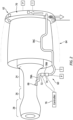
- An example anti-icing system 60 is diagrammatically illustrated in FIG. 2 in a nacelle inlet 62 application. Although the anti-icing system 60 is described herein in a gas turbine engine fan nacelle 64 application, the system 60 may be used alternatively to de-ice other aircraft structures, such as an aircraft wing.
- the system 60 includes at least one bleed source supply 66, a circumferentially extending duct disposed at the nacelle inlet 62 (e.g., a "D-duct 70"), a pressure regulating and shut off valve (“PRSOV 72"), at least one pressure relief valve (“PRV 74”), and a controller 76 in communication with one or more of these components.
- a circumferentially extending duct disposed at the nacelle inlet 62 e.g., a "D-duct 70"
- PRSOV 72 pressure regulating and shut off valve
- PRV 74 pressure relief valve
- the system 60 further includes a plurality of duct segments 78A-C fluidly connecting the system components.
- the system 60 may include one or more pressure sensors (P), temperature sensors (T), flow restrictors, bleed valves, check valves, and any combination thereof.
- the bleed source supply 66 is configured to provide bleed gas at an elevated pressure and temperature from a compressor section 24 stage (e.g., a stage within the HPC 52), or from a turbine section 28 stage (e.g., a stage within the LPT 44), or any combination thereof for use within the anti-icing system 60.
- air bled from a compressor stage will consist of ambient air drawn into the gas turbine engine and worked to an elevated pressure and temperature within one or more compressor stages.
- Air bled from a turbine stage (downstream of the combustor section 26) will include ambient air worked within the compressor section 24 as well as combustion products produced by combustion within the combustor section.
- the term "bleed air” or "bled air” may not be strictly limited to ambient air.
- the present disclosure system 60 is described herein in terms of an engine nacelle anti-icing configuration that includes a circumferentially extending duct 70 disposed at the inlet 62 of a nacelle 64.
- the inlet 62 of a nacelle 64 is defined by one or more panels that define an air passage into the gas turbine engine.
- the terms "forward”, “leading”, “aft, “trailing” are used herein to indicate the relative position of a component or surface relative to core gas flow or ambient air during flight. Core gas flow passing through the engine will encounter a "forward" end or “leading” edge of a component before it encounters an "aft" end or “trailing" edge of the component.
- the inlet 62 of a nacelle 64 is disposed at a forward or leading edge and therefore encounters ambient air before the remainder of the nacelle 64.
- the circumferentially extending duct 70 is configured as the leading edge of the nacelle 64 and may at least in part define the inlet 62 of the nacelle 64.
- the circumferentially extending duct 70 may have a "D" shaped configuration.
- the nacelle 64 leading edge duct will be referred to herein as a "D-duct 70".
- the present disclosure is not however limited to any particular nacelle leading edge duct geometry, and the leading edge duct geometry may extend around all or less then all of the nacelle inlet 62 circumference.
- the D-duct 70 has an interior cavity 80 configured to contain bleed air internally around at least a portion of the nacelle inlet 62 circumference.
- the present disclosure system 60 may include a distribution system 82 within the D-duct 70 that is intended to either distribute the bleed air uniformly within the D-duct 70 or distribute bleed air to targeted regions within the D-duct 70 (e.g., areas where ice accretion occurs on an exterior surface of the D-duct 70).
- a distribution system 82 is a Piccolo tube 82A (e.g., see FIG. 4 ) that is disposed within the interior cavity 80 of the D-duct 70.
- the Piccolo tube 82A is in fluid communication with a source of bleed air and includes a plurality of vent apertures through which bleed air may pass out of the Piccolo tube 82A and into the interior cavity 80 of the D-duct 70.
- D-ducts 70 may include interior baffles that direct bleed air within the D-duct interior cavity (e.g., along a path that is proximate the inner surface of the D-duct 70, forward to aft within the interior cavity 80, and the like).
- the present disclosure does not require a D-duct 70 bleed air distribution system 82, and if one is included the present disclosure is not limited to any particular D-duct bleed air distribution system 82 configuration.
- the D-duct 70 may include exhaust ports 84 (e.g., see FIG. 3 ) that permit bleed air disposed within the D-duct 70 to escape to the exterior environment.
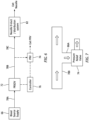
- a duct segment 78A provides fluid communication from the bleed source supply 66 (e.g., a compressor stage and/or a turbine stage) to the PRSOV 72.
- the PRSOV 72 is downstream of the bleed source supply 66.
- the PRSOV 72 is in communication with the controller 76 and may be selectively actuated to be in a number of different operating positions; e.g., in a fully open configuration (wherein bleed air at the maximum volumetric rate permissible for the PRSOV 72 passes through the PRSOV 72), a fully closed configuration (where no bleed air passes through the PRSOV 72), or a plurality of partially open/closed positions (where less than the maximum volumetric rate but more than zero passes through the PRSOV 72; e.g., 75%, 50%, 25%, and the like).
- the PRSOV 72 may be configured to provide position feedback (e.g., feedback regarding the position of a valve body portion of the PRSOV 72) to facilitate control of the PRSOV 72.
- Another duct segment 78B provides fluid communication from the PRSOV 72 to a PRV 74.
- the PRV 74 is downstream of the PRSOV 72.
- the PRV 74 is configured to selectively permit a flow of bleed gas to exit the anti-icing system 60.
- the PRV 74 may be disposed in any arrangement that permits bleed gas to exit the anti-icing system 60; e.g., the duct segment 78B is in fluid communication with the PRV 74 through a single port 86A tapped off the duct segment 78B (e.g., FIG.
- the duct segment 78B may be in fluid communication with the PRV 74 through a plurality of ports 86A, 86B tapped off the duct segment 78B (e.g., FIG. 8 ).
- the system may include more than one PRV 74 in fluid communication with the duct segment downstream of the PRSOV 72.
- Bleed gas exiting the anti-icing system 60 through the PRV 74 may be directed to other aircraft systems such as an aircraft cabin environmental system (e.g., for heating purposes), or it may be directed to a drain duct that passes the bleed air to the ambient environment, or the like, or any combination thereof.
- the PRV 74 is in communication with the controller 76 and may be actuated to be in a number of different operating positions; e.g., in a fully open configuration (wherein bleed air at the maximum volumetric rate permissible for the PRV 74 passes through the PRV 74), a fully closed configuration (where no bleed air passes through the PRV 74), or a plurality of partially open/closed positions (where less than the maximum volumetric rate of bleed air but more than zero passes through the PRV 74; e.g., 75%, 50%, 25%, and the like).
- the PRV 74 may be configured to provide position feedback (e.g., feedback regarding the position of a valve body portion of the PRV 74) to facilitate control of the PRV 74.
- the duct segment 78B in fluid communication with the PRV 74 is in communication with a duct segment 78C in fluid communication with the D-duct 70.
- the duct segment 78C is in fluid communication with the distribution system 82 to provide fluid passage of bleed air into the D-duct interior cavity 80.
- the controller 76 may include any type of computing device, computational circuit, processor(s), CPU, computer, or the like capable of executing a series of instructions that are stored in memory.
- the instructions may include an operating system, and/or executable software modules such as program files, system data, buffers, drivers, utilities, and the like.
- the executable instructions may apply to any functionality described herein to enable the system 60 to accomplish the same algorithmically and/or coordination of system components.
- the controller 76 includes or is in communication with one or more memory devices. The present disclosure is not limited to any particular type of memory device, and the memory device may store instructions and/or data in a non-transitory manner.
- Examples of memory devices that may be used include read-only memory, random access memory, volatile memory, non-volatile memory, static memory, dynamic memory, flash memory, cache memory, and/or any device that stores digital information. Communications between the controller 76 and other system components may be via a hardwire connection. A will be described herein, the controller 76 may be programmed (e.g., stored instructions) to regulate a flow of the bleed air, to the D-duct interior cavity 80 using PRSOV 72 and the PRV 74. The controller 76 may be configured with multiple channels to provide system robustness. In some embodiments, the controller 76 may be provided by a full authority digital engine control (FADEC) located within the engine.
- FADEC full authority digital engine control
- the present system 60 may include one or more pressure sensors (P) in communication with a duct segment 78A-C, or in communication with the D-duct interior cavity 80, or both.
- the pressure sensors are in signal communication with the controller 76.
- the present system 60 may include one or more temperature sensors (T) configured to sense the air temperature within a duct segment 78A-C or a component temperature related to the air temperature, produce signals representative thereof, and communicate those signals to the controller 76.
- One or more temperature sensors may be configured to sense the air temperature within the D-duct 80 (or a component), produce signals representative thereof, and communicate those signals to the controller 76.
- the controller 76 can use temperature sensor data, for example, to evaluate whether the nacelle inlet 62 is de-iced, or to evaluate system performance conditions; e.g., excessive bleed air volumetric flow, excessive bleed air temperature, and the like.
- the controller 76 can also use pressure sensor data, for example, to evaluate system performance conditions; e.g., excessive bleed air volumetric flow, and the like.
- MMEL Master Minimum Equipment List
- FAA Federal Aviation Administration
- EASA European Aviation Safety Agency
- MEL Minimum Equipment List
- the philosophy behind MMEL and related Minimum Equipment List (MEL) is to authorize release of flight with inoperative equipment only when the inoperative equipment does not render the aircraft unairworthy for the particular flight to avoid revenue loss to the operator and discomfort to the passengers.
- the MMEL may be associated with special operating conditions, limitations or procedures. In some instances, the MMEL may dictate operating conditions (e.g., maximum pressures, etc.) that a system aboard the aircraft must be able to withstand during operation.
- a failure of a PRSOV 72 in a fully open condition or a burst duct may lead to elevated bleed air pressure within the anti-icing system 60 or elsewhere within the nacelle 64.
- the MMEL may dictate that components within the nacelle 64 anti-icing system 60 must be able to withstand an elevated air pressure associated with a component failure; e.g., a failure of a PRSOV 72 or a burst duct.
- anti-icing system 60 components e.g., system ducts 78A-C, D-duct distribution components 82 such as a Piccolo tube and its attachment hardware, seals disposed between the D-duct 70 and the mating nacelle 64 components, and other nacelle 64 components
- D-duct distribution components 82 such as a Piccolo tube and its attachment hardware
- seals disposed between the D-duct 70 and the mating nacelle 64 components, and other nacelle 64 components have conventionally been designed to accommodate the elevated pressure.
- the controller 76 is programmed (e.g., stored instructions) to control the PRSOV 72 to an appropriate open/closed position and regulate the bleed air flow into the anti-icing system 60 to establish normal operating condition parameters when the anti-icing system 60 is required. If a bleed air parameter such as bleed air pressure is determined to be outside of normal operating conditions within the anti-icing system 60, the controller 76 may signal the PRSOV 72 (or other system component) to adjust in response thereto.
- the controller 76 may control the PRV 74 disposed downstream of the PRSOV 72 to bleed some portion of the bleed air away from the downstream anti-icing system 60 components; e.g., bleed a sufficient amount of bleed air away so that the bleed air pressure within the downstream portion of the anti-icing system 60 is at or close to normal operating conditions.
- bleed gas exiting the anti-icing system 60 through the PRV 74 may be directed to other aircraft systems such as an aircraft cabin environmental system, or a drain duct that passes the bleed air to the ambient environment, or the like, or any combination thereof.
- the PRV 74 is configured to satisfy the requirements of the particular anti-icing system 60 in which it is utilized, and the anti-icing system 60 is configured for the particular aircraft application.
- the PRV 74 may be configured (e.g., larger or smaller maximum volumetric flow rates) to satisfy the requirements of that particular aircraft application.
- the PRV 74 may be configured to bleed an amount of bleed air from the bleed air duct downstream of the PRSOV 72 to reduce the system bleed air pressure from a MMEL pressure constraint value to a bleed air pressure within normal operating conditions.
- the PRV 74 may be in communication with a single port 86A off of the duct segment 78B extending downstream from the PRSOV 72 (e.g., see FIG.
- the PRV 74 may be in communication with a plurality of ports 86A, 86B off of the duct segment 78B extending downstream from the PRSOV 72 (e.g., see FIG. 8 ), or the present system 60 may include more than one PRV 74.
- the collective volumetric flow capacity of the PRV(s) 74 is adequate to bleed a sufficient amount of bleed air away so that the bleed air pressure within the downstream portion of the anti-icing system 60 is at or close to normal operating conditions.
- the use of a PRV 74 downstream of the PRSOV 72 in the present disclosure anti-icing system 60 yields several benefits. For example, because excessive bleed air pressures are addressed by the PRV 74 it may no longer be necessary to configure the nacelle lip skin, forward bulkhead, aft bulkhead, bleed air ducts, D-duct distribution system hardware (e.g., Piccolo tube and associated hardware, or a swirl flow system, internal baffles, and the like), and associated seals to comply with the MMEL high-end bleed air pressure requirements. The understood concomitant weight savings and reduced cost are desirable.
- the present disclosure system also provides an attractive alternative to systems that utilize pulse modulation in response to an excessive bleed air pressure condition.
- Pulse modulation systems address excessive bleed air pressure condition by pulsing bleed air into the anti-icing system 60. Such systems may create unintended consequences like material fatigue within the anti-icing system 60 due to thermal stress.
- the present system also mitigates the potential for lip skin fastener compromise (e.g., failure or loosening) that may occur with excessive bleed air pressure.
- the present system 60 may also facilitate testing standards; e.g., it may be possible to satisfy system acceptance testing at lower normal operating pressure levels rather than at MMEL pressure levels.
- any one of these structures may describe the operations as a sequential process, many of the operations can be performed in parallel or concurrently.
- the order of the operations may be rearranged.
- a process may correspond to a method, a function, a procedure, a subroutine, a subprogram, etc.
Landscapes
- Engineering & Computer Science (AREA)
- Chemical & Material Sciences (AREA)
- Combustion & Propulsion (AREA)
- Mechanical Engineering (AREA)
- General Engineering & Computer Science (AREA)
- Structures Of Non-Positive Displacement Pumps (AREA)
- Aviation & Aerospace Engineering (AREA)
Applications Claiming Priority (1)
| Application Number | Priority Date | Filing Date | Title |
|---|---|---|---|
| IN202311006132 | 2023-01-31 |
Publications (1)
| Publication Number | Publication Date |
|---|---|
| EP4411123A1 true EP4411123A1 (de) | 2024-08-07 |
Family
ID=89771696
Family Applications (1)
| Application Number | Title | Priority Date | Filing Date |
|---|---|---|---|
| EP24155060.7A Pending EP4411123A1 (de) | 2023-01-31 | 2024-01-31 | Flugzeugvereisungsschutzsystem |
Country Status (2)
| Country | Link |
|---|---|
| US (1) | US20240254894A1 (de) |
| EP (1) | EP4411123A1 (de) |
Families Citing this family (1)
| Publication number | Priority date | Publication date | Assignee | Title |
|---|---|---|---|---|
| US12241410B1 (en) * | 2024-03-04 | 2025-03-04 | The Boeing Company | Engine nacelle anti-ice swirl system with unsteady fluid flow |
Citations (4)
| Publication number | Priority date | Publication date | Assignee | Title |
|---|---|---|---|---|
| GB2461385A (en) * | 2008-07-02 | 2010-01-06 | Boeing Co | Thermal anti-ice system for an aircraft engine |
| WO2015109098A1 (en) * | 2014-01-16 | 2015-07-23 | National Machine Company | Pressure regulating and distribution de-icing valve assembly for aircraft |
| EP3034813A1 (de) * | 2014-12-15 | 2016-06-22 | United Technologies Corporation | Flugzeugenteisungssystem |
| EP4102042A1 (de) * | 2021-06-07 | 2022-12-14 | Rohr, Inc. | Flugzeug-druckluftanlage mit zwei druckquellen und druckentlastung |
Family Cites Families (7)
| Publication number | Priority date | Publication date | Assignee | Title |
|---|---|---|---|---|
| US4688745A (en) * | 1986-01-24 | 1987-08-25 | Rohr Industries, Inc. | Swirl anti-ice system |
| FR2772341B1 (fr) * | 1997-12-12 | 2000-03-24 | Aerospatiale | Diffuseur d'air chaud pour capot d'entree d'air de moteur a reaction a circuit de degivrage |
| US6267328B1 (en) * | 1999-10-21 | 2001-07-31 | Rohr, Inc. | Hot air injection for swirling rotational anti-icing system |
| US6354538B1 (en) * | 1999-10-25 | 2002-03-12 | Rohr, Inc. | Passive control of hot air injection for swirling rotational type anti-icing system |
| FR3009278B1 (fr) * | 2013-07-30 | 2016-12-23 | Airbus Operations Sas | Procede de regulation du degivrage d'un bord d'attaque d'un aeronef et dispositif pour sa mise en oeuvre |
| US11167855B2 (en) * | 2019-04-30 | 2021-11-09 | Rohr, Inc. | Method and apparatus for aircraft anti-icing |
| US11465758B2 (en) * | 2019-04-30 | 2022-10-11 | Rohr, Inc. | Method and apparatus for aircraft anti-icing |
-
2024
- 2024-01-31 US US18/428,881 patent/US20240254894A1/en active Pending
- 2024-01-31 EP EP24155060.7A patent/EP4411123A1/de active Pending
Patent Citations (4)
| Publication number | Priority date | Publication date | Assignee | Title |
|---|---|---|---|---|
| GB2461385A (en) * | 2008-07-02 | 2010-01-06 | Boeing Co | Thermal anti-ice system for an aircraft engine |
| WO2015109098A1 (en) * | 2014-01-16 | 2015-07-23 | National Machine Company | Pressure regulating and distribution de-icing valve assembly for aircraft |
| EP3034813A1 (de) * | 2014-12-15 | 2016-06-22 | United Technologies Corporation | Flugzeugenteisungssystem |
| EP4102042A1 (de) * | 2021-06-07 | 2022-12-14 | Rohr, Inc. | Flugzeug-druckluftanlage mit zwei druckquellen und druckentlastung |
Also Published As
| Publication number | Publication date |
|---|---|
| US20240254894A1 (en) | 2024-08-01 |
Similar Documents
| Publication | Publication Date | Title |
|---|---|---|
| US12031484B2 (en) | Gas turbine engine cooling system control | |
| EP3106646B1 (de) | Gebläsetriebwerk mit einem kühlluftsystem sowie ein dazugehöriges verfahren | |
| US10421551B2 (en) | Aircraft anti-icing system | |
| EP2098704B1 (de) | Managementsystem des Fanflatterns in einem Turbofan mit variablem Fandüsenquerschnitt | |
| US9074531B2 (en) | Variable area fan nozzle fan flutter management system | |
| CA2768929C (en) | Environmental control system supply precooler bypass | |
| EP3354572B1 (de) | Flugzeugzapfsystem | |
| EP3406881B1 (de) | Steuerung eines verdichters eines gasturbinenmotors | |
| EP2904231B1 (de) | Gasturbinenmotor mit zapfluftsystem mit zapfluftentnahmestellen vor und nach dem verdichter sowie entsprechendes verfahren | |
| EP4411123A1 (de) | Flugzeugvereisungsschutzsystem | |
| EP4397845A1 (de) | Enteisungssystem und verfahren für ein flugzeugantriebssystem | |
| EP3546734B1 (de) | Gasturbine mit einer variablen austrittsdüse zur handhabung von gebläseflatterschwingungen | |
| US12180911B2 (en) | Ducted firewall with upper bifi bleed for modulated core ventilation | |
| US20240352892A1 (en) | Multi-valve modulated core ventilation | |
| US12553392B2 (en) | Gas turbine engine with thermal management | |
| US20260055774A1 (en) | Gas turbine engine bleed air flow control | |
| US20260062134A1 (en) | Assembly for identifying obstructing foreign matter in an air intake of an aircraft propulsion system and method of using same | |
| EP4438985A1 (de) | Wärmetauscheranordnung für ein flugzeug |
Legal Events
| Date | Code | Title | Description |
|---|---|---|---|
| PUAI | Public reference made under article 153(3) epc to a published international application that has entered the european phase |
Free format text: ORIGINAL CODE: 0009012 |
|
| STAA | Information on the status of an ep patent application or granted ep patent |
Free format text: STATUS: THE APPLICATION HAS BEEN PUBLISHED |
|
| AK | Designated contracting states |
Kind code of ref document: A1 Designated state(s): AL AT BE BG CH CY CZ DE DK EE ES FI FR GB GR HR HU IE IS IT LI LT LU LV MC ME MK MT NL NO PL PT RO RS SE SI SK SM TR |
|
| STAA | Information on the status of an ep patent application or granted ep patent |
Free format text: STATUS: REQUEST FOR EXAMINATION WAS MADE |
|
| 17P | Request for examination filed |
Effective date: 20250207 |