EP4411198A2 - Récipient haute pression - Google Patents
Récipient haute pression Download PDFInfo
- Publication number
- EP4411198A2 EP4411198A2 EP24183320.1A EP24183320A EP4411198A2 EP 4411198 A2 EP4411198 A2 EP 4411198A2 EP 24183320 A EP24183320 A EP 24183320A EP 4411198 A2 EP4411198 A2 EP 4411198A2
- Authority
- EP
- European Patent Office
- Prior art keywords
- shell
- foot part
- groove
- plastic
- insert
- Prior art date
- Legal status (The legal status is an assumption and is not a legal conclusion. Google has not performed a legal analysis and makes no representation as to the accuracy of the status listed.)
- Granted
Links
Images

Classifications
-
- F—MECHANICAL ENGINEERING; LIGHTING; HEATING; WEAPONS; BLASTING
- F17—STORING OR DISTRIBUTING GASES OR LIQUIDS
- F17C—VESSELS FOR CONTAINING OR STORING COMPRESSED, LIQUEFIED OR SOLIDIFIED GASES; FIXED-CAPACITY GAS-HOLDERS; FILLING VESSELS WITH, OR DISCHARGING FROM VESSELS, COMPRESSED, LIQUEFIED, OR SOLIDIFIED GASES
- F17C1/00—Pressure vessels, e.g. gas cylinder, gas tank, replaceable cartridge
- F17C1/02—Pressure vessels, e.g. gas cylinder, gas tank, replaceable cartridge involving reinforcing arrangements
- F17C1/04—Protecting sheathings
- F17C1/06—Protecting sheathings built-up from wound-on bands or filamentary material, e.g. wires
-
- F—MECHANICAL ENGINEERING; LIGHTING; HEATING; WEAPONS; BLASTING
- F17—STORING OR DISTRIBUTING GASES OR LIQUIDS
- F17C—VESSELS FOR CONTAINING OR STORING COMPRESSED, LIQUEFIED OR SOLIDIFIED GASES; FIXED-CAPACITY GAS-HOLDERS; FILLING VESSELS WITH, OR DISCHARGING FROM VESSELS, COMPRESSED, LIQUEFIED, OR SOLIDIFIED GASES
- F17C1/00—Pressure vessels, e.g. gas cylinder, gas tank, replaceable cartridge
- F17C1/16—Pressure vessels, e.g. gas cylinder, gas tank, replaceable cartridge constructed of plastics materials
-
- F—MECHANICAL ENGINEERING; LIGHTING; HEATING; WEAPONS; BLASTING
- F17—STORING OR DISTRIBUTING GASES OR LIQUIDS
- F17C—VESSELS FOR CONTAINING OR STORING COMPRESSED, LIQUEFIED OR SOLIDIFIED GASES; FIXED-CAPACITY GAS-HOLDERS; FILLING VESSELS WITH, OR DISCHARGING FROM VESSELS, COMPRESSED, LIQUEFIED, OR SOLIDIFIED GASES
- F17C13/00—Details of vessels or of the filling or discharging of vessels
-
- F—MECHANICAL ENGINEERING; LIGHTING; HEATING; WEAPONS; BLASTING
- F17—STORING OR DISTRIBUTING GASES OR LIQUIDS
- F17C—VESSELS FOR CONTAINING OR STORING COMPRESSED, LIQUEFIED OR SOLIDIFIED GASES; FIXED-CAPACITY GAS-HOLDERS; FILLING VESSELS WITH, OR DISCHARGING FROM VESSELS, COMPRESSED, LIQUEFIED, OR SOLIDIFIED GASES
- F17C2201/00—Vessel construction, in particular geometry, arrangement or size
- F17C2201/01—Shape
- F17C2201/0104—Shape cylindrical
-
- F—MECHANICAL ENGINEERING; LIGHTING; HEATING; WEAPONS; BLASTING
- F17—STORING OR DISTRIBUTING GASES OR LIQUIDS
- F17C—VESSELS FOR CONTAINING OR STORING COMPRESSED, LIQUEFIED OR SOLIDIFIED GASES; FIXED-CAPACITY GAS-HOLDERS; FILLING VESSELS WITH, OR DISCHARGING FROM VESSELS, COMPRESSED, LIQUEFIED, OR SOLIDIFIED GASES
- F17C2201/00—Vessel construction, in particular geometry, arrangement or size
- F17C2201/01—Shape
- F17C2201/0104—Shape cylindrical
- F17C2201/0109—Shape cylindrical with exteriorly curved end-piece
-
- F—MECHANICAL ENGINEERING; LIGHTING; HEATING; WEAPONS; BLASTING
- F17—STORING OR DISTRIBUTING GASES OR LIQUIDS
- F17C—VESSELS FOR CONTAINING OR STORING COMPRESSED, LIQUEFIED OR SOLIDIFIED GASES; FIXED-CAPACITY GAS-HOLDERS; FILLING VESSELS WITH, OR DISCHARGING FROM VESSELS, COMPRESSED, LIQUEFIED, OR SOLIDIFIED GASES
- F17C2201/00—Vessel construction, in particular geometry, arrangement or size
- F17C2201/01—Shape
- F17C2201/0128—Shape spherical or elliptical
-
- F—MECHANICAL ENGINEERING; LIGHTING; HEATING; WEAPONS; BLASTING
- F17—STORING OR DISTRIBUTING GASES OR LIQUIDS
- F17C—VESSELS FOR CONTAINING OR STORING COMPRESSED, LIQUEFIED OR SOLIDIFIED GASES; FIXED-CAPACITY GAS-HOLDERS; FILLING VESSELS WITH, OR DISCHARGING FROM VESSELS, COMPRESSED, LIQUEFIED, OR SOLIDIFIED GASES
- F17C2201/00—Vessel construction, in particular geometry, arrangement or size
- F17C2201/05—Size
- F17C2201/056—Small (<1 m3)
-
- F—MECHANICAL ENGINEERING; LIGHTING; HEATING; WEAPONS; BLASTING
- F17—STORING OR DISTRIBUTING GASES OR LIQUIDS
- F17C—VESSELS FOR CONTAINING OR STORING COMPRESSED, LIQUEFIED OR SOLIDIFIED GASES; FIXED-CAPACITY GAS-HOLDERS; FILLING VESSELS WITH, OR DISCHARGING FROM VESSELS, COMPRESSED, LIQUEFIED, OR SOLIDIFIED GASES
- F17C2203/00—Vessel construction, in particular walls or details thereof
- F17C2203/06—Materials for walls or layers thereof; Properties or structures of walls or their materials
- F17C2203/0602—Wall structures; Special features thereof
- F17C2203/0604—Liners
-
- F—MECHANICAL ENGINEERING; LIGHTING; HEATING; WEAPONS; BLASTING
- F17—STORING OR DISTRIBUTING GASES OR LIQUIDS
- F17C—VESSELS FOR CONTAINING OR STORING COMPRESSED, LIQUEFIED OR SOLIDIFIED GASES; FIXED-CAPACITY GAS-HOLDERS; FILLING VESSELS WITH, OR DISCHARGING FROM VESSELS, COMPRESSED, LIQUEFIED, OR SOLIDIFIED GASES
- F17C2203/00—Vessel construction, in particular walls or details thereof
- F17C2203/06—Materials for walls or layers thereof; Properties or structures of walls or their materials
- F17C2203/0602—Wall structures; Special features thereof
- F17C2203/0612—Wall structures
- F17C2203/0614—Single wall
- F17C2203/0621—Single wall with three layers
-
- F—MECHANICAL ENGINEERING; LIGHTING; HEATING; WEAPONS; BLASTING
- F17—STORING OR DISTRIBUTING GASES OR LIQUIDS
- F17C—VESSELS FOR CONTAINING OR STORING COMPRESSED, LIQUEFIED OR SOLIDIFIED GASES; FIXED-CAPACITY GAS-HOLDERS; FILLING VESSELS WITH, OR DISCHARGING FROM VESSELS, COMPRESSED, LIQUEFIED, OR SOLIDIFIED GASES
- F17C2203/00—Vessel construction, in particular walls or details thereof
- F17C2203/06—Materials for walls or layers thereof; Properties or structures of walls or their materials
- F17C2203/0602—Wall structures; Special features thereof
- F17C2203/0612—Wall structures
- F17C2203/0626—Multiple walls
-
- F—MECHANICAL ENGINEERING; LIGHTING; HEATING; WEAPONS; BLASTING
- F17—STORING OR DISTRIBUTING GASES OR LIQUIDS
- F17C—VESSELS FOR CONTAINING OR STORING COMPRESSED, LIQUEFIED OR SOLIDIFIED GASES; FIXED-CAPACITY GAS-HOLDERS; FILLING VESSELS WITH, OR DISCHARGING FROM VESSELS, COMPRESSED, LIQUEFIED, OR SOLIDIFIED GASES
- F17C2203/00—Vessel construction, in particular walls or details thereof
- F17C2203/06—Materials for walls or layers thereof; Properties or structures of walls or their materials
- F17C2203/0634—Materials for walls or layers thereof
- F17C2203/0658—Synthetics
- F17C2203/066—Plastics
-
- F—MECHANICAL ENGINEERING; LIGHTING; HEATING; WEAPONS; BLASTING
- F17—STORING OR DISTRIBUTING GASES OR LIQUIDS
- F17C—VESSELS FOR CONTAINING OR STORING COMPRESSED, LIQUEFIED OR SOLIDIFIED GASES; FIXED-CAPACITY GAS-HOLDERS; FILLING VESSELS WITH, OR DISCHARGING FROM VESSELS, COMPRESSED, LIQUEFIED, OR SOLIDIFIED GASES
- F17C2203/00—Vessel construction, in particular walls or details thereof
- F17C2203/06—Materials for walls or layers thereof; Properties or structures of walls or their materials
- F17C2203/0634—Materials for walls or layers thereof
- F17C2203/0658—Synthetics
- F17C2203/0663—Synthetics in form of fibers or filaments
-
- F—MECHANICAL ENGINEERING; LIGHTING; HEATING; WEAPONS; BLASTING
- F17—STORING OR DISTRIBUTING GASES OR LIQUIDS
- F17C—VESSELS FOR CONTAINING OR STORING COMPRESSED, LIQUEFIED OR SOLIDIFIED GASES; FIXED-CAPACITY GAS-HOLDERS; FILLING VESSELS WITH, OR DISCHARGING FROM VESSELS, COMPRESSED, LIQUEFIED, OR SOLIDIFIED GASES
- F17C2203/00—Vessel construction, in particular walls or details thereof
- F17C2203/06—Materials for walls or layers thereof; Properties or structures of walls or their materials
- F17C2203/0634—Materials for walls or layers thereof
- F17C2203/0658—Synthetics
- F17C2203/0663—Synthetics in form of fibers or filaments
- F17C2203/0673—Polymers
-
- F—MECHANICAL ENGINEERING; LIGHTING; HEATING; WEAPONS; BLASTING
- F17—STORING OR DISTRIBUTING GASES OR LIQUIDS
- F17C—VESSELS FOR CONTAINING OR STORING COMPRESSED, LIQUEFIED OR SOLIDIFIED GASES; FIXED-CAPACITY GAS-HOLDERS; FILLING VESSELS WITH, OR DISCHARGING FROM VESSELS, COMPRESSED, LIQUEFIED, OR SOLIDIFIED GASES
- F17C2203/00—Vessel construction, in particular walls or details thereof
- F17C2203/06—Materials for walls or layers thereof; Properties or structures of walls or their materials
- F17C2203/0634—Materials for walls or layers thereof
- F17C2203/0658—Synthetics
- F17C2203/0675—Synthetics with details of composition
-
- F—MECHANICAL ENGINEERING; LIGHTING; HEATING; WEAPONS; BLASTING
- F17—STORING OR DISTRIBUTING GASES OR LIQUIDS
- F17C—VESSELS FOR CONTAINING OR STORING COMPRESSED, LIQUEFIED OR SOLIDIFIED GASES; FIXED-CAPACITY GAS-HOLDERS; FILLING VESSELS WITH, OR DISCHARGING FROM VESSELS, COMPRESSED, LIQUEFIED, OR SOLIDIFIED GASES
- F17C2205/00—Vessel construction, in particular mounting arrangements, attachments or identifications means
- F17C2205/03—Fluid connections, filters, valves, closure means or other attachments
- F17C2205/0302—Fittings, valves, filters, or components in connection with the gas storage device
-
- F—MECHANICAL ENGINEERING; LIGHTING; HEATING; WEAPONS; BLASTING
- F17—STORING OR DISTRIBUTING GASES OR LIQUIDS
- F17C—VESSELS FOR CONTAINING OR STORING COMPRESSED, LIQUEFIED OR SOLIDIFIED GASES; FIXED-CAPACITY GAS-HOLDERS; FILLING VESSELS WITH, OR DISCHARGING FROM VESSELS, COMPRESSED, LIQUEFIED, OR SOLIDIFIED GASES
- F17C2205/00—Vessel construction, in particular mounting arrangements, attachments or identifications means
- F17C2205/03—Fluid connections, filters, valves, closure means or other attachments
- F17C2205/0302—Fittings, valves, filters, or components in connection with the gas storage device
- F17C2205/0305—Bosses, e.g. boss collars
-
- F—MECHANICAL ENGINEERING; LIGHTING; HEATING; WEAPONS; BLASTING
- F17—STORING OR DISTRIBUTING GASES OR LIQUIDS
- F17C—VESSELS FOR CONTAINING OR STORING COMPRESSED, LIQUEFIED OR SOLIDIFIED GASES; FIXED-CAPACITY GAS-HOLDERS; FILLING VESSELS WITH, OR DISCHARGING FROM VESSELS, COMPRESSED, LIQUEFIED, OR SOLIDIFIED GASES
- F17C2205/00—Vessel construction, in particular mounting arrangements, attachments or identifications means
- F17C2205/03—Fluid connections, filters, valves, closure means or other attachments
- F17C2205/0388—Arrangement of valves, regulators, filters
- F17C2205/0394—Arrangement of valves, regulators, filters in direct contact with the pressure vessel
- F17C2205/0397—Arrangement of valves, regulators, filters in direct contact with the pressure vessel on both sides of the pressure vessel
-
- F—MECHANICAL ENGINEERING; LIGHTING; HEATING; WEAPONS; BLASTING
- F17—STORING OR DISTRIBUTING GASES OR LIQUIDS
- F17C—VESSELS FOR CONTAINING OR STORING COMPRESSED, LIQUEFIED OR SOLIDIFIED GASES; FIXED-CAPACITY GAS-HOLDERS; FILLING VESSELS WITH, OR DISCHARGING FROM VESSELS, COMPRESSED, LIQUEFIED, OR SOLIDIFIED GASES
- F17C2209/00—Vessel construction, in particular methods of manufacturing
- F17C2209/21—Shaping processes
- F17C2209/2109—Moulding
- F17C2209/2127—Moulding by blowing
-
- F—MECHANICAL ENGINEERING; LIGHTING; HEATING; WEAPONS; BLASTING
- F17—STORING OR DISTRIBUTING GASES OR LIQUIDS
- F17C—VESSELS FOR CONTAINING OR STORING COMPRESSED, LIQUEFIED OR SOLIDIFIED GASES; FIXED-CAPACITY GAS-HOLDERS; FILLING VESSELS WITH, OR DISCHARGING FROM VESSELS, COMPRESSED, LIQUEFIED, OR SOLIDIFIED GASES
- F17C2209/00—Vessel construction, in particular methods of manufacturing
- F17C2209/21—Shaping processes
- F17C2209/2154—Winding
-
- F—MECHANICAL ENGINEERING; LIGHTING; HEATING; WEAPONS; BLASTING
- F17—STORING OR DISTRIBUTING GASES OR LIQUIDS
- F17C—VESSELS FOR CONTAINING OR STORING COMPRESSED, LIQUEFIED OR SOLIDIFIED GASES; FIXED-CAPACITY GAS-HOLDERS; FILLING VESSELS WITH, OR DISCHARGING FROM VESSELS, COMPRESSED, LIQUEFIED, OR SOLIDIFIED GASES
- F17C2209/00—Vessel construction, in particular methods of manufacturing
- F17C2209/21—Shaping processes
- F17C2209/219—Working processes for non metal materials, e.g. extruding
-
- F—MECHANICAL ENGINEERING; LIGHTING; HEATING; WEAPONS; BLASTING
- F17—STORING OR DISTRIBUTING GASES OR LIQUIDS
- F17C—VESSELS FOR CONTAINING OR STORING COMPRESSED, LIQUEFIED OR SOLIDIFIED GASES; FIXED-CAPACITY GAS-HOLDERS; FILLING VESSELS WITH, OR DISCHARGING FROM VESSELS, COMPRESSED, LIQUEFIED, OR SOLIDIFIED GASES
- F17C2209/00—Vessel construction, in particular methods of manufacturing
- F17C2209/23—Manufacturing of particular parts or at special locations
- F17C2209/234—Manufacturing of particular parts or at special locations of closing end pieces, e.g. caps
-
- F—MECHANICAL ENGINEERING; LIGHTING; HEATING; WEAPONS; BLASTING
- F17—STORING OR DISTRIBUTING GASES OR LIQUIDS
- F17C—VESSELS FOR CONTAINING OR STORING COMPRESSED, LIQUEFIED OR SOLIDIFIED GASES; FIXED-CAPACITY GAS-HOLDERS; FILLING VESSELS WITH, OR DISCHARGING FROM VESSELS, COMPRESSED, LIQUEFIED, OR SOLIDIFIED GASES
- F17C2221/00—Handled fluid, in particular type of fluid
- F17C2221/01—Pure fluids
- F17C2221/012—Hydrogen
-
- F—MECHANICAL ENGINEERING; LIGHTING; HEATING; WEAPONS; BLASTING
- F17—STORING OR DISTRIBUTING GASES OR LIQUIDS
- F17C—VESSELS FOR CONTAINING OR STORING COMPRESSED, LIQUEFIED OR SOLIDIFIED GASES; FIXED-CAPACITY GAS-HOLDERS; FILLING VESSELS WITH, OR DISCHARGING FROM VESSELS, COMPRESSED, LIQUEFIED, OR SOLIDIFIED GASES
- F17C2223/00—Handled fluid before transfer, i.e. state of fluid when stored in the vessel or before transfer from the vessel
- F17C2223/01—Handled fluid before transfer, i.e. state of fluid when stored in the vessel or before transfer from the vessel characterised by the phase
- F17C2223/0107—Single phase
- F17C2223/0123—Single phase gaseous, e.g. CNG, GNC
-
- F—MECHANICAL ENGINEERING; LIGHTING; HEATING; WEAPONS; BLASTING
- F17—STORING OR DISTRIBUTING GASES OR LIQUIDS
- F17C—VESSELS FOR CONTAINING OR STORING COMPRESSED, LIQUEFIED OR SOLIDIFIED GASES; FIXED-CAPACITY GAS-HOLDERS; FILLING VESSELS WITH, OR DISCHARGING FROM VESSELS, COMPRESSED, LIQUEFIED, OR SOLIDIFIED GASES
- F17C2223/00—Handled fluid before transfer, i.e. state of fluid when stored in the vessel or before transfer from the vessel
- F17C2223/03—Handled fluid before transfer, i.e. state of fluid when stored in the vessel or before transfer from the vessel characterised by the pressure level
- F17C2223/036—Very high pressure (>80 bar)
-
- F—MECHANICAL ENGINEERING; LIGHTING; HEATING; WEAPONS; BLASTING
- F17—STORING OR DISTRIBUTING GASES OR LIQUIDS
- F17C—VESSELS FOR CONTAINING OR STORING COMPRESSED, LIQUEFIED OR SOLIDIFIED GASES; FIXED-CAPACITY GAS-HOLDERS; FILLING VESSELS WITH, OR DISCHARGING FROM VESSELS, COMPRESSED, LIQUEFIED, OR SOLIDIFIED GASES
- F17C2260/00—Purposes of gas storage and gas handling
- F17C2260/01—Improving mechanical properties or manufacturing
- F17C2260/013—Reducing manufacturing time or effort
-
- F—MECHANICAL ENGINEERING; LIGHTING; HEATING; WEAPONS; BLASTING
- F17—STORING OR DISTRIBUTING GASES OR LIQUIDS
- F17C—VESSELS FOR CONTAINING OR STORING COMPRESSED, LIQUEFIED OR SOLIDIFIED GASES; FIXED-CAPACITY GAS-HOLDERS; FILLING VESSELS WITH, OR DISCHARGING FROM VESSELS, COMPRESSED, LIQUEFIED, OR SOLIDIFIED GASES
- F17C2270/00—Applications
- F17C2270/01—Applications for fluid transport or storage
- F17C2270/0165—Applications for fluid transport or storage on the road
- F17C2270/0168—Applications for fluid transport or storage on the road by vehicles
-
- F—MECHANICAL ENGINEERING; LIGHTING; HEATING; WEAPONS; BLASTING
- F17—STORING OR DISTRIBUTING GASES OR LIQUIDS
- F17C—VESSELS FOR CONTAINING OR STORING COMPRESSED, LIQUEFIED OR SOLIDIFIED GASES; FIXED-CAPACITY GAS-HOLDERS; FILLING VESSELS WITH, OR DISCHARGING FROM VESSELS, COMPRESSED, LIQUEFIED, OR SOLIDIFIED GASES
- F17C2270/00—Applications
- F17C2270/01—Applications for fluid transport or storage
- F17C2270/0165—Applications for fluid transport or storage on the road
- F17C2270/0184—Fuel cells
-
- Y—GENERAL TAGGING OF NEW TECHNOLOGICAL DEVELOPMENTS; GENERAL TAGGING OF CROSS-SECTIONAL TECHNOLOGIES SPANNING OVER SEVERAL SECTIONS OF THE IPC; TECHNICAL SUBJECTS COVERED BY FORMER USPC CROSS-REFERENCE ART COLLECTIONS [XRACs] AND DIGESTS
- Y02—TECHNOLOGIES OR APPLICATIONS FOR MITIGATION OR ADAPTATION AGAINST CLIMATE CHANGE
- Y02E—REDUCTION OF GREENHOUSE GAS [GHG] EMISSIONS, RELATED TO ENERGY GENERATION, TRANSMISSION OR DISTRIBUTION
- Y02E60/00—Enabling technologies; Technologies with a potential or indirect contribution to GHG emissions mitigation
- Y02E60/30—Hydrogen technology
- Y02E60/32—Hydrogen storage
Definitions
- the present invention relates to a high-pressure container, in particular for storing a fuel for a motor vehicle.
- high-pressure containers for example for storing hydrogen as fuel for motor vehicles, can be constructed from an inner layer, the so-called “liner”, and a winding of fiber material around the liner.
- blow molding and thermoforming technologies to produce a container. Production is then based on the forming of tubular or plate-shaped semi-finished products. These are brought into their final shape by negative pressure and/or positive pressure. For example, two half-shells can be produced that are joined together to form a container.
- the materials used are mostly based on HDPE (high density polyethylene) or polyamides.
- Liner materials An important distinguishing feature for liner materials is the mechanical low-temperature properties and the emission properties.
- Monolayer materials such as polyamide have good barrier properties for gases, but do not have optimal low-temperature properties.
- HDPE on the other hand, does not have a suitable barrier effect, but does have very good low-temperature properties.
- polyamide is currently mainly used for applications in the hydrogen sector.
- the suitable types available are also expensive due to the complex additives they require and are problematic when used at low temperatures.
- High-pressure vessels for gases are subject to large temperature fluctuations during operation (filling, storing and emptying). This places high demands on the materials and in particular on the liner.
- a pressure vessel comprising a polymeric impermeable lining and a reinforcing layer of a composite material which is arranged outside the impermeable lining at least one projection connected to the impermeable liner and the reinforcing layer to provide an opening of the pressure vessel, the impermeable liner being connected to the projection by a co-molded annular polymer-metal bonding zone.
- the JP-H10-332085-A and the JP-H10-332083-A each disclose a pressure-resistant container having a gas-impermeable inner shell, a pressure-resistant outer shell covering the inner shell, and a mouthpiece attached to at least one pole of the container comprising both shells, the pole shoulder of the inner shell having a cylindrical neck projecting outwardly along the central axis of the inner shell; and the end of the projecting cylindrical neck being extended outwardly at right angles to the cylindrical neck to form an extension portion, the end of the extension portion being bent toward the shoulder of the inner shell to enclose the inner lower end of the mouthpiece.
- a pressure vessel comprising a main body having a reinforcing portion having a tubular configuration and a lining portion made of resin and covering an inner peripheral surface of the reinforcing portion; an orifice ring formed integrally with the main body to communicate an inside and an outside of the main body with each other; and a valve inserted into the orifice ring on an inner peripheral side thereof, the orifice ring having a cylindrical boss portion and a flange portion protruding outward from an outer peripheral surface of the boss portion; and the lining portion formed integrally with the orifice ring and a flange sealing portion covering a bottom surface of the flange part, and includes a hub seal part formed continuously with the flange seal part to cover at least a part of an inner peripheral surface of the hub part in the axial direction thereof, the hub seal part including a hub-side collar part protruding outward, and a sealing member consisting of an elastic body is arranged in a space between an inner
- the high-pressure vessel comprises a cylinder as a central part, wherein the cylinder consists of a multi-layer composite plastic which comprises a barrier layer, wherein the high-pressure vessel further comprises at least one half-shell at an axial end of the cylinder, wherein the half-shell consists of a multi-layer composite plastic which comprises a barrier layer, wherein the half-shell further comprises a substantially rotationally symmetrical insert part, namely a boss part, wherein the insert part has a foot part at the end of the insert part facing the interior of the container, which foot part has a larger diameter than a central part of the insert part, wherein the foot part essentially has a Forms a hollow cone or hollow cylinder and at least one first groove or depression filled with the multilayer composite plastic of the half-shell runs around a vertical inner circumference of the foot part, at least in sections.
- a multilayer composite is used as the material for the liner, both in the middle part formed by the cylinder and in at least one, preferably both, axial end regions of the container.
- Such multilayer plastics can be easily formed into a half-shell by means of blow molding or deep drawing or vacuum forming.
- the cylinder in the middle part can also be blow molded or extruded, for example.
- a boss part is used which has a foot part with a larger diameter than an adjacent middle part of the boss part.
- the foot part thus forms an undercut in relation to a multi-layer plastic liner introduced from the side of the foot part or the center of the container.
- the base part is hollow on the inside, in the area of its longitudinal central axis, and therefore essentially forms a hollow cone or a hollow cylinder.
- a first groove or depression runs at least in sections, for example in individual sectors, around the inner circumference, preferably also around the entire inner circumference of the hollow cylinder or hollow cone.
- This groove or depression is filled with the multi-layer composite plastic of the half-shell.
- a "depression" can be designed similarly to a groove, and in any case has at least one edge that acts as an undercut for the plastic behind it, so that the multi-layer plastic is held in a form-fitting manner behind the edge in the area of the inner circumference.
- the multi-layer plastic of the liner which has a barrier layer, increases the tightness in the area of the transition between the plastic liner and the boss part.
- the plastic in the first groove or recess arranged on the vertical inner circumference is well protected against detachment during operation of the high-pressure vessel, so that the good sealing properties of the vessel are particularly durable.
- the high-pressure vessel therefore has good permeation properties even in the area of the transition to the boss part.
- the production of the half-shell with embedded boss part and the entire high-pressure vessel is nevertheless possible in a cost-effective manner because, as will be described in more detail later, the plastic can be introduced by blow molding or vacuum deep drawing despite the undercut at the base of the boss part.
- the foot part has at least one second groove which is filled with the multi-layer composite plastic of the half-shell, the second groove running at least partially around the base of the foot part near the inner circumference of the foot part, facing the inside of the container.
- This groove also primarily serves to increase the tightness between the liner and the boss part.
- the foot part has at least one fourth groove which is filled with the multi-layer composite plastic of the half-shell, wherein the fourth groove is formed near the outer circumference of the foot part at the bottom of the foot part facing the interior of the container, at least in sections This groove also prevents the plastic from detaching from the boss part.
- the multi-layer composite plastic of the half shell is preferably arranged axially on both sides of the foot part.
- the boss part which is usually made of metal, is thus embedded in the plastic with the barrier layer.
- the base part has at least one third groove which is filled with the multi-layer composite plastic of the half-shell, the third groove running at least partially around the cover surface of the base part facing the outside of the container.
- this third groove also prevents the plastic from detaching from the boss part on the cover surface of the base part.
- the first groove and/or the second groove and/or the third groove and/or the fourth groove may have a trapezoidal shape which increases towards the bottom of the groove so that the form fit of the plastic in the groove is improved.
- an additional sealing element can be arranged at the bottom of the groove.
- a sleeve is arranged radially inside the first groove, inside the inner circumference of the foot part, whereby the multi-layer composite plastic of the half shell is pressed by the sleeve against the inner circumference of the foot part and into the first groove.
- the plastic thus remains reliably in the first groove and the sealing effect is further increased.
- the multilayer composite plastic of the cylinder preferably merges into the multilayer composite plastic of the half-shell.
- the barrier layer preferably runs as continuously as possible at the transition between the cylinder and the half-shell.
- the multilayer composite plastic of the half-shell, and preferably also the multilayer composite plastic of the cylinder, preferably comprises at least one layer of HDPE and a barrier layer, in particular EVOH, preferably also a regranulate, i.e. a regrind layer, and/or a second HDPE layer and/or at least one adhesion promoter layer.
- a barrier layer in particular EVOH, preferably also a regranulate, i.e. a regrind layer, and/or a second HDPE layer and/or at least one adhesion promoter layer.
- the high-pressure vessel comprises two half-shells at the axial ends of the cylinder, wherein preferably both half-shells are designed as previously described for the first half-shell.
- the cylinder and the two half-shells are preferably wrapped with a fiber material, preferably with a composite material comprising carbon fibers and/or glass fibers and/or epoxy resin.
- the boss part is inserted into the tool as an insert and enclosed in a blow molding or deep-drawing process with the plastic plate, in particular a permeation-tight multi-layer composite, so that the plastic also reaches areas behind an undercut.
- a plastic plate is first sucked or pressed onto the first half of the tool using negative pressure or pressure.
- the insert can already be positioned in such a way that by sucking or pressing the plastic onto the first half of the tool, the plastic of the first plastic plate is arranged in some areas behind an undercut of the insert, laterally spaced from the insert.
- the insert part can only be positioned after the plastic has been sucked or pressed onto the first tool half in such a way that the plastic of the first plastic plate is arranged behind the undercut at a laterally distance from the insert part, for example by moving the insert part or by only now inserting the insert part into the first tool half.
- the plastic of the first plastic plate is pressed or sucked from the side of the insert towards the insert, so that a space behind the undercut of the insert is filled with the plastic previously located on the side and a positive connection is created.
- “Laterally spaced” means essentially spaced from a longitudinal center axis of the insert, which can preferably also coincide with the longitudinal center axis of the pressure vessel.
- the plastic can initially run essentially parallel to the longitudinal center axis of the insert and preferably also to the surrounding vessel wall. The plastic is then sucked, blown or pushed essentially normal to the longitudinal center axis of the insert, in particular radially inwards on all sides, towards the insert.
- the fact that the plastic is sucked or pressed onto the insert part after the positioning of the insert part, so that the plastic is arranged laterally spaced from the insert part in some areas, can also take place in a continuous process, so that the insert part is moved and positioned further and new plastic is sucked or pressed in each time, so that the positioning of the insert part and the sucking or pressed of the plastic behind the undercut take place virtually simultaneously.
- the resulting half-shell can be connected to a second half-shell or an extruded or blow-molded multi-layer cylinder in a further process step.
- This forms the core and thus the basis for a further winding process in which the container can obtain its mechanical strength through a composite material made of carbon and/or glass and epoxy resin.
- the tool preferably comprises a second tool half that forms a stamp, the second tool half being moved onto the first tool half to form the inner contour of the half-shell.
- the second tool half can form the shape of the first plastic plate inside the half-shell.
- the second tool half can also be equipped with a second plastic plate that forms the inner contour of the half-shell.
- the insert is raised in relation to the first tool half in order to position the insert so that the plastic of the first plastic plate is arranged behind the undercut at a laterally spaced distance from the insert.
- the lifting can be carried out using a movable holder for the insert.
- the insert can be arranged on the outside of the container on the first plastic plate and the lifting can thus take place along the longitudinal center axis of the insert and preferably also along the longitudinal center axis of the high-pressure container, in particular in the direction of the later center of the container.
- the insert is lowered again after filling the space behind the undercut of the insert with the plastic, in relation to the first tool half. It is particularly preferred that the lowering takes place simultaneously with the movement of the second tool half onto the first tool half.
- the insert is only placed on the first plastic plate after the first plastic plate has been sucked or pressed onto the first tool half, in order to position the insert in such a way that the plastic of the first plastic plate is arranged behind the undercut at a laterally spaced distance from the insert.
- the insert can thus be arranged on the inside of the container on the first plastic plate.
- a second plastic plate can in turn be arranged on the inside of the container on the insert.
- the plastic of the first plastic plate can be cut off axially behind the space filled with plastic behind the undercut, so that there is no more plastic behind the undercut, in particular on the outside of the container of the undercut.
- a preheated second plastic plate is placed on the second tool half, then the second plastic plate is sucked or pressed onto the second tool half by means of negative pressure or pressure, and the second tool half with the second plastic plate is moved onto the first tool half in order to form the inner contour of the half-shell.
- the first plastic plate is a multilayer composite
- the multilayer composite preferably comprises a layer of HDPE (high density polyethylene) and a barrier layer, in particular EVOH (ethylene-vinyl alcohol copolymer).
- the multilayer composite also comprises a regranulate and/or one or more adhesion promoter layers.
- HDPE preferably forms the outermost layer of the multilayer composite and can also form the innermost layer.
- a method for producing a high-pressure container preferably comprises producing a half-shell by a method as described above, wherein the half-shell is connected to a further half-shell - which may, for example, also comprise an insert and which may be produced in the same manner as described above - or to at least one - preferably extruded or blow-molded - cylinder and an end cap to form a closed container.
- the closed container is preferably wrapped with a fiber material, preferably with a composite material comprising carbon fibers and/or glass fibers and/or epoxy resin.
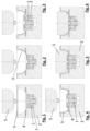
- Fig. 1-6 a method for producing a half-shell for a high-pressure vessel according to the invention is shown.
- a tool is used with a first tool half 2, which forms a die, and with a second tool half 5, which forms a punch.
- the tool therefore consists of two tool halves, whereby in the first tool half 2, preferably the lower tool half, the insert part is positioned on a movable holder 7.
- the second tool half 5 can also be equipped with a second insert part. With the help of sliders 4 provided in the tool and/or vacuum, the plastic is brought to the places necessary for the form fit.
- a preheated first plastic plate 3 is placed on the first tool half 2 and the first plastic plate 3 is sucked or pressed onto the first tool half 2 using negative pressure or pressure.
- the insert part 1, i.e. the boss part, is then positioned so that the plastic of the first plastic plate 3 is arranged in some areas behind an undercut, laterally spaced from the insert part 1.
- the movement of the insert part 1 can also be dispensed with, so that the plastic is immediately applied to a correctly positioned insert part 1, corresponding to Fig.3 , is sucked.
- the plastic of the first plastic plate 3 behind the undercut is pressed or sucked onto the insert part 1 at a laterally spaced distance from the insert part 1, so that a space behind the undercut of the insert part 1 is filled with the plastic.
- the second tool half 5 is moved onto the first tool half 2 to form the inner contour of the half-shell.
- the Fig. 1 to 6 The single sheet method shows the following steps in detail:
- one half of the tool namely the first tool half 2
- the insert part 1 - namely a boss part - and a preheated plastic plate 3.
- the insert part 1 is in the starting position.
- the second tool half 5 can also be equipped with another insert at this point.
- the plastic plate 3 is sucked into the first tool half 2, which represents the outer component geometry, using a vacuum.
- the insert part 1 is positioned in the first tool half 2 on a movable holder 7.
- the space behind the undercut of the component is filled - Fig. 3 and Fig. 4 .
- the second tool half 5 is lowered onto the first tool half 2 with a defined closing force and the inner contour of the component is reproduced.
- the insert part 1 can be returned to its starting position if necessary. This additionally presses the plastic behind the undercuts and increases the form fit between the insert part 1 and the plastic of the first plastic plate 3.
- FIG. 9 An alternative version of the manufacturing process is shown in the Fig. 9 to Fig. 14 , namely a twinsheet process for producing the half shell.
- both tool halves 2, 5 are each equipped with a preheated plastic plate 3, 6 ( Fig.9 ).
- the second tool half 5 can also be fitted with an insert at this point.
- the plastic plates 3, 6 are sucked into or onto the respective tool halves 2, 5 using a vacuum, which represent the outer or inner component geometry ( Fig.10 ).
- the insert part 1 to be enclosed is inserted into the first tool half 2 ( Fig. 11 ).
- Fig. 12 With the help of vacuum and/or sliders 4, the space behind the undercut of the insert 1 required for the form fit is filled with plastic ( Fig. 12 ). The excess material is cut off by cutting edges placed in the tool behind the undercut ( Fig. 13 ). These cutting edges can, as in Fig. 13 , also be included in the sliders 4.
- Fig. 14 shows the finished component, with the excess plastic, below the undercut and the slider 4, cut off.
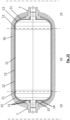
- a high-pressure vessel according to the invention is Fig. 15
- the high-pressure vessel comprises a cylinder 10 as a central part, wherein the cylinder 10 consists of a multi-layer composite plastic 11 which comprises a barrier layer 12, wherein the high-pressure vessel further comprises at least one half-shell 13 at an axial end of the cylinder 10, wherein the half-shell 13 consists of a multi-layer composite plastic 11 which comprises a barrier layer 12, wherein the half-shell 13 further comprises a substantially rotationally symmetrical insert part 1, namely a boss part, wherein the insert part 1 comprises an undercut with respect to demolding in the direction of the longitudinal center axis of the insert part 1, wherein the multi-layer composite plastic 11 of the half-shell 13 is arranged axially on both sides of the undercut of the insert part 1.
- the undercut is formed by a foot part 14 at the end of the insert part 1 facing the interior of the container, which has a larger diameter than a middle part of the insert part 1.
- the multi-layer composite plastic 11 is arranged axially on both sides of the foot part 14.
- the foot part 14 has several grooves 15 which are filled with the multilayer composite plastic 11 of the half shell 13.
- the insert part 1 essentially has the shape of a hollow cylinder.
- the base part 14 essentially has the shape of a hollow cone.
- a groove 15 filled with the multilayer composite plastic 11 of the half shell 13 runs around an inner circumference of the foot part 14.
- the multilayer composite plastic 11 of the cylinder 10 merges into the multilayer composite plastic 11 of the half-shell 13.
- the multilayer composite plastic 11 of the half-shell 13 as well as of the cylinder 10 comprises a layer of HDPE as the outermost layer and a barrier layer 12 of EVOH.
- the HDPE can be HDPE-S (black), after which a regranulate layer can be arranged, an adhesion promoter, the EVOH layer, optionally again an adhesion promoter and optionally also as the innermost layer again an HDPE layer.
- the high-pressure vessel comprises two half-shells 13 at the axial ends of the cylinder 10, wherein both half-shells 13 are designed as previously described, i.e. have a boss part 1 that is embedded in the multi-layer composite plastic 11.
- the cylinder 10 and the two half-shells 13 are wrapped with a fiber material 16, preferably with a composite material comprising carbon fibers and/or glass fibers and/or epoxy resin.
- a high-pressure vessel is specified that can be used to store gases under high pressure.
- This is designed as a lightweight construction and has a multi-part, multi-layer plastic liner consisting of two dome caps 13 and a cylinder 10, which ensures gas tightness and contains a permeation barrier 12.
- Boss parts 1, namely a "headstock” and a “tailstock”, are integrated into the two dome caps 13.
- the permeation properties are provided by a barrier layer 12 contained in the layer structure of the liner in both the dome caps 13 and the cylinder tube 10.
- the high-pressure vessel gets its mechanical strength from a fiber-reinforced composite 16, which is applied to the plastic liner in the winding process and then cured.
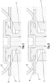
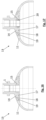
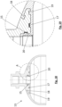
- Fig. 16 shows a half-shell 13 of a high-pressure container according to the invention.
- the half-shell 13 consists of a multi-layer composite plastic 11, which comprises a barrier layer 12, wherein the half-shell 13 further comprises a substantially rotationally symmetrical insert part 1, namely a boss part.
- the insert part 1 has a foot part 14 at the end of the insert part 1 facing the interior of the container, which has a larger diameter than a middle part of the insert part 1.
- the foot part 14 essentially forms a hollow cone.
- a first groove 15 filled with the multi-layer composite plastic 11 of the half-shell 13 runs around the inner circumference of the foot part 14.
- the multilayer composite plastic 11 of the half shell 13 is arranged axially on both sides of the foot part 14.
- the foot part 14 has a second groove 17 which is filled with the multilayer composite plastic 11 of the half-shell 13, wherein the second groove 17 runs near the inner circumference of the foot part 14 on the bottom of the foot part 14 facing the interior of the container.
- the foot part 14 has a third groove 18 which is filled with the multilayer composite plastic 11 of the half-shell 13, wherein the third groove 18 runs around the cover surface of the foot part 14 facing the outside of the container.
- the foot part 14 has a fourth groove 19 which is filled with the multilayer composite plastic 11 of the half-shell 13, wherein the fourth groove 19 runs near the outer circumference of the foot part 14 on the bottom of the foot part 14 facing the interior of the container.
- a sleeve 20 can be arranged radially within the first groove 15, within the inner circumference of the foot part 14, wherein the multi-layer composite plastic 11 of the half-shell 13 is pressed by the sleeve 20 against the inner circumference of the foot part 14 and into the first groove 15.
- a sealing element can be arranged at the bottom of the grooves, in particular the first groove 15 and the second groove 17.
- the primary sealing effect is achieved by pressing the plastic in the ring-circumferential grooves 15 and 17 on the metal base or in the core hole of the foot part of the boss part 1.
- Two further grooves 18, 19 on the outside of the plate or plate surface serve primarily to ensure positive locking and to stabilize the plastic-metal connection.
- a sleeve 20 can be inserted into the core hole during the manufacturing process in order to increase the compression on the sealing plastic material in the first groove 15.
- one or both sealing grooves 15, 17 - as in Fig. 19 shown - provided with an additional sealing element to increase the sealing effect in this area.
Landscapes
- Engineering & Computer Science (AREA)
- Mechanical Engineering (AREA)
- General Engineering & Computer Science (AREA)
- Filling Or Discharging Of Gas Storage Vessels (AREA)
- Pressure Vessels And Lids Thereof (AREA)
Priority Applications (1)
| Application Number | Priority Date | Filing Date | Title |
|---|---|---|---|
| EP24183320.1A EP4411198B1 (fr) | 2020-02-20 | 2020-02-20 | Récipient haute pression |
Applications Claiming Priority (2)
| Application Number | Priority Date | Filing Date | Title |
|---|---|---|---|
| EP24183320.1A EP4411198B1 (fr) | 2020-02-20 | 2020-02-20 | Récipient haute pression |
| EP20158504.9A EP3869081B1 (fr) | 2020-02-20 | 2020-02-20 | Réservoir haute pression |
Related Parent Applications (2)
| Application Number | Title | Priority Date | Filing Date |
|---|---|---|---|
| EP20158504.9A Division EP3869081B1 (fr) | 2020-02-20 | 2020-02-20 | Réservoir haute pression |
| EP20158504.9A Division-Into EP3869081B1 (fr) | 2020-02-20 | 2020-02-20 | Réservoir haute pression |
Publications (3)
| Publication Number | Publication Date |
|---|---|
| EP4411198A2 true EP4411198A2 (fr) | 2024-08-07 |
| EP4411198A3 EP4411198A3 (fr) | 2024-10-30 |
| EP4411198B1 EP4411198B1 (fr) | 2025-04-02 |
Family
ID=69845778
Family Applications (2)
| Application Number | Title | Priority Date | Filing Date |
|---|---|---|---|
| EP24183320.1A Active EP4411198B1 (fr) | 2020-02-20 | 2020-02-20 | Récipient haute pression |
| EP20158504.9A Active EP3869081B1 (fr) | 2020-02-20 | 2020-02-20 | Réservoir haute pression |
Family Applications After (1)
| Application Number | Title | Priority Date | Filing Date |
|---|---|---|---|
| EP20158504.9A Active EP3869081B1 (fr) | 2020-02-20 | 2020-02-20 | Réservoir haute pression |
Country Status (3)
| Country | Link |
|---|---|
| US (1) | US11598482B2 (fr) |
| EP (2) | EP4411198B1 (fr) |
| CN (1) | CN113280256B (fr) |
Families Citing this family (2)
| Publication number | Priority date | Publication date | Assignee | Title |
|---|---|---|---|---|
| JP2023066589A (ja) * | 2021-10-29 | 2023-05-16 | 豊田合成株式会社 | 高圧タンク |
| JP7782405B2 (ja) * | 2022-10-05 | 2025-12-09 | トヨタ自動車株式会社 | タンク及びタンクの製造方法 |
Citations (4)
| Publication number | Priority date | Publication date | Assignee | Title |
|---|---|---|---|---|
| JPH10332083A (ja) | 1997-05-28 | 1998-12-15 | Mitsubishi Chem Corp | 耐圧容器 |
| JPH10332085A (ja) | 1997-05-28 | 1998-12-15 | Mitsubishi Chem Corp | 耐圧容器 |
| US20080251520A1 (en) | 2007-04-06 | 2008-10-16 | Toyoda Gosei Co., Ltd. | Pressure vessel |
| US20190170300A1 (en) | 2016-06-28 | 2019-06-06 | Faber Industrie S.P.A. | Pressure recipient |
Family Cites Families (9)
| Publication number | Priority date | Publication date | Assignee | Title |
|---|---|---|---|---|
| DE10360953B4 (de) * | 2002-12-27 | 2011-04-07 | Toyoda Gosei Co., Ltd., Nishikasugai-gun | Druckbehälter |
| JP5179458B2 (ja) * | 2009-11-11 | 2013-04-10 | 八千代工業株式会社 | 圧力容器のシール構造 |
| PL226196B1 (pl) | 2014-01-15 | 2017-06-30 | Techplast Spółka Z Ograniczoną Odpowiedzialnością | Kompozytowy zbiornik wysokocisnieniowy oraz sposob wytwarzania kompozytowego zbiornika wysokocisnieniowego |
| AT516057B1 (de) * | 2014-03-12 | 2016-02-15 | Sedda Polstermöbelwerke Hans Thalermaier Gmbh | Beschlag für Sitz- und Liegemöbel |
| JP6356172B2 (ja) * | 2016-03-15 | 2018-07-11 | 本田技研工業株式会社 | 高圧タンク |
| JP6575414B2 (ja) * | 2016-03-29 | 2019-09-18 | 豊田合成株式会社 | 圧力容器 |
| KR101856334B1 (ko) | 2016-06-29 | 2018-05-09 | 현대자동차주식회사 | 기밀한 노즐 구조를 갖는 복합재 용기 |
| CN208546740U (zh) | 2017-12-31 | 2019-02-26 | 亚普汽车部件股份有限公司 | 一种高压复合容器塑料内胆的密封装置 |
| EP3919805B1 (fr) * | 2020-06-05 | 2023-11-29 | Magna Energy Storage Systems GesmbH | Réservoir haute pression |
-
2020
- 2020-02-20 EP EP24183320.1A patent/EP4411198B1/fr active Active
- 2020-02-20 EP EP20158504.9A patent/EP3869081B1/fr active Active
-
2021
- 2021-02-11 US US17/173,836 patent/US11598482B2/en active Active
- 2021-02-20 CN CN202110193521.3A patent/CN113280256B/zh not_active Expired - Fee Related
Patent Citations (4)
| Publication number | Priority date | Publication date | Assignee | Title |
|---|---|---|---|---|
| JPH10332083A (ja) | 1997-05-28 | 1998-12-15 | Mitsubishi Chem Corp | 耐圧容器 |
| JPH10332085A (ja) | 1997-05-28 | 1998-12-15 | Mitsubishi Chem Corp | 耐圧容器 |
| US20080251520A1 (en) | 2007-04-06 | 2008-10-16 | Toyoda Gosei Co., Ltd. | Pressure vessel |
| US20190170300A1 (en) | 2016-06-28 | 2019-06-06 | Faber Industrie S.P.A. | Pressure recipient |
Also Published As
| Publication number | Publication date |
|---|---|
| CN113280256B (zh) | 2023-03-31 |
| EP3869081A1 (fr) | 2021-08-25 |
| EP4411198A3 (fr) | 2024-10-30 |
| CN113280256A (zh) | 2021-08-20 |
| US11598482B2 (en) | 2023-03-07 |
| EP3869081B1 (fr) | 2024-09-04 |
| EP4411198B1 (fr) | 2025-04-02 |
| US20210262615A1 (en) | 2021-08-26 |
Similar Documents
| Publication | Publication Date | Title |
|---|---|---|
| EP1084889B1 (fr) | Insert de reservoir et méthode pour sa fabrication | |
| DE10360953B4 (de) | Druckbehälter | |
| EP3786511B1 (fr) | Récipient sous pression | |
| DE2932375C2 (de) | Verfahren zum Herstellen eines Verpackungsbehälters | |
| EP1894702B1 (fr) | Procédé destiné à la fabrication d'un récipient de combustible | |
| DE60112408T2 (de) | Verfahren zur herstellung eines kunststoff-kraftstofftanks | |
| DE102011116553A1 (de) | Verfahren zur Herstellung eines Verbund-Druckbehälters sowie Verbund-Druckbehälter | |
| EP3919805B1 (fr) | Réservoir haute pression | |
| EP3919804B1 (fr) | Réservoir haute pression | |
| EP3869081B1 (fr) | Réservoir haute pression | |
| WO2011000504A2 (fr) | Procédé de fabrication d'un article en plastique thermoplastique | |
| DE19711844B4 (de) | Verfahren zum Herstellen eines Druckgasbehälters | |
| DE102012020949A1 (de) | Verfahren zur Herstellung eines Behälters aus thermoplastischem Kunststoff | |
| CH696115A5 (de) | Verpackungsbehälter. | |
| JPH09242990A (ja) | 高圧容器ライナー用成形品及びその製造方法 | |
| EP1574442B1 (fr) | Procédé pour la fabrication d'un fût en matière thermoplastique | |
| EP4030095A1 (fr) | Procédé de fabrication d'un corps creux | |
| DE10064801A1 (de) | Verfahren zur Herstellung von Kunststoffhohlkörpern | |
| EP3868543B1 (fr) | Procédé de fabrication d'un demi-coque | |
| DE102016222674A1 (de) | Verfahren zum Herstellen eines Druckbehälters, Druckbehälter und Rohrextrusionsanlage | |
| EP3869082A1 (fr) | Réservoir haute pression | |
| EP1631469B1 (fr) | Tube de remplissage en plastique forme par extrusion-soufflage | |
| EP2771561B1 (fr) | Silencieux pour conduites d'air d'un moteur à combustion interne doté d'un turbocompresseur et procédé pour sa fabrication | |
| WO2017186387A1 (fr) | Tubulure de remplissage pour réservoir à carburant | |
| EP1993938B1 (fr) | Récipient à double paroi |
Legal Events
| Date | Code | Title | Description |
|---|---|---|---|
| PUAI | Public reference made under article 153(3) epc to a published international application that has entered the european phase |
Free format text: ORIGINAL CODE: 0009012 |
|
| STAA | Information on the status of an ep patent application or granted ep patent |
Free format text: STATUS: THE APPLICATION HAS BEEN PUBLISHED |
|
| AC | Divisional application: reference to earlier application |
Ref document number: 3869081 Country of ref document: EP Kind code of ref document: P |
|
| AK | Designated contracting states |
Kind code of ref document: A2 Designated state(s): AL AT BE BG CH CY CZ DE DK EE ES FI FR GB GR HR HU IE IS IT LI LT LU LV MC MK MT NL NO PL PT RO RS SE SI SK SM TR |
|
| REG | Reference to a national code |
Ref country code: DE Ref legal event code: R079 Free format text: PREVIOUS MAIN CLASS: F17C0001060000 Ipc: F17C0013040000 Ref document number: 502020010774 Country of ref document: DE |
|
| PUAL | Search report despatched |
Free format text: ORIGINAL CODE: 0009013 |
|
| AK | Designated contracting states |
Kind code of ref document: A3 Designated state(s): AL AT BE BG CH CY CZ DE DK EE ES FI FR GB GR HR HU IE IS IT LI LT LU LV MC MK MT NL NO PL PT RO RS SE SI SK SM TR |
|
| RIC1 | Information provided on ipc code assigned before grant |
Ipc: F17C 1/06 20060101ALN20240925BHEP Ipc: F17C 13/04 20060101AFI20240925BHEP |
|
| STAA | Information on the status of an ep patent application or granted ep patent |
Free format text: STATUS: REQUEST FOR EXAMINATION WAS MADE |
|
| 17P | Request for examination filed |
Effective date: 20241028 |
|
| RBV | Designated contracting states (corrected) |
Designated state(s): AL AT BE BG CH CY CZ DE DK EE ES FI FR GB GR HR HU IE IS IT LI LT LU LV MC MK MT NL NO PL PT RO RS SE SI SK SM TR |
|
| GRAP | Despatch of communication of intention to grant a patent |
Free format text: ORIGINAL CODE: EPIDOSNIGR1 |
|
| STAA | Information on the status of an ep patent application or granted ep patent |
Free format text: STATUS: GRANT OF PATENT IS INTENDED |
|
| RIC1 | Information provided on ipc code assigned before grant |
Ipc: F17C 1/06 20060101ALN20241209BHEP Ipc: F17C 13/04 20060101AFI20241209BHEP |
|
| INTG | Intention to grant announced |
Effective date: 20250113 |
|
| GRAS | Grant fee paid |
Free format text: ORIGINAL CODE: EPIDOSNIGR3 |
|
| GRAA | (expected) grant |
Free format text: ORIGINAL CODE: 0009210 |
|
| STAA | Information on the status of an ep patent application or granted ep patent |
Free format text: STATUS: THE PATENT HAS BEEN GRANTED |
|
| AC | Divisional application: reference to earlier application |
Ref document number: 3869081 Country of ref document: EP Kind code of ref document: P |
|
| AK | Designated contracting states |
Kind code of ref document: B1 Designated state(s): AL AT BE BG CH CY CZ DE DK EE ES FI FR GB GR HR HU IE IS IT LI LT LU LV MC MK MT NL NO PL PT RO RS SE SI SK SM TR |
|
| REG | Reference to a national code |
Ref country code: GB Ref legal event code: FG4D Free format text: NOT ENGLISH |
|
| REG | Reference to a national code |
Ref country code: CH Ref legal event code: EP |
|
| REG | Reference to a national code |
Ref country code: DE Ref legal event code: R096 Ref document number: 502020010774 Country of ref document: DE |
|
| REG | Reference to a national code |
Ref country code: IE Ref legal event code: FG4D Free format text: LANGUAGE OF EP DOCUMENT: GERMAN |
|
| REG | Reference to a national code |
Ref country code: NL Ref legal event code: MP Effective date: 20250402 |
|
| PG25 | Lapsed in a contracting state [announced via postgrant information from national office to epo] |
Ref country code: NL Free format text: LAPSE BECAUSE OF FAILURE TO SUBMIT A TRANSLATION OF THE DESCRIPTION OR TO PAY THE FEE WITHIN THE PRESCRIBED TIME-LIMIT Effective date: 20250402 |
|
| PG25 | Lapsed in a contracting state [announced via postgrant information from national office to epo] |
Ref country code: FI Free format text: LAPSE BECAUSE OF FAILURE TO SUBMIT A TRANSLATION OF THE DESCRIPTION OR TO PAY THE FEE WITHIN THE PRESCRIBED TIME-LIMIT Effective date: 20250402 Ref country code: ES Free format text: LAPSE BECAUSE OF FAILURE TO SUBMIT A TRANSLATION OF THE DESCRIPTION OR TO PAY THE FEE WITHIN THE PRESCRIBED TIME-LIMIT Effective date: 20250402 Ref country code: PT Free format text: LAPSE BECAUSE OF FAILURE TO SUBMIT A TRANSLATION OF THE DESCRIPTION OR TO PAY THE FEE WITHIN THE PRESCRIBED TIME-LIMIT Effective date: 20250804 |
|
| REG | Reference to a national code |
Ref country code: LT Ref legal event code: MG9D |
|
| PG25 | Lapsed in a contracting state [announced via postgrant information from national office to epo] |
Ref country code: NO Free format text: LAPSE BECAUSE OF FAILURE TO SUBMIT A TRANSLATION OF THE DESCRIPTION OR TO PAY THE FEE WITHIN THE PRESCRIBED TIME-LIMIT Effective date: 20250702 Ref country code: GR Free format text: LAPSE BECAUSE OF FAILURE TO SUBMIT A TRANSLATION OF THE DESCRIPTION OR TO PAY THE FEE WITHIN THE PRESCRIBED TIME-LIMIT Effective date: 20250703 |
|
| PG25 | Lapsed in a contracting state [announced via postgrant information from national office to epo] |
Ref country code: PL Free format text: LAPSE BECAUSE OF FAILURE TO SUBMIT A TRANSLATION OF THE DESCRIPTION OR TO PAY THE FEE WITHIN THE PRESCRIBED TIME-LIMIT Effective date: 20250402 |
|
| PG25 | Lapsed in a contracting state [announced via postgrant information from national office to epo] |
Ref country code: BG Free format text: LAPSE BECAUSE OF FAILURE TO SUBMIT A TRANSLATION OF THE DESCRIPTION OR TO PAY THE FEE WITHIN THE PRESCRIBED TIME-LIMIT Effective date: 20250402 |
|
| PG25 | Lapsed in a contracting state [announced via postgrant information from national office to epo] |
Ref country code: HR Free format text: LAPSE BECAUSE OF FAILURE TO SUBMIT A TRANSLATION OF THE DESCRIPTION OR TO PAY THE FEE WITHIN THE PRESCRIBED TIME-LIMIT Effective date: 20250402 |
|
| PG25 | Lapsed in a contracting state [announced via postgrant information from national office to epo] |
Ref country code: RS Free format text: LAPSE BECAUSE OF FAILURE TO SUBMIT A TRANSLATION OF THE DESCRIPTION OR TO PAY THE FEE WITHIN THE PRESCRIBED TIME-LIMIT Effective date: 20250702 |
|
| PG25 | Lapsed in a contracting state [announced via postgrant information from national office to epo] |
Ref country code: IS Free format text: LAPSE BECAUSE OF FAILURE TO SUBMIT A TRANSLATION OF THE DESCRIPTION OR TO PAY THE FEE WITHIN THE PRESCRIBED TIME-LIMIT Effective date: 20250802 |
|
| PG25 | Lapsed in a contracting state [announced via postgrant information from national office to epo] |
Ref country code: LV Free format text: LAPSE BECAUSE OF FAILURE TO SUBMIT A TRANSLATION OF THE DESCRIPTION OR TO PAY THE FEE WITHIN THE PRESCRIBED TIME-LIMIT Effective date: 20250402 |
|
| REG | Reference to a national code |
Ref country code: DE Ref legal event code: R097 Ref document number: 502020010774 Country of ref document: DE |
|
| PG25 | Lapsed in a contracting state [announced via postgrant information from national office to epo] |
Ref country code: SM Free format text: LAPSE BECAUSE OF FAILURE TO SUBMIT A TRANSLATION OF THE DESCRIPTION OR TO PAY THE FEE WITHIN THE PRESCRIBED TIME-LIMIT Effective date: 20250402 Ref country code: DK Free format text: LAPSE BECAUSE OF FAILURE TO SUBMIT A TRANSLATION OF THE DESCRIPTION OR TO PAY THE FEE WITHIN THE PRESCRIBED TIME-LIMIT Effective date: 20250402 |
|
| PG25 | Lapsed in a contracting state [announced via postgrant information from national office to epo] |
Ref country code: CZ Free format text: LAPSE BECAUSE OF FAILURE TO SUBMIT A TRANSLATION OF THE DESCRIPTION OR TO PAY THE FEE WITHIN THE PRESCRIBED TIME-LIMIT Effective date: 20250402 |
|
| PG25 | Lapsed in a contracting state [announced via postgrant information from national office to epo] |
Ref country code: EE Free format text: LAPSE BECAUSE OF FAILURE TO SUBMIT A TRANSLATION OF THE DESCRIPTION OR TO PAY THE FEE WITHIN THE PRESCRIBED TIME-LIMIT Effective date: 20250402 |
|
| PG25 | Lapsed in a contracting state [announced via postgrant information from national office to epo] |
Ref country code: SK Free format text: LAPSE BECAUSE OF FAILURE TO SUBMIT A TRANSLATION OF THE DESCRIPTION OR TO PAY THE FEE WITHIN THE PRESCRIBED TIME-LIMIT Effective date: 20250402 |
|
| PG25 | Lapsed in a contracting state [announced via postgrant information from national office to epo] |
Ref country code: IT Free format text: LAPSE BECAUSE OF FAILURE TO SUBMIT A TRANSLATION OF THE DESCRIPTION OR TO PAY THE FEE WITHIN THE PRESCRIBED TIME-LIMIT Effective date: 20250402 |
|
| PLBE | No opposition filed within time limit |
Free format text: ORIGINAL CODE: 0009261 |
|
| STAA | Information on the status of an ep patent application or granted ep patent |
Free format text: STATUS: NO OPPOSITION FILED WITHIN TIME LIMIT |
|
| REG | Reference to a national code |
Ref country code: CH Ref legal event code: L10 Free format text: ST27 STATUS EVENT CODE: U-0-0-L10-L00 (AS PROVIDED BY THE NATIONAL OFFICE) Effective date: 20260211 |
|
| 26N | No opposition filed |
Effective date: 20260105 |
|
| PGFP | Annual fee paid to national office [announced via postgrant information from national office to epo] |
Ref country code: DE Payment date: 20260218 Year of fee payment: 7 |
|
| PGFP | Annual fee paid to national office [announced via postgrant information from national office to epo] |
Ref country code: FR Payment date: 20260219 Year of fee payment: 7 |
|
| PG25 | Lapsed in a contracting state [announced via postgrant information from national office to epo] |
Ref country code: LT Free format text: LAPSE BECAUSE OF FAILURE TO SUBMIT A TRANSLATION OF THE DESCRIPTION OR TO PAY THE FEE WITHIN THE PRESCRIBED TIME-LIMIT Effective date: 20250402 |
|
| PG25 | Lapsed in a contracting state [announced via postgrant information from national office to epo] |
Ref country code: SE Free format text: LAPSE BECAUSE OF FAILURE TO SUBMIT A TRANSLATION OF THE DESCRIPTION OR TO PAY THE FEE WITHIN THE PRESCRIBED TIME-LIMIT Effective date: 20250402 |