EP1084889B1 - Insert de reservoir et méthode pour sa fabrication - Google Patents
Insert de reservoir et méthode pour sa fabrication Download PDFInfo
- Publication number
- EP1084889B1 EP1084889B1 EP00117409A EP00117409A EP1084889B1 EP 1084889 B1 EP1084889 B1 EP 1084889B1 EP 00117409 A EP00117409 A EP 00117409A EP 00117409 A EP00117409 A EP 00117409A EP 1084889 B1 EP1084889 B1 EP 1084889B1
- Authority
- EP
- European Patent Office
- Prior art keywords
- insert
- thermoplastic material
- tank
- connection
- fuel tank
- Prior art date
- Legal status (The legal status is an assumption and is not a legal conclusion. Google has not performed a legal analysis and makes no representation as to the accuracy of the status listed.)
- Expired - Lifetime
Links
Images


Classifications
-
- B—PERFORMING OPERATIONS; TRANSPORTING
- B60—VEHICLES IN GENERAL
- B60K—ARRANGEMENT OR MOUNTING OF PROPULSION UNITS OR OF TRANSMISSIONS IN VEHICLES; ARRANGEMENT OR MOUNTING OF PLURAL DIVERSE PRIME-MOVERS IN VEHICLES; AUXILIARY DRIVES FOR VEHICLES; INSTRUMENTATION OR DASHBOARDS FOR VEHICLES; ARRANGEMENTS IN CONNECTION WITH COOLING, AIR INTAKE, GAS EXHAUST OR FUEL SUPPLY OF PROPULSION UNITS IN VEHICLES
- B60K15/00—Arrangement in connection with fuel supply of combustion engines or other fuel consuming energy converters, e.g. fuel cells; Mounting or construction of fuel tanks
- B60K15/03—Fuel tanks
- B60K15/035—Fuel tanks characterised by venting means
- B60K15/03519—Valve arrangements in the vent line
-
- B—PERFORMING OPERATIONS; TRANSPORTING
- B60—VEHICLES IN GENERAL
- B60K—ARRANGEMENT OR MOUNTING OF PROPULSION UNITS OR OF TRANSMISSIONS IN VEHICLES; ARRANGEMENT OR MOUNTING OF PLURAL DIVERSE PRIME-MOVERS IN VEHICLES; AUXILIARY DRIVES FOR VEHICLES; INSTRUMENTATION OR DASHBOARDS FOR VEHICLES; ARRANGEMENTS IN CONNECTION WITH COOLING, AIR INTAKE, GAS EXHAUST OR FUEL SUPPLY OF PROPULSION UNITS IN VEHICLES
- B60K15/00—Arrangement in connection with fuel supply of combustion engines or other fuel consuming energy converters, e.g. fuel cells; Mounting or construction of fuel tanks
- B60K15/03—Fuel tanks
- B60K15/03177—Fuel tanks made of non-metallic material, e.g. plastics, or of a combination of non-metallic and metallic material
-
- B—PERFORMING OPERATIONS; TRANSPORTING
- B60—VEHICLES IN GENERAL
- B60K—ARRANGEMENT OR MOUNTING OF PROPULSION UNITS OR OF TRANSMISSIONS IN VEHICLES; ARRANGEMENT OR MOUNTING OF PLURAL DIVERSE PRIME-MOVERS IN VEHICLES; AUXILIARY DRIVES FOR VEHICLES; INSTRUMENTATION OR DASHBOARDS FOR VEHICLES; ARRANGEMENTS IN CONNECTION WITH COOLING, AIR INTAKE, GAS EXHAUST OR FUEL SUPPLY OF PROPULSION UNITS IN VEHICLES
- B60K15/00—Arrangement in connection with fuel supply of combustion engines or other fuel consuming energy converters, e.g. fuel cells; Mounting or construction of fuel tanks
- B60K15/03—Fuel tanks
- B60K2015/03032—Manufacturing of fuel tanks
- B60K2015/03046—Manufacturing of fuel tanks made from more than one layer
-
- B—PERFORMING OPERATIONS; TRANSPORTING
- B60—VEHICLES IN GENERAL
- B60K—ARRANGEMENT OR MOUNTING OF PROPULSION UNITS OR OF TRANSMISSIONS IN VEHICLES; ARRANGEMENT OR MOUNTING OF PLURAL DIVERSE PRIME-MOVERS IN VEHICLES; AUXILIARY DRIVES FOR VEHICLES; INSTRUMENTATION OR DASHBOARDS FOR VEHICLES; ARRANGEMENTS IN CONNECTION WITH COOLING, AIR INTAKE, GAS EXHAUST OR FUEL SUPPLY OF PROPULSION UNITS IN VEHICLES
- B60K15/00—Arrangement in connection with fuel supply of combustion engines or other fuel consuming energy converters, e.g. fuel cells; Mounting or construction of fuel tanks
- B60K15/03—Fuel tanks
- B60K2015/03328—Arrangements or special measures related to fuel tanks or fuel handling
- B60K2015/03447—Arrangements or special measures related to fuel tanks or fuel handling for improving the sealing
-
- B—PERFORMING OPERATIONS; TRANSPORTING
- B60—VEHICLES IN GENERAL
- B60K—ARRANGEMENT OR MOUNTING OF PROPULSION UNITS OR OF TRANSMISSIONS IN VEHICLES; ARRANGEMENT OR MOUNTING OF PLURAL DIVERSE PRIME-MOVERS IN VEHICLES; AUXILIARY DRIVES FOR VEHICLES; INSTRUMENTATION OR DASHBOARDS FOR VEHICLES; ARRANGEMENTS IN CONNECTION WITH COOLING, AIR INTAKE, GAS EXHAUST OR FUEL SUPPLY OF PROPULSION UNITS IN VEHICLES
- B60K15/00—Arrangement in connection with fuel supply of combustion engines or other fuel consuming energy converters, e.g. fuel cells; Mounting or construction of fuel tanks
- B60K15/03—Fuel tanks
- B60K2015/03328—Arrangements or special measures related to fuel tanks or fuel handling
- B60K2015/03453—Arrangements or special measures related to fuel tanks or fuel handling for fixing or mounting parts of the fuel tank together
- B60K2015/03467—Arrangements or special measures related to fuel tanks or fuel handling for fixing or mounting parts of the fuel tank together by clip or snap fit fittings
Definitions
- the invention relates to an insert made of thermoplastic Material for connection to a hollow body made of thermoplastic Material, especially as a connection opening of a Fuel tank lining and / or a seat for one Component forming the connecting element.
- a fuel tank lining and / or a seat for one Component forming the connecting element Such use is over the generic document US-A-5 404 907 is known.
- Valves and connecting pieces come as connection elements as well as nipples. Furthermore, a Connection opening of the tank to accommodate a conveyor unit or as a so-called transmitter opening (level indicator) or also be designed as an insertion tube connection.
- connection openings are problematic in this respect in the tank, which has a sealing seat for nozzles, valves and the like form. Since such openings are closely tolerated have to, for example, a sufficiently sealing and play-free seat of a connecting piece or a valve guarantee, it is not possible in many cases Valve seat or sealing seat for the connection component in one Operation in the manufacture (extrusion blow molding) of the tank to provide with.
- An opening is therefore provided in the tank as a connection opening.
- a valve sealingly into this opening.
- the valve against the Screw the tank wall of adjacent seals against the tank wall. This measure is increased for fuel tanks Tightness requirements for the tank unsuitable.
- Welding the valve to the tank is straightforward also not considered, since valves and connecting pieces in generally because of the fuel resistance of the Materials are made of POM (polyoxymethylene), whereas the Tank is at least partially made of PE (polyethylene); the different materials cannot be welded together.
- valves or nipples made of POM are also used a PE injection molded shaft in which the valve or the connection nipple can be clipped on.
- the shaft can then in the connection opening of the tank with this are welded, for example in the heating element welding process.
- the latter approach still has the disadvantage that the connection opening of the tank with regard to a possible emission of hydrocarbons a weak point represents because PE (polyethylene) is permeable to hydrocarbons and swells when they are present, whereas POM (polyoxymethylene) is hardly permeable to hydrocarbons.
- a connection opening in the tank is therefore still a Emission source.
- the invention is therefore based on the object, one in one To create a connecting element to be inserted, in particular an application of the type mentioned at the beginning as Use for a connection opening to create its permeability for hydrocarbons is reduced so that the total hydrocarbon emissions of a fuel tank the known tanks is reduced.
- the use is expediently cohesive with the Connectable fuel tank, preferably weldable to it, which is particularly guaranteed when the application is made of the same laminate as the tank.
- the heating element welding process is preferred.
- barrier layers Preferably two barrier layers are provided.
- the barrier layers can be made in an essentially made of polyethylene Be embedded. It is ensured that the Base body can be welded to the material of the tank.
- the Barrier layers should run in the material be arranged so that when welding the insert with the tank as close as possible to those running in the tank wall Connect barrier layers. Otherwise it is desirable if the barrier layers in the Run near the inner wall of the insert at an angle to the longitudinal axis of the insert, so that migration of fuel largely avoided around the barrier layer becomes.
- the barrier layers consist of EVOH (ethylene vinyl alcohol).
- EVOH ethylene vinyl alcohol
- a co-extrusion blow molded Container is known for example from DE 43 37 491 A1.
- the object underlying the invention will continue solved by a method according to claim 6.
- the finished insert receives one or more barrier layers.
- the course of the barrier layers is in the use also depends on the design of the press tool, for example on the position of the tool division or the closing or pinching points of the tool.
- a multi-layer preform is preferably co-extruded and by pressing it into its final heat Formed.
- the preform is in the form of a Hose is extruded, its opposite walls are pressed together in the mold.
- a Hose is also used, for example, to manufacture the tank extruded so that the insert ultimately matches the same Extrusion technology can be produced, only another Tool is required.
- Press molding in the sense of the invention is the molding of a soften thermoplastic material, either as an extrudate or as a softened semi-finished product, preferably in a multi-part two-part form, consisting of stamp and die, to be understood.
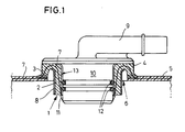
- the insert 1 is in accordance with the invention as a hollow cylindrical, annular element a cylindrical section 2 and a support flange 3 forming collar 4 formed.
- the wall is one in the co-extrusion blow molding process Manufactured fuel tanks with which the Collar 4 of the insert 1 in the peripheral area of a connection opening 6 is welded.
- the wall 5 of the fuel tank consists of a difficultly permeable to hydrocarbons Laminate with a barrier layer 7 made of EVOH (ethylene vinyl alcohol).
- the barrier layer 7 blocks against the passage of hydrocarbons through the wall 5 of the tank.
- the insert 1 shown in FIGS. 1 and 2 exists according to the invention also from a hydrocarbon heavily permeable laminate with a barrier layer 7.
- the in 1 and 2 different embodiments shown to the extent that the course of the Barrier layer 7 is selected differently there.
- the Barrier layer 7 in the area of the cylindrical section 2 of the insert 1 at an angle to the longitudinal axis of the insert 1 and is located at the bottom of the cylindrical Section 2 near its inner wall 13.
- the barrier layer is slightly above of the support flange 3.
- the barrier layer 7 ideally runs initially as close as possible to and parallel to the inner wall 13 of the Insert 1.
- the barrier layer runs in the area of the collar 4 7 as close as possible to the outside of the insert 1 and ends almost exactly in the outer corner area of the support flange Third
- insert 1 In the third embodiment shown in FIG. 3 of insert 1 according to the invention are a total of two barrier layers 7 provided.
- the exact layer structure of the Insert 1 according to the embodiment shown in FIG. 3 results from FIG. 7.
- the insert 1 Since the base material of the insert 1 as well as the tank is polyethylene which is in the presence of hydrocarbons swells, the insert 1 has a metal support ring 8 provided that a change in shape in the sense of an increase in diameter use 1 due to the absorption of hydrocarbons prevents and the insert 1 like a cuff surrounds. Should use 1 due to the presence swell of hydrocarbons, this can because of the Presence of the metal support ring 8 only inwards dodge so that the connection with the wall 5 of the tank is not affected. This is also experienced in action located part, e.g. B. a valve or another Part, with regard to its seat in use and the associated Sealing no adverse effects.
- a metal support ring 8 provided that a change in shape in the sense of an increase in diameter use 1 due to the absorption of hydrocarbons prevents and the insert 1 like a cuff surrounds. Should use 1 due to the presence swell of hydrocarbons, this can because of the Presence of the metal support ring 8 only in
- the Insert 1 as a sealing seat for a valve 9 made of POM (polyoxymethylene).
- the valve 9 has a cylindrical base body 10, the outer contour and the outer diameter of which corresponds to the inner contour and the inner diameter of the insert, with a relatively high degree of dimensional accuracy.
- the base body 10 of the valve 9 cannot be detached via latching lugs 11 locked with insert 1.
- the valve 9 is against Insert 1 sealed by means of two O-ring seals 12, being one of the O-ring seals for the low temperature range and the other is for the high temperature range.
- the Barrier layer 7 in the area of the support flange 3 if possible far outside in order to weld the support flange 3 to the Wall 5 of the tank a connection of the barrier layer 7 of the Insert 1 to ensure the barrier layer 7 of the wall 5.
- the barrier layer 7 should be in the Base material of the insert 1 to be embedded in front of physical Injuries to be protected.
- the insert 1 shown in Fig. 4 takes one instead Valve on an elbow made of POM (polyoxymethylene). at all of the illustrated embodiments are proportional reproduced simple variant of the insert 1, the has a smooth inner wall 13, either the elbow 14 or the valve 9 cannot be detached from the insert 1 are locked. It is also conceivable to use the insert 1 with a to equip profiled inner walls, for example in shape of a thread, so that the relevant connecting element with the Insert 1 is screwable.
- 5 and 6 is the process of making the insert 1 is shown schematically.
- a two part Tool consisting of stamp 16 and die 17 designated which forms the mold for the production of the insert.
- the insert 1 by extruding a multi-layer hose 18 is produced in the co-extrusion process, the tube 18 is inserted into the open tool 15 (see FIG. 5).
- the parts of the tool 15, i.e. H. the stamp 16 and the die 17 are moved towards one another, the hose 18 fills the cavity 19 of the tool 15.
- the Die 17 and the punch 16 applied closing forces the excess material is partially squeezed out and partially driven into the equalization room 20.
- the preferred six layers of co-extruded tubing becomes one a total of twelve-layer structures pressed together.
- the finished insert has the one shown schematically in FIG. 7 Construction from a total of twelve parallel layers, of which the two outer layers 21, for example made of polyethylene consist of layers of regenerate 22 on. Recycled material is closed under regenerate 22 understand what, for example, in the manufacture of the tank or container or in the manufacture of the insert 1 as Waste material (scrap) has accrued.
- the barrier layers made of EVOH (ethylene vinyl alcohol) 7 are each in an adhesion promoter layer 23 embedded with which a connection of the barrier layers with the regenerate 22 or the outer layers 21 made of polyethylene is guaranteed.
- EVOH ethylene vinyl alcohol
Landscapes
- Engineering & Computer Science (AREA)
- Life Sciences & Earth Sciences (AREA)
- Sustainable Development (AREA)
- Sustainable Energy (AREA)
- Chemical & Material Sciences (AREA)
- Combustion & Propulsion (AREA)
- Transportation (AREA)
- Mechanical Engineering (AREA)
- Blow-Moulding Or Thermoforming Of Plastics Or The Like (AREA)
- Cooling, Air Intake And Gas Exhaust, And Fuel Tank Arrangements In Propulsion Units (AREA)
- Laminated Bodies (AREA)
- Casting Or Compression Moulding Of Plastics Or The Like (AREA)
Claims (9)
- Insert en matériau thermoplastique pour réaliser une liaison avec un corps creux en matériau thermoplastique, en particulier comme composant servant à revêtir une ouverture de raccordement d'un réservoir de carburant et/ou formant un siège pour un élément de raccordement, caractérisé en ce que l'insert (1) a été obtenu par un moulage sous pression d'un aggloméré laminé difficilement perméable aux hydrocarbures, en ce que l'insert se compose d'un aggloméré laminé avec au moins une couche de barrage (7) pour les hydrocarbures et en ce que la couche de barrage (7) se compose d'alcool de vinyle d'éthylène.
- Insert selon la revendication 1, caractérisé en ce que l'insert (1) peut être relié en complémentarité de matière avec le réservoir de carburant, de préférence être soudé avec celui-ci.
- Insert selon l'une quelconque des revendications 1 ou 2, caractérisé en ce que la couche de barrage (7) ou les couches de barrage (7) est(sont) enrobée(s) presque entièrement dans le matériau de l'insert (1), de préférence en s'étendant au moins dans la zone d'un tronçon cylindrique (2) de l'insert (1) à proximité de sa paroi intérieure (13).
- Insert selon l'une quelconque des revendications 1 à 3, caractérisé en ce que deux couches de barrage (7) sont prévues.
- Insert selon l'une quelconque des revendications 1 à 4, caractérisé en ce que les couches de barrage (7) sont enrobées dans un corps de base se composant pour l'essentiel de polyéthylène.
- Procédé pour la réalisation d'un insert pour assurer une liaison étanche et non détachable avec un réservoir de carburant en matériau thermoplastique, caractérisé en ce que l'insert est obtenu dans un moule en plusieurs parties par un moulage sous pression d'un matériau thermoplastique ramolli comme produit d'extrusion ou comme produit semi-fini sous la forme d'un aggloméré laminé difficilement perméable aux hydrocarbures.
- Procédé selon la revendication 6, caractérisé par une co-extrusion d'une préforme multicouche et par un pressage de la préforme sous la première chaleur jusqu'à la forme définitive.
- Procédé selon l'une quelconque des revendications 6 ou 7, caractérisé en ce que la préforme est extrudée sous la forme d'un tuyau dont les parois opposées sont pressées l'une contre l'autre dans le moule sous pression.
- Corps creux en matériau thermoplastique, en particulier réservoir de carburant, avec un insert ayant les caractéristiques de l'une quelconque des revendications 1 à 5.
Applications Claiming Priority (2)
| Application Number | Priority Date | Filing Date | Title |
|---|---|---|---|
| DE19943673A DE19943673A1 (de) | 1999-09-13 | 1999-09-13 | Tankeinsatz und Verfahren zu dessen Herstellung |
| DE19943673 | 1999-09-13 |
Publications (2)
| Publication Number | Publication Date |
|---|---|
| EP1084889A1 EP1084889A1 (fr) | 2001-03-21 |
| EP1084889B1 true EP1084889B1 (fr) | 2004-06-09 |
Family
ID=7921750
Family Applications (1)
| Application Number | Title | Priority Date | Filing Date |
|---|---|---|---|
| EP00117409A Expired - Lifetime EP1084889B1 (fr) | 1999-09-13 | 2000-08-11 | Insert de reservoir et méthode pour sa fabrication |
Country Status (7)
| Country | Link |
|---|---|
| US (1) | US20040124567A1 (fr) |
| EP (1) | EP1084889B1 (fr) |
| JP (1) | JP3528154B2 (fr) |
| AT (1) | ATE268704T1 (fr) |
| CA (1) | CA2318653A1 (fr) |
| DE (2) | DE19943673A1 (fr) |
| ES (1) | ES2220304T3 (fr) |
Cited By (2)
| Publication number | Priority date | Publication date | Assignee | Title |
|---|---|---|---|---|
| US6915812B2 (en) | 2000-09-12 | 2005-07-12 | Alfmeier Corporation | Low permeation weldable fuel tank assembly |
| US6966330B2 (en) | 2003-08-27 | 2005-11-22 | Alfmeier Corporation | Weldring with locking arrangement for valve assembly |
Families Citing this family (27)
| Publication number | Priority date | Publication date | Assignee | Title |
|---|---|---|---|---|
| US6652699B1 (en) | 2000-02-17 | 2003-11-25 | Salflex Polymers Ltd. | Flanged member with barrier layer |
| US6860398B2 (en) * | 2000-11-30 | 2005-03-01 | Visteon Global Technologies, Inc. | Low permeation fittings, low permeation containers utilizing same, and methods for forming same |
| AT4938U1 (de) | 2001-01-19 | 2002-01-25 | Tesma Motoren Getriebetechnik | Kraftstoffbehälter mit deckel |
| US6669043B2 (en) * | 2001-09-27 | 2003-12-30 | Visteon Global Technologies, Inc. | Passthru device for internalized component fuel tanks |
| DE10328961A1 (de) * | 2003-06-27 | 2005-01-13 | Volkswagen Ag | Kraftstoffversorgungsanlage für eine Brennkraftmaschine |
| JP2005090595A (ja) * | 2003-09-16 | 2005-04-07 | Mitsubishi Plastics Ind Ltd | 電気融着継手及びその製造方法 |
| US7565986B2 (en) * | 2003-12-02 | 2009-07-28 | Ti Group Automotive Systems, L.L.C. | Fuel system component and method of manufacture |
| US7704440B2 (en) * | 2003-12-02 | 2010-04-27 | Ti Group Automotive Systems, L.L.C. | Fuel system component and method of manufacture |
| JP4442325B2 (ja) * | 2004-05-31 | 2010-03-31 | 東洋製罐株式会社 | 多層構造体の製造方法 |
| KR101280334B1 (ko) * | 2004-11-30 | 2013-07-01 | 티아이 그룹 오토모티브 시스템즈 엘엘씨 | 연료 시스템 구성요소 및 그의 제조 방법 |
| DE102005042678B4 (de) * | 2004-12-24 | 2025-07-17 | Norma Germany Gmbh | Verfahren zur Herstellung eines Stutzens |
| JP4991172B2 (ja) | 2006-03-27 | 2012-08-01 | 株式会社ニフコ | 燃料タンク用コネクタ |
| JP5010294B2 (ja) * | 2007-01-22 | 2012-08-29 | エクセル株式会社 | プラスチック中空成形体の壁に形成した透孔の封止構造 |
| JP2008201365A (ja) * | 2007-02-22 | 2008-09-04 | Tokai Rubber Ind Ltd | 樹脂製燃料タンク用接合部品およびその製法 |
| US20080314670A1 (en) * | 2007-06-20 | 2008-12-25 | Buell Motorcycle Company | Fuel pump mounting for a motorcycle |
| US20090127805A1 (en) * | 2007-11-20 | 2009-05-21 | Eaton Corporation | Assembly for Sealing a Component and Method |
| FR2929891B1 (fr) * | 2008-04-10 | 2010-09-03 | Inergy Automotive Systems Res | Methode pour la fixation d'un composant dans un reservoir a carburant |
| DE102008036538A1 (de) | 2008-08-06 | 2010-04-22 | Kautex Textron Gmbh & Co Kg | Kraftfahrzeug-Kraftstoffbehälter |
| CN101823425B (zh) | 2009-01-22 | 2014-05-21 | 麦格纳斯太尔燃油系统公司 | 具有内装件的燃油箱及其制造方法 |
| DE102009005826A1 (de) | 2009-01-22 | 2010-07-29 | Magna Steyr Fuel Systems Gmbh | Kraftstoffbehälter mit eingebautem Zusatzbehälter |
| JP5690092B2 (ja) * | 2010-07-29 | 2015-03-25 | 本田技研工業株式会社 | 燃料タンクのシール構造および燃料タンクの製造方法 |
| DE102010032931A1 (de) * | 2010-07-30 | 2012-02-02 | Kautex Textron Gmbh & Co. Kg | Behälter aus thermoplastischem Kunststoff |
| US9347545B2 (en) * | 2012-07-12 | 2016-05-24 | Gm Global Technology Operations, Llc | Transmission vent cap |
| DE102014207589B4 (de) * | 2014-04-22 | 2023-09-28 | Volkswagen Aktiengesellschaft | Verfahren zur Herstellung eines Flüssigkeitsbehälters |
| EP3124305A1 (fr) | 2015-07-31 | 2017-02-01 | Plastic Omnium Advanced Innovation and Research | Réservoir de liquide de véhicule comprenant un composant fixe |
| EP3127735B1 (fr) | 2015-08-07 | 2017-07-05 | Magna Steyr Fuel Systems GesmbH | Manchon de remplissage de réservoir pour un véhicule ayant une résistance améliorée à la diffusion |
| CN111405999B (zh) * | 2017-11-30 | 2023-03-17 | 本田技研工业株式会社 | 树脂制箱 |
Citations (1)
| Publication number | Priority date | Publication date | Assignee | Title |
|---|---|---|---|---|
| EP1063078A2 (fr) * | 1999-06-21 | 2000-12-27 | Rasmussen GmbH | Procédé de fabrication d'un embout |
Family Cites Families (11)
| Publication number | Priority date | Publication date | Assignee | Title |
|---|---|---|---|---|
| US4212488A (en) * | 1978-06-21 | 1980-07-15 | Cook Richard L | Fitting for flexible walled receptacle |
| US4214767A (en) * | 1978-08-21 | 1980-07-29 | Gilson Brothers Company | Fuel tank including air entrapment chambers |
| DE3736164A1 (de) * | 1987-09-04 | 1989-03-16 | Kautex Werke Gmbh | Verfahren zum herstellen von laminaten im koextrusionsverfahren und nach diesem verfahren hergestellte laminate |
| DE4239909C1 (de) * | 1992-11-27 | 1994-05-05 | Rasmussen Gmbh | Rohrartiger Stutzen |
| US5589241A (en) * | 1992-12-14 | 1996-12-31 | Ford Motor Company | Fuel tank having an integrallly molded permeation barrier |
| US5404907A (en) * | 1993-02-18 | 1995-04-11 | G. T. Products, Inc. | Weldable vapor vent valve for fuel tanks |
| DE4310884A1 (de) * | 1993-04-02 | 1994-10-06 | Huels Chemische Werke Ag | Mehrschichtiges Kunststoffrohr |
| US5443874A (en) * | 1993-05-24 | 1995-08-22 | Mitsubishi Petrochemical Co., Ltd. | Hollow multi-layer molding |
| JPH07205264A (ja) * | 1994-01-11 | 1995-08-08 | Nippon Steel Chem Co Ltd | 多層ブロー成形品 |
| US5855926A (en) * | 1996-10-25 | 1999-01-05 | The Japan Steel Works, Ltd. | Method for extrusion-molding laminated parison and apparatus for the same |
| JP3417282B2 (ja) * | 1998-01-13 | 2003-06-16 | トヨタ自動車株式会社 | 中空樹脂容器 |
-
1999
- 1999-09-13 DE DE19943673A patent/DE19943673A1/de not_active Ceased
-
2000
- 2000-08-11 DE DE50006734T patent/DE50006734D1/de not_active Expired - Lifetime
- 2000-08-11 EP EP00117409A patent/EP1084889B1/fr not_active Expired - Lifetime
- 2000-08-11 AT AT00117409T patent/ATE268704T1/de not_active IP Right Cessation
- 2000-08-11 ES ES00117409T patent/ES2220304T3/es not_active Expired - Lifetime
- 2000-09-01 JP JP2000265064A patent/JP3528154B2/ja not_active Expired - Fee Related
- 2000-09-12 CA CA002318653A patent/CA2318653A1/fr not_active Abandoned
-
2003
- 2003-12-15 US US10/735,998 patent/US20040124567A1/en not_active Abandoned
Patent Citations (1)
| Publication number | Priority date | Publication date | Assignee | Title |
|---|---|---|---|---|
| EP1063078A2 (fr) * | 1999-06-21 | 2000-12-27 | Rasmussen GmbH | Procédé de fabrication d'un embout |
Cited By (4)
| Publication number | Priority date | Publication date | Assignee | Title |
|---|---|---|---|---|
| US6915812B2 (en) | 2000-09-12 | 2005-07-12 | Alfmeier Corporation | Low permeation weldable fuel tank assembly |
| US7159607B2 (en) | 2003-01-31 | 2007-01-09 | Alfmeier Corporation | Low permeation weldable fuel tank assembly |
| US7275556B2 (en) | 2003-01-31 | 2007-10-02 | Alfmeier Corporation | Low permeation weldable fuel tank assembly |
| US6966330B2 (en) | 2003-08-27 | 2005-11-22 | Alfmeier Corporation | Weldring with locking arrangement for valve assembly |
Also Published As
| Publication number | Publication date |
|---|---|
| JP2001113590A (ja) | 2001-04-24 |
| US20040124567A1 (en) | 2004-07-01 |
| JP3528154B2 (ja) | 2004-05-17 |
| DE19943673A1 (de) | 2001-03-29 |
| DE50006734D1 (de) | 2004-07-15 |
| CA2318653A1 (fr) | 2001-03-13 |
| EP1084889A1 (fr) | 2001-03-21 |
| ES2220304T3 (es) | 2004-12-16 |
| ATE268704T1 (de) | 2004-06-15 |
Similar Documents
| Publication | Publication Date | Title |
|---|---|---|
| EP1084889B1 (fr) | Insert de reservoir et méthode pour sa fabrication | |
| DE69634313T2 (de) | Behälter aus laminiertem leicht trennbarem Material | |
| EP0182094B1 (fr) | Procédé de fabrication d'un emballage muni d'une ouverture pouvant être refermée | |
| DE69200521T2 (de) | Tubenkopf aus Kunststoff mit Innenverkleidung für eine Sperrwirkung und Gegenstand für diese Verkleidung. | |
| EP1894702B1 (fr) | Procédé destiné à la fabrication d'un récipient de combustible | |
| EP0036967B1 (fr) | Procédé de coextrusion à soufflage pour fabriquer des corps creux en matière plastique | |
| EP1332064A1 (fr) | Reservoir de carburant | |
| WO2002036380A1 (fr) | Reservoir de carburant en plastique a double paroi | |
| CH653601A5 (de) | Vorformling aus thermoplastischem kunststoff. | |
| WO2009149782A2 (fr) | Procédé de fabrication d'un réservoir à carburant pour véhicule automobile et réservoir à carburant pour véhicule automobile | |
| EP3490776B1 (fr) | Procédé de fabrication d'un réservoir à liquide, réservoir à liquide pour véhicule à moteur, et moule à injection | |
| EP0249866A2 (fr) | Tête d'accumulation pour la fabrication de tuyaux souples coextrudés multicouches en matière plastique | |
| EP1414706B1 (fr) | Procédé pour la fabrication d'un récipient de conditionnement | |
| DE3407060A1 (de) | Verfahren zum herstellen eines vorformlings fuer das blasformen eines hohlkoerpers | |
| DE60107514T2 (de) | Verfahren zur Herstellung eines mehrschichtigen Hohlkörpers und Blasformwerkzeug mit Abquetschrändern | |
| DE2419530B2 (de) | Tubenförmiger Behälter aus einer mehrschichtigen thermoplastischen Harzschichtfolie | |
| DE3439285A1 (de) | Verfahren und vorrichtung zum herstellen eines hohlen kunststoffkoerpers | |
| EP0349872B1 (fr) | Procédé et dispositif pour la fabrication de corps creux en matière thermoplastique | |
| DE1917889C3 (de) | Verpackungsbehälter aus einem dünnwandigen, inneren Hohlkörper aus Kunststoff und einer diesen mindestens teilweise umgebenden Ummantelung sowie Verfahren zu dessen Herstellung | |
| EP1631469B1 (fr) | Tube de remplissage en plastique forme par extrusion-soufflage | |
| DE19911424A1 (de) | Scheibeneinfassungsprofil für Kraftfahrzeuge und Herstellungsverfahren dafür | |
| EP0894608B1 (fr) | Procédé pour la fabrication d'une bouillotte et bouillotte obtenue par ce procédé | |
| EP0619174A1 (fr) | Procédé pour la fabrication d'objets creux en matière thermoplastique | |
| EP0201045A2 (fr) | Procédé et dispositif pour la fabrication par soufflage de corps creux en matière thermoplastique | |
| DE3786197T2 (de) | Verfahren zur Herstellung von rohrförmigen Kunststoffbehältern. |
Legal Events
| Date | Code | Title | Description |
|---|---|---|---|
| PUAI | Public reference made under article 153(3) epc to a published international application that has entered the european phase |
Free format text: ORIGINAL CODE: 0009012 |
|
| AK | Designated contracting states |
Kind code of ref document: A1 Designated state(s): AT BE CH CY DE DK ES FI FR GB GR IE IT LI LU MC NL PT SE |
|
| AX | Request for extension of the european patent |
Free format text: AL;LT;LV;MK;RO;SI |
|
| 17P | Request for examination filed |
Effective date: 20010526 |
|
| AKX | Designation fees paid |
Free format text: AT BE CH CY DE DK ES FI FR GB GR IE IT LI LU MC NL PT SE |
|
| 17Q | First examination report despatched |
Effective date: 20030722 |
|
| GRAP | Despatch of communication of intention to grant a patent |
Free format text: ORIGINAL CODE: EPIDOSNIGR1 |
|
| GRAS | Grant fee paid |
Free format text: ORIGINAL CODE: EPIDOSNIGR3 |
|
| GRAA | (expected) grant |
Free format text: ORIGINAL CODE: 0009210 |
|
| AK | Designated contracting states |
Kind code of ref document: B1 Designated state(s): AT BE CH CY DE DK ES FI FR GB GR IE IT LI LU MC NL PT SE |
|
| PG25 | Lapsed in a contracting state [announced via postgrant information from national office to epo] |
Ref country code: CY Free format text: LAPSE BECAUSE OF FAILURE TO SUBMIT A TRANSLATION OF THE DESCRIPTION OR TO PAY THE FEE WITHIN THE PRESCRIBED TIME-LIMIT Effective date: 20040609 Ref country code: NL Free format text: LAPSE BECAUSE OF FAILURE TO SUBMIT A TRANSLATION OF THE DESCRIPTION OR TO PAY THE FEE WITHIN THE PRESCRIBED TIME-LIMIT Effective date: 20040609 Ref country code: FI Free format text: LAPSE BECAUSE OF FAILURE TO SUBMIT A TRANSLATION OF THE DESCRIPTION OR TO PAY THE FEE WITHIN THE PRESCRIBED TIME-LIMIT Effective date: 20040609 Ref country code: IE Free format text: LAPSE BECAUSE OF FAILURE TO SUBMIT A TRANSLATION OF THE DESCRIPTION OR TO PAY THE FEE WITHIN THE PRESCRIBED TIME-LIMIT Effective date: 20040609 |
|
| REG | Reference to a national code |
Ref country code: GB Ref legal event code: FG4D Free format text: NOT ENGLISH |
|
| REG | Reference to a national code |
Ref country code: CH Ref legal event code: EP |
|
| REF | Corresponds to: |
Ref document number: 50006734 Country of ref document: DE Date of ref document: 20040715 Kind code of ref document: P |
|
| REG | Reference to a national code |
Ref country code: IE Ref legal event code: FG4D Free format text: GERMAN |
|
| PG25 | Lapsed in a contracting state [announced via postgrant information from national office to epo] |
Ref country code: AT Free format text: LAPSE BECAUSE OF NON-PAYMENT OF DUE FEES Effective date: 20040811 Ref country code: LU Free format text: LAPSE BECAUSE OF NON-PAYMENT OF DUE FEES Effective date: 20040811 |
|
| PG25 | Lapsed in a contracting state [announced via postgrant information from national office to epo] |
Ref country code: LI Free format text: LAPSE BECAUSE OF NON-PAYMENT OF DUE FEES Effective date: 20040831 Ref country code: CH Free format text: LAPSE BECAUSE OF NON-PAYMENT OF DUE FEES Effective date: 20040831 Ref country code: MC Free format text: LAPSE BECAUSE OF NON-PAYMENT OF DUE FEES Effective date: 20040831 |
|
| PG25 | Lapsed in a contracting state [announced via postgrant information from national office to epo] |
Ref country code: GR Free format text: LAPSE BECAUSE OF FAILURE TO SUBMIT A TRANSLATION OF THE DESCRIPTION OR TO PAY THE FEE WITHIN THE PRESCRIBED TIME-LIMIT Effective date: 20040909 Ref country code: DK Free format text: LAPSE BECAUSE OF FAILURE TO SUBMIT A TRANSLATION OF THE DESCRIPTION OR TO PAY THE FEE WITHIN THE PRESCRIBED TIME-LIMIT Effective date: 20040909 Ref country code: SE Free format text: LAPSE BECAUSE OF FAILURE TO SUBMIT A TRANSLATION OF THE DESCRIPTION OR TO PAY THE FEE WITHIN THE PRESCRIBED TIME-LIMIT Effective date: 20040909 |
|
| GBT | Gb: translation of ep patent filed (gb section 77(6)(a)/1977) |
Effective date: 20040825 |
|
| NLV1 | Nl: lapsed or annulled due to failure to fulfill the requirements of art. 29p and 29m of the patents act | ||
| REG | Reference to a national code |
Ref country code: ES Ref legal event code: FG2A Ref document number: 2220304 Country of ref document: ES Kind code of ref document: T3 |
|
| REG | Reference to a national code |
Ref country code: IE Ref legal event code: FD4D |
|
| ET | Fr: translation filed | ||
| PLBE | No opposition filed within time limit |
Free format text: ORIGINAL CODE: 0009261 |
|
| REG | Reference to a national code |
Ref country code: CH Ref legal event code: PL |
|
| STAA | Information on the status of an ep patent application or granted ep patent |
Free format text: STATUS: NO OPPOSITION FILED WITHIN TIME LIMIT |
|
| 26N | No opposition filed |
Effective date: 20050310 |
|
| PG25 | Lapsed in a contracting state [announced via postgrant information from national office to epo] |
Ref country code: PT Free format text: LAPSE BECAUSE OF NON-PAYMENT OF DUE FEES Effective date: 20041109 |
|
| PGFP | Annual fee paid to national office [announced via postgrant information from national office to epo] |
Ref country code: GB Payment date: 20080821 Year of fee payment: 9 |
|
| PGFP | Annual fee paid to national office [announced via postgrant information from national office to epo] |
Ref country code: ES Payment date: 20090821 Year of fee payment: 10 |
|
| PGFP | Annual fee paid to national office [announced via postgrant information from national office to epo] |
Ref country code: BE Payment date: 20090915 Year of fee payment: 10 |
|
| GBPC | Gb: european patent ceased through non-payment of renewal fee |
Effective date: 20090811 |
|
| PGFP | Annual fee paid to national office [announced via postgrant information from national office to epo] |
Ref country code: IT Payment date: 20090820 Year of fee payment: 10 |
|
| PG25 | Lapsed in a contracting state [announced via postgrant information from national office to epo] |
Ref country code: GB Free format text: LAPSE BECAUSE OF NON-PAYMENT OF DUE FEES Effective date: 20090811 |
|
| PGFP | Annual fee paid to national office [announced via postgrant information from national office to epo] |
Ref country code: DE Payment date: 20100730 Year of fee payment: 11 Ref country code: FR Payment date: 20100901 Year of fee payment: 11 |
|
| BERE | Be: lapsed |
Owner name: *KAUTEX TEXTRON G.M.B.H. & CO. K.G. Effective date: 20100831 |
|
| PG25 | Lapsed in a contracting state [announced via postgrant information from national office to epo] |
Ref country code: IT Free format text: LAPSE BECAUSE OF NON-PAYMENT OF DUE FEES Effective date: 20100811 |
|
| PG25 | Lapsed in a contracting state [announced via postgrant information from national office to epo] |
Ref country code: BE Free format text: LAPSE BECAUSE OF NON-PAYMENT OF DUE FEES Effective date: 20100831 |
|
| REG | Reference to a national code |
Ref country code: ES Ref legal event code: FD2A Effective date: 20111019 |
|
| PG25 | Lapsed in a contracting state [announced via postgrant information from national office to epo] |
Ref country code: ES Free format text: LAPSE BECAUSE OF NON-PAYMENT OF DUE FEES Effective date: 20100812 |
|
| REG | Reference to a national code |
Ref country code: FR Ref legal event code: ST Effective date: 20120430 |
|
| REG | Reference to a national code |
Ref country code: DE Ref legal event code: R119 Ref document number: 50006734 Country of ref document: DE Effective date: 20120301 |
|
| PG25 | Lapsed in a contracting state [announced via postgrant information from national office to epo] |
Ref country code: FR Free format text: LAPSE BECAUSE OF NON-PAYMENT OF DUE FEES Effective date: 20110831 |
|
| REG | Reference to a national code |
Ref country code: DE Ref legal event code: R082 Ref document number: 50006734 Country of ref document: DE Representative=s name: FLEISCHER, GODEMEYER, KIERDORF & PARTNER, PATE, DE |
|
| PG25 | Lapsed in a contracting state [announced via postgrant information from national office to epo] |
Ref country code: DE Free format text: LAPSE BECAUSE OF NON-PAYMENT OF DUE FEES Effective date: 20120301 |