EP4411234A1 - Moteur à turbine à gaz à hydrogène avec anneau d'injecteur - Google Patents
Moteur à turbine à gaz à hydrogène avec anneau d'injecteur Download PDFInfo
- Publication number
- EP4411234A1 EP4411234A1 EP24154144.0A EP24154144A EP4411234A1 EP 4411234 A1 EP4411234 A1 EP 4411234A1 EP 24154144 A EP24154144 A EP 24154144A EP 4411234 A1 EP4411234 A1 EP 4411234A1
- Authority
- EP
- European Patent Office
- Prior art keywords
- hydrogen
- feed conduits
- turbine engine
- annular band
- gas
- Prior art date
- Legal status (The legal status is an assumption and is not a legal conclusion. Google has not performed a legal analysis and makes no representation as to the accuracy of the status listed.)
- Granted
Links
Images


Classifications
-
- F—MECHANICAL ENGINEERING; LIGHTING; HEATING; WEAPONS; BLASTING
- F23—COMBUSTION APPARATUS; COMBUSTION PROCESSES
- F23R—GENERATING COMBUSTION PRODUCTS OF HIGH PRESSURE OR HIGH VELOCITY, e.g. GAS-TURBINE COMBUSTION CHAMBERS
- F23R3/00—Continuous combustion chambers using liquid or gaseous fuel
- F23R3/42—Continuous combustion chambers using liquid or gaseous fuel characterised by the arrangement or form of the flame tubes or combustion chambers
- F23R3/50—Combustion chambers comprising an annular flame tube within an annular casing
-
- F—MECHANICAL ENGINEERING; LIGHTING; HEATING; WEAPONS; BLASTING
- F23—COMBUSTION APPARATUS; COMBUSTION PROCESSES
- F23R—GENERATING COMBUSTION PRODUCTS OF HIGH PRESSURE OR HIGH VELOCITY, e.g. GAS-TURBINE COMBUSTION CHAMBERS
- F23R3/00—Continuous combustion chambers using liquid or gaseous fuel
- F23R3/28—Continuous combustion chambers using liquid or gaseous fuel characterised by the fuel supply
-
- F—MECHANICAL ENGINEERING; LIGHTING; HEATING; WEAPONS; BLASTING
- F02—COMBUSTION ENGINES; HOT-GAS OR COMBUSTION-PRODUCT ENGINE PLANTS
- F02C—GAS-TURBINE PLANTS; AIR INTAKES FOR JET-PROPULSION PLANTS; CONTROLLING FUEL SUPPLY IN AIR-BREATHING JET-PROPULSION PLANTS
- F02C7/00—Features, components parts, details or accessories, not provided for in, or of interest apart form groups F02C1/00 - F02C6/00; Air intakes for jet-propulsion plants
- F02C7/22—Fuel supply systems
-
- F—MECHANICAL ENGINEERING; LIGHTING; HEATING; WEAPONS; BLASTING
- F23—COMBUSTION APPARATUS; COMBUSTION PROCESSES
- F23R—GENERATING COMBUSTION PRODUCTS OF HIGH PRESSURE OR HIGH VELOCITY, e.g. GAS-TURBINE COMBUSTION CHAMBERS
- F23R3/00—Continuous combustion chambers using liquid or gaseous fuel
- F23R3/28—Continuous combustion chambers using liquid or gaseous fuel characterised by the fuel supply
- F23R3/286—Continuous combustion chambers using liquid or gaseous fuel characterised by the fuel supply having fuel-air premixing devices
-
- F—MECHANICAL ENGINEERING; LIGHTING; HEATING; WEAPONS; BLASTING
- F23—COMBUSTION APPARATUS; COMBUSTION PROCESSES
- F23R—GENERATING COMBUSTION PRODUCTS OF HIGH PRESSURE OR HIGH VELOCITY, e.g. GAS-TURBINE COMBUSTION CHAMBERS
- F23R2900/00—Special features of, or arrangements for continuous combustion chambers; Combustion processes therefor
- F23R2900/00002—Gas turbine combustors adapted for fuels having low heating value [LHV]
Definitions
- a gas turbine engine typically includes a fan section, a compressor section, a combustor section and a turbine section. Air entering the compressor section is compressed and delivered into the combustion section where it is mixed with fuel and ignited to generate a high-pressure and temperature exhaust gas flow. The high-pressure and temperature exhaust gas flow expands through the turbine section to drive the compressor and the fan section.
- the compressor section may include low and high pressure compressors, and the turbine section may also include low and high pressure turbines.
- LHF liquid hydrocarbon fuels
- the fuel supply system and liquid injectors are designed for handling and efficient burning of the LHF. For instance, as liquid is much denser than the air (gas) it is to be mixed with, it is necessary for the liquid injectors to atomize the LHF into tiny droplets in order to facilitate more uniform burning. More recently it has been proposed to utilize hydrogen (H 2 ) as a fuel.
- H 2 hydrogen
- a gas turbine engine includes an annular combustion chamber and an injector ring for introducing a hydrogen and gas mixture into the combustion chamber.
- the injector ring may include a hydrogen manifold cavity, hydrogen feed conduits that extend off of the hydrogen manifold cavity and open into a mixing region at an axial end of the injector ring, and gas feed conduits that also open into the mixing region to supply gas that mixes with the hydrogen.
- the hydrogen feed conduits may be tangentially-sloped, and the gas feed conduits may be radially and tangentially sloped.
- the present disclosure may include any one or more of the individual features disclosed above and/or below alone or in any combination thereof.
- like reference numerals designate like elements where appropriate and reference numerals with the addition of one-hundred or multiples thereof designate modified elements that are understood to incorporate the same features and benefits of the corresponding elements.
- FIG. 1 schematically illustrates a gas turbine engine 20.
- the example gas turbine engine 20 is a turbofan that generally incorporates a fan section 22, a compressor section 24, a combustor section 26, and a turbine section 28.
- the fan section 22 drives air along a bypass flow path B in a bypass duct defined within a nacelle 30.
- the turbine engine 20 intakes air along a core flow path C into the compressor section 24 for compression and communication into the combustor section 26.
- the compressed air or other combustion gas is mixed with fuel from a fuel system 32 and ignited by igniter 34 to generate an exhaust gas flow that expands through the turbine section 28 and is exhausted through exhaust nozzle 36.
- turbofan turbine engine in the disclosed non-limiting embodiment, it should be understood that the concepts described herein are not limited to use with turbofans as the teachings may be applied to other types of turbine engines, such as industrial gas turbine engines and propeller gas turbine engines where, rather than having the propulsor be an enclosed fan, the propulsor is an open propeller.
- the engine 20 of the present disclosure is designed to use gaseous fuel, such as hydrogen, in the fuel system 32.
- gaseous fuel such as hydrogen
- the hydrogen referenced in this disclosure is assumed to be in its gaseous phase.
- the fuel system 32 may carry liquid cryogenic hydrogen or gaseous hydrogen, both of which are provided to the combustor section 26 as gaseous hydrogen.
- a challenge to using hydrogen is that because it is a gas, its handling and combustion properties differ from that of LHF. For instance, hydrogen does not require atomization like a liquid, and hydrogen has higher flammability and different flame characteristics than LHF. Accordingly, injector nozzles and combustors that are designed for hydrogen are needed.
- the engine 20 includes a combustion system 38 that is configured for introducing the hydrogen fuel into the combustor section 26.
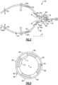
- FIG. 2 shows a sectioned view of the combustion system 38 taken along a radial plane that includes the engine axis A (superimposed).
- the combustion system 38 includes a combustion chamber 40 in the combustor section 26 for introducing hydrogen and combustion gas (e.g., air in the examples herein).
- the combustion chamber 40 is annularly disposed about the engine axis, i.e., chamber 40 is an annulus around the axis A.
- the combustion chamber 40 has first and second axial ends 40a/40b and radially inner and outer walls 40c/40d. Radially "inner” and “outer” as used herein indicate radial proximity to the engine axis A.
- the injector ring 42 disposed about the engine axis A (e.g., co-axial with axis A) at the first axial end 40a that is connected to the fuel system 32 (hydrogen source) and the compressor section 24 for introducing a hydrogen and air mixture into the combustion chamber 40.
- the injector ring 42 includes an injector body 50 that defines a hydrogen manifold cavity 52 and hydrogen feed conduits 54 that extend off of the hydrogen manifold cavity 52 and open into a mixing region 56 at an axial end of the injector ring 42.
- the hydrogen manifold cavity 52 includes an open-cell metallic foam 58.
- the open-cell metallic foam 58 is formed of an alloy that has low susceptibility to hydrogen embrittlement, such as but not limited to, stainless steel or nickel alloy, and which is corrosion resistant and temperature resistant at the expected operating conditions.
- the foam 58 serves as a flame arrestor, allowing feed flow of hydrogen but facilitating the prevention of flame propagation back (flashback) through the injector ring 42. In general, flashback is prevented when the gas injection speed is higher than the local flame propagation speed.
- Figure 4 illustrates an axial view of a representative example arc section of the injector ring 42.
- the injector ring 42 includes radially inner and outer annular band sections 42a/42b and a radially intermediate annular band section 42c between the radially inner and outer annular band sections 42a/42b.
- the hydrogen feed conduits 54 are within the intermediate annular band section 42c and are tangentially-sloped with respect to the engine axis A.
- tangential slope refers to an orientation that (a) forms an oblique angle with the engine axis A and (b) lies in a plane that is (i) non-intersecting with the engine axis A and (ii) is substantially tangent to the circumference at the radial location where the conduit 54 opens to the mixing region 56.
- a tangential slope is in either a clockwise or counter-clockwise direction with respect to the engine axis A (looking aft).
- the slope is taken with respect to the central axis of the passage at the plane of its exit.
- a “conduit” as used herein is defined by one or more structures that together convey a fluid from one point to another.
- a conduit conveying fluid from point A to point B may include one of, or a combination of: a tube, an aperture defined through a part of an engine, a filter, a pump, and so on, depending on the application and context as would be understood by a person of ordinary skill in the art reading the present disclosure.
- the radially inner and outer annular band sections 42a/42b include gas (air) feed conduits 60 that also open into the mixing region 56.
- gas feed conduits 60 are radially and tangentially sloped.
- the term "radial slope" refers to an orientation that has a radial angle component with respect to the engine axis A. For instance, a radial slope is either in a radially inwardly or outwardly direction with respect to the engine axis A (looking aft).
- the gas feed conduits 60 in the radially inner annular band 42a are radially outwardly sloped, and the gas feed conduits 60 in the radially outer annular band are radially inwardly sloped. Additionally, the gas feed conduits 60 and the hydrogen feed conduits 54 are tangentially sloped in a common clockwise or common counter-clockwise direction ( Figure 4 is clockwise, as the figure view is axial looking forward).
- the orientations of the feed conduits 54/60 facilitate good mixing of the hydrogen and air, as well as 3D circulation in the combustion chamber 40.
- the tangential slopes of the feed conduits 54/60 swirl the flows of hydrogen and air about the engine axis A.
- the radial slope of the gas feed conduits 60 directs flow of air across the face of the intermediate annular band section 42c, thereby facilitating mixing with the hydrogen and directing the mixture downstream into the combustion chamber 40.
- the combustion chamber 40 may also include cooling jets 62 for introducing additional air for combustion and cooling the walls of the chamber 40, as well as downstream dilution jets 64 for further controlling stability and radial flame profile.
- the dilution jets 64 may also be tangentially-sloped for further swirling effect.
- the dilution jets 64 are tangentially sloped in the opposite direction (clockwise or counter-clockwise) of the tangential slopes of the feed passages 54/60.
- Such a configuration facilitates producing a counter-swirl to the bulk of the flow in the combustion chamber 40 from the injector ring 42, for more rapid uniform circumferential mixing.
- the injector ring 42 may introduce approximately 15% to 25% of the air for combustion into the combustion chamber 40, and the remainder of the air may be provided by the cooling jets 62 and dilution holes 65.
- This combustion chamber 40 may also work for lean-burn combustion system. For example, approximately 60% to 80% of the combustion air can be introduced through the injector ring 42 into the combustion chamber 40. The remainder of the air can be used for the combustor exit temperature profile trimming through dilution or profile trimming jets 64.
- Figure 5 illustrates an example configuration of the combustion system 38 for fuel staging.
- the injector ring 42 is comprised of arc sections 66/68 that serve, respectively, as pilot sections and main sections.
- the sections 66/68 circumferentially alternate such that each of the pilot sections 66 is circumferentially between two of the main sections 68 and each of the main sections 68 is circumferentially between two of the pilot sections 66.
- the pilot sections 66 each have first arc length (L1) about the axis A
- the main sections 68 each have a second arc length (L2) about the axis A
- the first arc length L1 is smaller than the second arc length L2.
- Such a configuration may also facilitate control of power output, widening of the flame stability envelope, and thermoacoustic stability.
- the pilot sections 66 introduce a first percentage of the hydrogen and air mixture into the combustion chamber 40, and the main sections 68 introduce a second percentage of the hydrogen and air mixture into the combustion chamber.
- the pilot sections 66 are used for engine starting, flame stability, and power level controls.
- the percentage of the hydrogen and air mixture provided by the pilot sections 66 versus the percentage provided by the main sections 68 may be adjusted based on engine performance.
- the stoichiometric ratios of the hydrogen and air in the mixtures provided by the sections 66/68 may also be adjusted for further control over engine performance.
- an engine controller may control the percentage and ratios in accordance with a control schedule, such as a lookup table.
- the fuel system 32 may include valves, flow meters, and other known flow control devices that are configured to be operated by the controller in response to the control schedule to control flow of hydrogen and air.
- a gas turbine engine 20 includes an annular combustion chamber 40 disposed about an axis A, first and second axial ends 40a/40b, and radially inner and outer walls 40c/40d, and an injector ring 42 disposed about the axis A at the first axial end 40a for introducing a hydrogen and gas mixture into the combustion chamber 40.
- the injector ring 42 includes a hydrogen manifold cavity 52 and hydrogen feed conduits 54 that extend off of the hydrogen manifold cavity 52 and open into a mixing region 56 at an axial end of the injector ring 42.
- the hydrogen manifold cavity 52 includes an open-cell metallic foam 58.
- the injector ring 42 includes radially inner and outer annular band sections 42a/42b, a radially intermediate annular band section 42c between the radially inner annular band section 42a and the radially outer annular band section 42b, and the hydrogen feed conduits 54 are within the intermediate annular band section 42c.
- the hydrogen feed conduits 54 are tangentially-sloped.
- the radially inner and outer annular band sections 42a/42b include gas feed conduits 60 that open into the mixing region 56.
- the gas feed passages 60 are radially and tangentially sloped.
- the gas feed passages 60 in the radially inner annular band section 42a are radially outwardly sloped, and the gas feed passages 60 in the radially outer annular band section 42b are radially inwardly sloped.
- gas feed passages 60 and the hydrogen feed passages 54 are tangentially sloped in a common clockwise or common counter-clockwise direction.
- the injector ring 42 includes pilot injector arc sections 66 for introducing a first percentage of the hydrogen and gas mixture into the combustion chamber 40 and main injector arc segments 68 for introducing a second percentage of the hydrogen and gas mixture into the combustion chamber 40.
- pilot injector arc segments 66 and the main injector arc segments 68 circumferentially alternate such that each of the pilot injector arc segments 66 is circumferentially between two of the main injector arc segments 68 and each of the main injector arc segments 68 is circumferentially between two of the pilot injector arc segments 66.
- An example gas turbine engine includes a combustor section 26 that has a combustion chamber 40 disposed about an axis A, first and second axial ends 40a/40b, and radially inner and outer walls 40c/40d, hydrogen source 32, and an injector ring 42 disposed about the axis A at the first axial end 40a and configured to introduce a hydrogen and gas mixture into the combustion chamber 40.
- the injector ring 42 includes a hydrogen manifold cavity 52 and hydrogen feed passages 54 that extend off of the hydrogen manifold cavity 52 and open into a mixing region 56 at an axial end of the injector ring 42, an open-cell metallic foam 58 disposed in the hydrogen manifold cavity 52, radially inner and outer annular band sections 42a/42b, a radially intermediate annular band section 42c between the radially inner annular band section 42a and the radially outer annular band section 42b, the hydrogen feed passages 54 being within the intermediate annular band section 42c, and gas feed passages 60 in the radially inner and outer annular band sections 42a/42b that open into the mixing region 56.
Landscapes
- Engineering & Computer Science (AREA)
- Chemical & Material Sciences (AREA)
- Combustion & Propulsion (AREA)
- Mechanical Engineering (AREA)
- General Engineering & Computer Science (AREA)
- Output Control And Ontrol Of Special Type Engine (AREA)
- Pre-Mixing And Non-Premixing Gas Burner (AREA)
Applications Claiming Priority (1)
| Application Number | Priority Date | Filing Date | Title |
|---|---|---|---|
| US202363482860P | 2023-02-02 | 2023-02-02 |
Publications (2)
| Publication Number | Publication Date |
|---|---|
| EP4411234A1 true EP4411234A1 (fr) | 2024-08-07 |
| EP4411234B1 EP4411234B1 (fr) | 2025-09-03 |
Family
ID=89767398
Family Applications (1)
| Application Number | Title | Priority Date | Filing Date |
|---|---|---|---|
| EP24154144.0A Active EP4411234B1 (fr) | 2023-02-02 | 2024-01-26 | Moteur à turbine à gaz à hydrogène avec anneau d'injecteur |
Country Status (3)
| Country | Link |
|---|---|
| US (1) | US20240263783A1 (fr) |
| EP (1) | EP4411234B1 (fr) |
| CA (1) | CA3227882A1 (fr) |
Families Citing this family (2)
| Publication number | Priority date | Publication date | Assignee | Title |
|---|---|---|---|---|
| EP4411235B1 (fr) * | 2023-02-02 | 2025-08-27 | Pratt & Whitney Canada Corp. | Moteur à turbine à gaz à hydrogène avec anneau d'injecteur et alimentation étagée de carburant |
| EP4603689A1 (fr) * | 2024-02-19 | 2025-08-20 | Rolls-Royce plc | Aéronef comprenant un moteur à turbine à gaz ayant des injecteurs de carburant primaire et secondaire |
Citations (5)
| Publication number | Priority date | Publication date | Assignee | Title |
|---|---|---|---|---|
| EP2853818A1 (fr) * | 2013-09-26 | 2015-04-01 | Siemens Aktiengesellschaft | Brûleur destiné à un système de combustion avec un élément de prémélange et élément de refroidissement, système de combustion doté d'un brûleur et utilisation du système de combustion |
| WO2018144008A1 (fr) * | 2017-02-03 | 2018-08-09 | Siemens Aktiengesellschaft | Chambre de combustion avec pré-mélangeur en treillis tridimensionnel |
| US20220099299A1 (en) * | 2020-09-30 | 2022-03-31 | Rolls-Royce Plc | Fuel injection |
| WO2022202103A1 (fr) * | 2021-03-25 | 2022-09-29 | 株式会社Ihi | Dispositif de combustion et système de turbine à gaz |
| WO2022214384A1 (fr) * | 2021-04-06 | 2022-10-13 | Siemens Energy Global GmbH & Co. KG | Chambre de combustion pour turbine à gaz |
Family Cites Families (9)
| Publication number | Priority date | Publication date | Assignee | Title |
|---|---|---|---|---|
| US4996838A (en) * | 1988-10-27 | 1991-03-05 | Sol-3 Resources, Inc. | Annular vortex slinger combustor |
| US7506511B2 (en) * | 2003-12-23 | 2009-03-24 | Honeywell International Inc. | Reduced exhaust emissions gas turbine engine combustor |
| US20090090110A1 (en) * | 2007-10-04 | 2009-04-09 | Honeywell International, Inc. | Faceted dome assemblies for gas turbine engine combustors |
| US9366187B2 (en) * | 2013-03-12 | 2016-06-14 | Pratt & Whitney Canada Corp. | Slinger combustor |
| EP2930430A1 (fr) * | 2014-04-07 | 2015-10-14 | Siemens Aktiengesellschaft | Bec de brûleur et brûleur d'une turbine à gaz |
| KR102268594B1 (ko) * | 2015-03-18 | 2021-06-23 | 한화에어로스페이스 주식회사 | 연료 분사 시스템 및 그 제어 방법 |
| US10578021B2 (en) * | 2015-06-26 | 2020-03-03 | Delavan Inc | Combustion systems |
| CN115899765B (zh) * | 2021-09-30 | 2026-03-31 | 通用电气公司 | 用于降低排放的带有旋流轮叶的环形燃烧器稀释 |
| US11747018B2 (en) * | 2022-01-05 | 2023-09-05 | General Electric Company | Combustor with dilution openings |
-
2024
- 2024-01-26 EP EP24154144.0A patent/EP4411234B1/fr active Active
- 2024-01-30 US US18/426,506 patent/US20240263783A1/en active Pending
- 2024-02-01 CA CA3227882A patent/CA3227882A1/fr active Pending
Patent Citations (5)
| Publication number | Priority date | Publication date | Assignee | Title |
|---|---|---|---|---|
| EP2853818A1 (fr) * | 2013-09-26 | 2015-04-01 | Siemens Aktiengesellschaft | Brûleur destiné à un système de combustion avec un élément de prémélange et élément de refroidissement, système de combustion doté d'un brûleur et utilisation du système de combustion |
| WO2018144008A1 (fr) * | 2017-02-03 | 2018-08-09 | Siemens Aktiengesellschaft | Chambre de combustion avec pré-mélangeur en treillis tridimensionnel |
| US20220099299A1 (en) * | 2020-09-30 | 2022-03-31 | Rolls-Royce Plc | Fuel injection |
| WO2022202103A1 (fr) * | 2021-03-25 | 2022-09-29 | 株式会社Ihi | Dispositif de combustion et système de turbine à gaz |
| WO2022214384A1 (fr) * | 2021-04-06 | 2022-10-13 | Siemens Energy Global GmbH & Co. KG | Chambre de combustion pour turbine à gaz |
Also Published As
| Publication number | Publication date |
|---|---|
| CA3227882A1 (fr) | 2025-04-17 |
| US20240263783A1 (en) | 2024-08-08 |
| EP4411234B1 (fr) | 2025-09-03 |
Similar Documents
| Publication | Publication Date | Title |
|---|---|---|
| US10465909B2 (en) | Mini mixing fuel nozzle assembly with mixing sleeve | |
| US7966821B2 (en) | Reduced exhaust emissions gas turbine engine combustor | |
| US12298008B2 (en) | Fuel system with radially arranged injectors for hydrogen-driven gas turbine engine | |
| AU2019271909B2 (en) | Premixed fuel nozzle | |
| EP4411234A1 (fr) | Moteur à turbine à gaz à hydrogène avec anneau d'injecteur | |
| US11841141B2 (en) | Reverse flow combustor | |
| US11592182B1 (en) | Swirler ferrule plate having pressure drop purge passages | |
| US20230213194A1 (en) | Turbine engine fuel premixer | |
| US12038176B2 (en) | Coupling a fuel nozzle purge flow directly to a swirler | |
| US11994295B2 (en) | Multi pressure drop swirler ferrule plate | |
| US20220373182A1 (en) | Pilot fuel nozzle assembly with vented venturi | |
| EP4411241A1 (fr) | Système de carburant avec injecteurs pilotes et injecteurs principaux pour moteur à turbine à gaz à hydrogène | |
| EP4411243A1 (fr) | Injecteur avec carénage et passage annulaire pour moteur à turbine à gaz entraîné par hydrogène | |
| EP4411235B1 (fr) | Moteur à turbine à gaz à hydrogène avec anneau d'injecteur et alimentation étagée de carburant | |
| EP4411226A1 (fr) | Passage d'air central avec distributeur de carburant radial | |
| EP4411237B1 (fr) | Injecteur avec disque pour moteur à turbine à gaz à hydrogène | |
| US20250257874A1 (en) | Pilot fuel nozzle assembly with multi-angled venturi | |
| US12196422B2 (en) | Combustor with secondary fuel nozzle in dilution fence |
Legal Events
| Date | Code | Title | Description |
|---|---|---|---|
| PUAI | Public reference made under article 153(3) epc to a published international application that has entered the european phase |
Free format text: ORIGINAL CODE: 0009012 |
|
| STAA | Information on the status of an ep patent application or granted ep patent |
Free format text: STATUS: THE APPLICATION HAS BEEN PUBLISHED |
|
| AK | Designated contracting states |
Kind code of ref document: A1 Designated state(s): AL AT BE BG CH CY CZ DE DK EE ES FI FR GB GR HR HU IE IS IT LI LT LU LV MC ME MK MT NL NO PL PT RO RS SE SI SK SM TR |
|
| STAA | Information on the status of an ep patent application or granted ep patent |
Free format text: STATUS: REQUEST FOR EXAMINATION WAS MADE |
|
| 17P | Request for examination filed |
Effective date: 20250204 |
|
| GRAP | Despatch of communication of intention to grant a patent |
Free format text: ORIGINAL CODE: EPIDOSNIGR1 |
|
| STAA | Information on the status of an ep patent application or granted ep patent |
Free format text: STATUS: GRANT OF PATENT IS INTENDED |
|
| INTG | Intention to grant announced |
Effective date: 20250325 |
|
| RIN1 | Information on inventor provided before grant (corrected) |
Inventor name: HU, TIN CHEUNG JOHN |
|
| GRAS | Grant fee paid |
Free format text: ORIGINAL CODE: EPIDOSNIGR3 |
|
| GRAA | (expected) grant |
Free format text: ORIGINAL CODE: 0009210 |
|
| STAA | Information on the status of an ep patent application or granted ep patent |
Free format text: STATUS: THE PATENT HAS BEEN GRANTED |
|
| AK | Designated contracting states |
Kind code of ref document: B1 Designated state(s): AL AT BE BG CH CY CZ DE DK EE ES FI FR GB GR HR HU IE IS IT LI LT LU LV MC ME MK MT NL NO PL PT RO RS SE SI SK SM TR |
|
| REG | Reference to a national code |
Ref country code: CH Ref legal event code: EP |
|
| REG | Reference to a national code |
Ref country code: DE Ref legal event code: R096 Ref document number: 602024000547 Country of ref document: DE |
|
| REG | Reference to a national code |
Ref country code: IE Ref legal event code: FG4D |
|
| REG | Reference to a national code |
Ref country code: NL Ref legal event code: MP Effective date: 20250903 |
|
| PG25 | Lapsed in a contracting state [announced via postgrant information from national office to epo] |
Ref country code: NO Free format text: LAPSE BECAUSE OF FAILURE TO SUBMIT A TRANSLATION OF THE DESCRIPTION OR TO PAY THE FEE WITHIN THE PRESCRIBED TIME-LIMIT Effective date: 20251203 |
|
| REG | Reference to a national code |
Ref country code: LT Ref legal event code: MG9D |
|
| PG25 | Lapsed in a contracting state [announced via postgrant information from national office to epo] |
Ref country code: FI Free format text: LAPSE BECAUSE OF FAILURE TO SUBMIT A TRANSLATION OF THE DESCRIPTION OR TO PAY THE FEE WITHIN THE PRESCRIBED TIME-LIMIT Effective date: 20250903 |
|
| PG25 | Lapsed in a contracting state [announced via postgrant information from national office to epo] |
Ref country code: HR Free format text: LAPSE BECAUSE OF FAILURE TO SUBMIT A TRANSLATION OF THE DESCRIPTION OR TO PAY THE FEE WITHIN THE PRESCRIBED TIME-LIMIT Effective date: 20250903 |
|
| PGFP | Annual fee paid to national office [announced via postgrant information from national office to epo] |
Ref country code: FR Payment date: 20251217 Year of fee payment: 3 |
|
| PG25 | Lapsed in a contracting state [announced via postgrant information from national office to epo] |
Ref country code: GR Free format text: LAPSE BECAUSE OF FAILURE TO SUBMIT A TRANSLATION OF THE DESCRIPTION OR TO PAY THE FEE WITHIN THE PRESCRIBED TIME-LIMIT Effective date: 20251204 |
|
| PG25 | Lapsed in a contracting state [announced via postgrant information from national office to epo] |
Ref country code: SE Free format text: LAPSE BECAUSE OF FAILURE TO SUBMIT A TRANSLATION OF THE DESCRIPTION OR TO PAY THE FEE WITHIN THE PRESCRIBED TIME-LIMIT Effective date: 20250903 |
|
| PG25 | Lapsed in a contracting state [announced via postgrant information from national office to epo] |
Ref country code: LV Free format text: LAPSE BECAUSE OF FAILURE TO SUBMIT A TRANSLATION OF THE DESCRIPTION OR TO PAY THE FEE WITHIN THE PRESCRIBED TIME-LIMIT Effective date: 20250903 |
|
| PG25 | Lapsed in a contracting state [announced via postgrant information from national office to epo] |
Ref country code: PL Free format text: LAPSE BECAUSE OF FAILURE TO SUBMIT A TRANSLATION OF THE DESCRIPTION OR TO PAY THE FEE WITHIN THE PRESCRIBED TIME-LIMIT Effective date: 20250903 Ref country code: BG Free format text: LAPSE BECAUSE OF FAILURE TO SUBMIT A TRANSLATION OF THE DESCRIPTION OR TO PAY THE FEE WITHIN THE PRESCRIBED TIME-LIMIT Effective date: 20250903 |
|
| PG25 | Lapsed in a contracting state [announced via postgrant information from national office to epo] |
Ref country code: RS Free format text: LAPSE BECAUSE OF FAILURE TO SUBMIT A TRANSLATION OF THE DESCRIPTION OR TO PAY THE FEE WITHIN THE PRESCRIBED TIME-LIMIT Effective date: 20251203 |
|
| PG25 | Lapsed in a contracting state [announced via postgrant information from national office to epo] |
Ref country code: ES Free format text: LAPSE BECAUSE OF FAILURE TO SUBMIT A TRANSLATION OF THE DESCRIPTION OR TO PAY THE FEE WITHIN THE PRESCRIBED TIME-LIMIT Effective date: 20250903 |
|
| REG | Reference to a national code |
Ref country code: AT Ref legal event code: MK05 Ref document number: 1833444 Country of ref document: AT Kind code of ref document: T Effective date: 20250903 |
|
| PG25 | Lapsed in a contracting state [announced via postgrant information from national office to epo] |
Ref country code: NL Free format text: LAPSE BECAUSE OF FAILURE TO SUBMIT A TRANSLATION OF THE DESCRIPTION OR TO PAY THE FEE WITHIN THE PRESCRIBED TIME-LIMIT Effective date: 20250903 |
|
| PG25 | Lapsed in a contracting state [announced via postgrant information from national office to epo] |
Ref country code: SM Free format text: LAPSE BECAUSE OF FAILURE TO SUBMIT A TRANSLATION OF THE DESCRIPTION OR TO PAY THE FEE WITHIN THE PRESCRIBED TIME-LIMIT Effective date: 20250903 |
|
| PGFP | Annual fee paid to national office [announced via postgrant information from national office to epo] |
Ref country code: DE Payment date: 20251217 Year of fee payment: 3 |
|
| PG25 | Lapsed in a contracting state [announced via postgrant information from national office to epo] |
Ref country code: AT Free format text: LAPSE BECAUSE OF FAILURE TO SUBMIT A TRANSLATION OF THE DESCRIPTION OR TO PAY THE FEE WITHIN THE PRESCRIBED TIME-LIMIT Effective date: 20250903 |
|
| PG25 | Lapsed in a contracting state [announced via postgrant information from national office to epo] |
Ref country code: IT Free format text: LAPSE BECAUSE OF FAILURE TO SUBMIT A TRANSLATION OF THE DESCRIPTION OR TO PAY THE FEE WITHIN THE PRESCRIBED TIME-LIMIT Effective date: 20250903 |
|
| PG25 | Lapsed in a contracting state [announced via postgrant information from national office to epo] |
Ref country code: IS Free format text: LAPSE BECAUSE OF FAILURE TO SUBMIT A TRANSLATION OF THE DESCRIPTION OR TO PAY THE FEE WITHIN THE PRESCRIBED TIME-LIMIT Effective date: 20260103 |
|
| PG25 | Lapsed in a contracting state [announced via postgrant information from national office to epo] |
Ref country code: CZ Free format text: LAPSE BECAUSE OF FAILURE TO SUBMIT A TRANSLATION OF THE DESCRIPTION OR TO PAY THE FEE WITHIN THE PRESCRIBED TIME-LIMIT Effective date: 20250903 Ref country code: PT Free format text: LAPSE BECAUSE OF FAILURE TO SUBMIT A TRANSLATION OF THE DESCRIPTION OR TO PAY THE FEE WITHIN THE PRESCRIBED TIME-LIMIT Effective date: 20260105 |
|
| PG25 | Lapsed in a contracting state [announced via postgrant information from national office to epo] |
Ref country code: SK Free format text: LAPSE BECAUSE OF FAILURE TO SUBMIT A TRANSLATION OF THE DESCRIPTION OR TO PAY THE FEE WITHIN THE PRESCRIBED TIME-LIMIT Effective date: 20250903 Ref country code: EE Free format text: LAPSE BECAUSE OF FAILURE TO SUBMIT A TRANSLATION OF THE DESCRIPTION OR TO PAY THE FEE WITHIN THE PRESCRIBED TIME-LIMIT Effective date: 20250903 |