WO2022202103A1 - Dispositif de combustion et système de turbine à gaz - Google Patents
Dispositif de combustion et système de turbine à gaz Download PDFInfo
- Publication number
- WO2022202103A1 WO2022202103A1 PCT/JP2022/008006 JP2022008006W WO2022202103A1 WO 2022202103 A1 WO2022202103 A1 WO 2022202103A1 JP 2022008006 W JP2022008006 W JP 2022008006W WO 2022202103 A1 WO2022202103 A1 WO 2022202103A1
- Authority
- WO
- WIPO (PCT)
- Prior art keywords
- air
- hydrogen
- flow path
- combustion chamber
- channel
- Prior art date
- Legal status (The legal status is an assumption and is not a legal conclusion. Google has not performed a legal analysis and makes no representation as to the accuracy of the status listed.)
- Ceased
Links
Images



Classifications
-
- F—MECHANICAL ENGINEERING; LIGHTING; HEATING; WEAPONS; BLASTING
- F23—COMBUSTION APPARATUS; COMBUSTION PROCESSES
- F23D—BURNERS
- F23D14/00—Burners for combustion of a gas, e.g. of a gas stored under pressure as a liquid
- F23D14/20—Non-premix gas burners, i.e. in which gaseous fuel is mixed with combustion air on arrival at the combustion zone
- F23D14/22—Non-premix gas burners, i.e. in which gaseous fuel is mixed with combustion air on arrival at the combustion zone with separate air and gas feed ducts, e.g. with ducts running parallel or crossing each other
-
- F—MECHANICAL ENGINEERING; LIGHTING; HEATING; WEAPONS; BLASTING
- F23—COMBUSTION APPARATUS; COMBUSTION PROCESSES
- F23D—BURNERS
- F23D14/00—Burners for combustion of a gas, e.g. of a gas stored under pressure as a liquid
- F23D14/20—Non-premix gas burners, i.e. in which gaseous fuel is mixed with combustion air on arrival at the combustion zone
- F23D14/22—Non-premix gas burners, i.e. in which gaseous fuel is mixed with combustion air on arrival at the combustion zone with separate air and gas feed ducts, e.g. with ducts running parallel or crossing each other
- F23D14/24—Non-premix gas burners, i.e. in which gaseous fuel is mixed with combustion air on arrival at the combustion zone with separate air and gas feed ducts, e.g. with ducts running parallel or crossing each other at least one of the fluids being submitted to a swirling motion
-
- F—MECHANICAL ENGINEERING; LIGHTING; HEATING; WEAPONS; BLASTING
- F23—COMBUSTION APPARATUS; COMBUSTION PROCESSES
- F23R—GENERATING COMBUSTION PRODUCTS OF HIGH PRESSURE OR HIGH VELOCITY, e.g. GAS-TURBINE COMBUSTION CHAMBERS
- F23R3/00—Continuous combustion chambers using liquid or gaseous fuel
- F23R3/02—Continuous combustion chambers using liquid or gaseous fuel characterised by the air-flow or gas-flow configuration
- F23R3/04—Air inlet arrangements
- F23R3/10—Air inlet arrangements for primary air
-
- F—MECHANICAL ENGINEERING; LIGHTING; HEATING; WEAPONS; BLASTING
- F23—COMBUSTION APPARATUS; COMBUSTION PROCESSES
- F23R—GENERATING COMBUSTION PRODUCTS OF HIGH PRESSURE OR HIGH VELOCITY, e.g. GAS-TURBINE COMBUSTION CHAMBERS
- F23R3/00—Continuous combustion chambers using liquid or gaseous fuel
- F23R3/28—Continuous combustion chambers using liquid or gaseous fuel characterised by the fuel supply
Definitions
- a gas turbine system that obtains power by burning fuel in a combustor is used.
- a gas turbine system for example, as disclosed in Patent Document 1, there is a system that uses hydrogen as a fuel. Using hydrogen as a fuel reduces carbon dioxide emissions.
- the combustion speed of hydrogen is much faster than that of other fuels such as natural gas. Therefore, similar to the case where natural gas or the like is used as fuel, if fuel and air are premixed and supplied from the burner to the combustion chamber of the combustor, flashback (that is, burner A phenomenon in which the flame flows back inside) is likely to occur. Also, the temperature of the flame formed by burning hydrogen is higher than the temperature of the flame formed by burning other fuels. Therefore, the burner is easily damaged by the flame. Thus, there is a great need to protect the burner from flames.
- An object of the present disclosure is to provide a combustion device and gas turbine system that can protect the burner from flames.
- the combustion device of the present disclosure includes a combustion chamber, a hydrogen flow path having a hydrogen injection port facing the combustion chamber, a first air flow path having a first air injection port facing the combustion chamber, and and a plurality of flow passage groups each having a second air flow passage extending in a direction intersecting with the first air flow passage and having a second air injection port facing the combustion chamber.
- a plurality of hydrogen channels may be provided in at least one channel group.
- the hydrogen flow path is aligned with the first air flow path and the second air flow path in a direction crossing the extending direction of the first air flow path and the extending direction of the second air flow path. It may be placed between roads.
- the hydrogen flow channel is arranged parallel to one of the first air flow channel and the second air flow channel in a direction in which one of the flow channels is inclined with respect to the axial direction of the combustion chamber. may be set.
- a burner plate that closes the end of the combustion chamber may be provided, and a plurality of flow path groups may be formed in the burner plate.
- a manifold communicating with a plurality of hydrogen channels may be formed on the burner plate.
- the gas turbine system of the present disclosure includes the above combustion device.
- the burner can be protected from flame.
- FIG. 1 is a schematic diagram showing the configuration of a gas turbine system according to an embodiment of the present disclosure.
- FIG. 2 is a view of a burner plate according to an embodiment of the present disclosure as seen from the combustion chamber side.
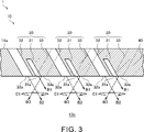
- FIG. 3 is a cross-sectional view along the A2-A2 cross section in FIG.
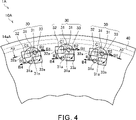
- FIG. 4 is a view of the burner plate according to the first modification as viewed from the combustion chamber side.
- FIG. 5 is a cross-sectional view along the A3-A3 cross section in FIG.
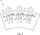
- FIG. 6 is a view of the burner plate according to the second modification as viewed from the combustion chamber side.
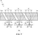
- 7 is a cross-sectional view taken along the line A4-A4 in FIG. 6.
- FIG. 1 is a schematic diagram showing the configuration of a gas turbine system 1 according to this embodiment.
- the gas turbine system 1 includes a supercharger 11 , a generator 12 , a combustor 13 , a burner 14 , a hydrogen tank 15 and a flow control valve 16 .
- the combustor 13, the burner 14, the hydrogen tank 15, and the flow control valve 16 are included in the combustion device 10.
- the supercharger 11 has a compressor 11a and a turbine 11b. Compressor 11a and turbine 11b rotate as a unit. Compressor 11a and turbine 11b are connected by a shaft.
- the compressor 11 a is provided in an intake passage 21 connected to the combustor 13 . Air supplied to the combustor 13 flows through the intake passage 21 . An intake port (not shown) through which air is taken in from the outside is provided at the upstream end of the intake passage 21 . Air taken in from the intake port passes through the compressor 11 a and is sent to the combustor 13 . The compressor 11a compresses air and discharges it downstream.
- the turbine 11 b is provided in an exhaust flow path 22 connected to the combustor 13 . Exhaust gas discharged from the combustor 13 flows through the exhaust flow path 22 . An exhaust port (not shown) through which the exhaust gas is discharged to the outside is provided at the downstream end of the exhaust passage 22 . Exhaust gas discharged from the combustor 13 passes through the turbine 11b and is sent to the exhaust port. The turbine 11b generates rotational power by being rotated by the exhaust gas.
- the generator 12 is connected to the turbocharger 11.
- the generator 12 generates power using the rotational power generated by the supercharger 11 .
- the combustor 13 has a casing 13a, a liner 13b, and a combustion chamber 13c.
- the casing 13a has a substantially cylindrical shape.
- a liner 13b is provided inside the casing 13a.
- the liner 13b has a substantially cylindrical shape.
- the liner 13b is arranged coaxially with the casing 13a.
- a combustion chamber 13c is formed inside the liner 13b. That is, the internal space of the liner 13b corresponds to the combustion chamber 13c.
- the combustion chamber 13c is a substantially cylindrical space.
- An exhaust passage 22 is connected to the combustion chamber 13c.
- hydrogen and air are supplied to the combustion chamber 13c.
- hydrogen is used as fuel and is combusted.
- Exhaust gas generated by combustion in the combustion chamber 13 c is discharged to the exhaust passage 22 .
- a space S is formed between the inner surface of the casing 13a and the outer surface of the liner 13b.
- An intake passage 21 is connected to the space S. Air is sent to the space S from the compressor 11 a through the intake passage 21 .
- An opening is formed at the end of the liner 13b (the left end in FIG. 1).
- a burner 14 is inserted through an opening at the end of the liner 13b.
- the burner 14 has a burner plate 14a and a plurality of hydrogen supply pipes 14b.
- the burner plate 14a closes the opening at the end of the liner 13b. That is, the burner plate 14a closes the end of the combustion chamber 13c.
- the burner plate 14a has a disk shape.
- the hydrogen supply pipe 14b is connected to the surface of the burner plate 14a opposite to the combustion chamber 13c side.
- the hydrogen supply pipe 14b penetrates the casing 13a and extends to the outside of the casing 13a. In FIG. 1, three hydrogen supply pipes 14b are shown. However, the number of hydrogen supply pipes 14b is not limited.
- a first air channel 32 and a second air channel 33) are formed.
- a hydrogen channel formed in the burner plate 14a communicates with the hydrogen supply pipe 14b. Hydrogen is sent to the hydrogen supply pipe 14b as will be described later. Hydrogen sent from the hydrogen supply pipe 14b to the burner plate 14a passes through the hydrogen flow path of the burner plate 14a and is injected into the combustion chamber 13c. As indicated by the dashed-dotted line arrow in FIG. 1, the air sent to the space S passes through the space S and then reaches the surface of the burner plate 14a on the side opposite to the side of the combustion chamber 13c. The air sent to the burner plate 14a is injected into the combustion chamber 13c through the air flow path of the burner plate 14a.
- the hydrogen tank 15 stores hydrogen.
- the hydrogen may be liquid or gas.
- the hydrogen tank 15 is connected to the flow control valve 16 via the flow path 23 .
- the flow control valve 16 is connected to each hydrogen supply pipe 14b of the burner 14 via the flow path 24.
- Hydrogen stored in the hydrogen tank 15 is supplied to the hydrogen supply pipe 14b via the flow path 23, the flow control valve 16 and the flow path 24.
- the flow control valve 16 controls (that is, adjusts) the flow rate of hydrogen supplied from the hydrogen tank 15 to the hydrogen supply pipe 14b. By adjusting the opening degree of the flow control valve 16, the amount of hydrogen supplied from the hydrogen tank 15 to the hydrogen supply pipe 14b is adjusted.
- the circumferential direction of the combustion chamber 13c is also simply referred to as the circumferential direction.
- the radial direction of the combustion chamber 13c is also simply referred to as the radial direction.
- the axial direction of the combustion chamber 13c is also simply referred to as the axial direction.
- FIG. 2 is a view of the burner plate 14a viewed from the combustion chamber 13c side (specifically, a view viewed from the arrow A1 direction in FIG. 1). Specifically, FIG. 2 shows a part of the outer peripheral side of the burner plate 14a.
- FIG. 3 is a cross-sectional view along the A2-A2 cross section in FIG.
- the burner plate 14a is formed with a plurality of flow channel groups 30 each having a hydrogen flow channel 31, a first air flow channel 32 and a second air flow channel 33.
- the plurality of flow path groups 30 are arranged side by side in the circumferential direction.
- the interval (that is, the circumferential separation distance) between adjacent flow path groups 30 is not limited to the examples in FIGS. 2 and 3 .
- the plurality of flow path groups 30 may be arranged side by side at equal intervals, or may be arranged side by side at uneven intervals.
- the arrangement of the plurality of flow channel groups 30 is not limited to this example, as will be described later.
- the hydrogen flow path 31 has a hydrogen injection port 31a facing the inside of the combustion chamber 13c.
- the hydrogen injection port 31a is provided on the surface of the burner plate 14a on the side of the combustion chamber 13c.
- a manifold 40 communicating with the plurality of hydrogen channels 31 is formed in the burner plate 14a.
- Manifold 40 extends in the circumferential direction.
- the manifold 40 is, for example, annular.
- the manifold 40 communicates with the hydrogen channels 31 of each channel group 30 .
- the manifold 40 is provided radially outside the plurality of flow path groups 30 .
- the arrangement of the manifold 40 is not limited to this example.
- the manifold 40 may be provided radially inside the plurality of flow path groups 30 .
- a plurality of hydrogen supply pipes 14b of the burner 14 are connected to the manifold 40. Hydrogen is supplied to the hydrogen flow paths 31 of each flow path group 30 from the plurality of hydrogen supply pipes 14 b through the manifold 40 . The hydrogen supplied to the hydrogen flow path 31 is injected from the hydrogen injection port 31a into the combustion chamber 13c.
- the hydrogen channel 31 is formed linearly.
- the hydrogen flow path 31 is inclined to one side in the circumferential direction (clockwise direction in FIG. 2) with respect to the combustion chamber side axial direction.
- the combustion chamber side axial direction is the direction facing the combustion chamber 13c among the axial directions of the combustion chamber 13c.
- Inclining in the circumferential direction with respect to the combustion chamber side axial direction means extending in the direction of the vector obtained by combining the vector in the combustion chamber side axial direction and the vector in the circumferential direction, or It means to lean forward. That is, the extending direction of the hydrogen flow path 31 is a direction inclined to one side in the circumferential direction with respect to the axial direction on the combustion chamber side.
- the injection direction of hydrogen injected from the hydrogen injection port 31a is a direction inclined to one side in the circumferential direction with respect to the combustion chamber side axial direction, as indicated by the arrow B1.
- the extending direction of the hydrogen flow path 31 is not limited to this example.
- the hydrogen flow path 31 may be bent or curved.
- the channel cross-sectional area of the hydrogen channel 31 is, for example, constant at each position in the extending direction of the hydrogen channel 31 .
- the channel cross-sectional area of the hydrogen channel 31 may not be constant at each position in the extending direction of the hydrogen channel 31 .
- the cross-sectional area of the hydrogen flow channel 31 is smaller at the hydrogen injection port 31a than at other portions, the injection speed of hydrogen injected from the hydrogen injection port 31a increases, and the mixing of hydrogen and air becomes difficult. Promoted.
- the first air flow path 32 has a first air injection port 32a facing the inside of the combustion chamber 13c.
- the first air injection port 32a is provided on the surface of the burner plate 14a on the side of the combustion chamber 13c.
- the first air channel 32 is provided on the other circumferential side (counterclockwise direction in FIG. 2) of the hydrogen channel 31 .
- the first air injection port 32a is provided on the other side in the circumferential direction with respect to the hydrogen injection port 31a.
- the positional relationship between the first air channel 32 and the hydrogen channel 31 is not limited to this example.
- the first air flow path 32 is formed linearly.
- the first air flow path 32 penetrates the burner plate 14a from the side of the combustion chamber 13c to the side opposite to the side of the combustion chamber 13c.
- a part of the air sent to the burner plate 14 a through the space S inside the combustor 13 is supplied to the first air flow path 32 .
- the air supplied to the first air flow path 32 is injected from the first air injection port 32a into the combustion chamber 13c.
- the first air flow path 32 is inclined to one side in the circumferential direction (clockwise direction in FIG. 2) with respect to the combustion chamber side axial direction. That is, the extending direction of the first air flow path 32 is a direction inclined to one side in the circumferential direction with respect to the axial direction on the combustion chamber side. Therefore, the injection direction of the air injected from the first air injection port 32a is inclined to one side in the circumferential direction with respect to the combustion chamber side axial direction, as indicated by the arrow B2.
- the extending direction of the first air flow path 32 is not limited to this example. Strictly speaking, the first air flow path 32 may be curved. That is, strictly speaking, the inclination angle of the first air flow path 32 with respect to the axial direction on the combustion chamber side may slightly differ at each position in the extending direction of the first air flow path 32 .
- the channel cross-sectional area of the first air channel 32 is, for example, constant at each position in the extending direction of the first air channel 32 .
- the channel cross-sectional area of the first air channel 32 may not be constant at each position in the extending direction of the first air channel 32 . If the flow passage cross-sectional area of the first air flow passage 32 is smaller at the first air injection port 32a than at other portions, the injection speed of the air injected from the first air injection port 32a increases, and hydrogen and air mixing is promoted.
- the second air flow path 33 has a second air injection port 33a facing the inside of the combustion chamber 13c.
- the second air injection port 33a is provided on the surface of the burner plate 14a on the side of the combustion chamber 13c.
- the second air channel 33 is provided radially inside the hydrogen channel 31 and the first air channel 32 .
- the second air injection port 33a is provided radially inside the hydrogen injection port 31a.
- the circumferential position of the second air injection port 33a is one side in the circumferential direction (clockwise direction in FIG. 2) of the circumferential position of the first air injection port 32a.
- the radial position of the second air injection port 33a is radially inside the radial position of the first air injection port 32a.
- the positional relationship between the second air flow path 33 and the hydrogen flow path 31 and the first air flow path 32 is not limited to this example.
- the second air flow path 33 is formed linearly.
- the second air flow path 33 penetrates the burner plate 14a from the side of the combustion chamber 13c to the side opposite to the side of the combustion chamber 13c. A part of the air sent to the burner plate 14 a through the space S inside the combustor 13 is supplied to the second air flow path 33 .
- the air supplied to the second air flow path 33 is injected from the second air injection port 33a into the combustion chamber 13c.
- the second air flow path 33 is inclined to the other side in the circumferential direction (counterclockwise direction in FIG. 2) with respect to the combustion chamber side axial direction. That is, the extending direction of the second air flow path 33 is a direction inclined to the other side in the circumferential direction with respect to the axial direction on the combustion chamber side. Therefore, the injection direction of the air injected from the second air injection port 33a is inclined to the other side in the circumferential direction with respect to the combustion chamber side axial direction, as indicated by the arrow B3.
- the extension direction of the second air flow path 33 is not limited to this example as long as it crosses the extension direction of the first air flow path 32 . Strictly speaking, the second air flow path 33 may be curved. That is, strictly speaking, the inclination angle of the second air flow path 33 with respect to the axial direction on the combustion chamber side may slightly differ at each position in the extending direction of the second air flow path 33 .
- the channel cross-sectional area of the second air channel 33 is, for example, constant at each position in the extending direction of the second air channel 33 .
- the channel cross-sectional area of the second air channel 33 may not be constant at each position in the extending direction of the second air channel 33 . If the flow passage cross-sectional area of the second air flow path 33 is smaller at the second air injection port 33a than at other portions, the injection speed of the air injected from the second air injection port 33a increases, and the hydrogen and air mixing is promoted.
- the second air flow path 33 extends in a direction intersecting with the first air flow path 32 . Therefore, the direction of air jetted from the second air jet port 33a intersects the jet direction of air jetted from the first air jet port 32a. Specifically, as the first air flow path 32 approaches the combustion chamber 13c, it approaches the second air injection port 33a in a direction orthogonal to the axial direction of the combustion chamber 13c. On the other hand, as the second air flow path 33 approaches the combustion chamber 13c, it approaches the first air injection port 32a in the direction orthogonal to the axial direction of the combustion chamber 13c.
- the air injected from the first air injection port 32a and the air injected from the second air injection port 33a interfere with each other, and as indicated by the arrow C1, the air around the central axis in the axial direction of the combustion chamber 13c turn to
- the hydrogen injected from the hydrogen injection port 31a is injected toward the swirling flow of air indicated by the arrow C1. Therefore, the hydrogen injected from the hydrogen injection port 31a is swirled and mixed with the air by the swirling flow of air indicated by the arrow C1.
- the swirling flow of air generated in the combustion chamber 13c causes the hydrogen injected from the hydrogen injection port 31a to be rapidly mixed with the air. Therefore, compared to the case where hydrogen and air are premixed and supplied to the combustion chamber 13c, the ignition position is on the inner side of the combustion chamber 13c. Therefore, flashback is suppressed. In addition, erosion of the burner 14 is suppressed. Therefore, the burner 14 can be protected from flames. Furthermore, the flame is held at the center of the swirling flow and stabilized by the swirling flow of air generated in the combustion chamber 13c. Also, by appropriately adjusting the amount of air supplied and lowering the temperature of the flame, the amount of NOx emissions can be reduced.
- a plurality of flow path groups 30 are formed in the burner plate 14a closing the end of the combustion chamber 13c. Therefore, the plurality of flow path groups 30 can be easily formed by integrally molding the burner plate 14a by a metal lamination technique or the like.
- integrally molding the burner plate 14a in this manner the structure of the burner 14 is simplified and the burner 14 is made smaller than in the case where the member forming the plurality of flow path groups 30 is separate from the burner plate 14a. and the manufacturing cost of the burner 14 is reduced.
- leakage of hydrogen from the joint portion of the member is suppressed.
- the occurrence of cracks at the joint due to thermal stress is suppressed.
- the burner plate 14a is formed with a manifold 40 that communicates with the plurality of hydrogen flow paths 31. Therefore, the manifold 40 can be easily formed by integrally molding the burner plate 14a by a metal lamination technique or the like.
- integrally molding the burner plate 14a in this manner the structure of the burner 14 is simplified, the burner 14 is miniaturized, and the burner 14 is reduced in size, compared with the case where the member forming the manifold 40 is separate from the burner plate 14a. 14 manufacturing costs are reduced.
- leakage of hydrogen from the joint portion of the member is suppressed.
- the occurrence of cracks at the joint due to thermal stress is suppressed.
- each part obtained by dividing the burner plate 14a may be integrally molded by a metal lamination technique or the like, and the obtained members may be assembled. Also in this case, the manufacturing cost of the burner 14 is reduced, hydrogen leakage from the joints of the members is suppressed, and cracks at the joints due to thermal stress are suppressed.
- FIG. 1 the configuration other than the burner plate is the same as the gas turbine system 1 described above, so description thereof will be omitted.
- FIG. 4 is a view of the burner plate 14aA according to the first modified example viewed from the combustion chamber 13c side. Specifically, FIG. 4 shows a part of the outer peripheral side of the burner plate 14aA.
- FIG. 5 is a cross-sectional view along the A3-A3 cross section in FIG. As shown in FIGS. 4 and 5, a combustion device 10A of a gas turbine system 1A according to the first modification includes a burner plate 14aA.
- the burner plate 14aA differs from the burner plate 14a described above in that each channel group 30 is provided with a plurality of hydrogen channels 31 .
- each channel group 30 formed in the burner plate 14aA has two hydrogen channels 31, a first air channel 32 and a second air channel 33.
- the first air channel 32 is positioned radially outward with respect to the second air channel 33.
- the first air flow path 32 is inclined to one side in the circumferential direction (clockwise direction in FIG. 4) with respect to the combustion chamber side axial direction.
- the second air flow path 33 is inclined to the other side in the circumferential direction (counterclockwise direction in FIG. 4) with respect to the combustion chamber side axial direction.
- the circumferential position of the second air injection port 33a is one side in the circumferential direction of the circumferential position of the first air injection port 32a.
- the radial position of the second air injection port 33a is radially inside the radial position of the first air injection port 32a.
- Both of the two hydrogen flow paths 31 have hydrogen injection ports 31a facing the inside of the combustion chamber 13c. Both of the two hydrogen channels 31 communicate with the manifold 40 .
- one hydrogen flow channel 31 (top right hydrogen flow channel 31 in FIG. 4) is arranged on one side of the first air flow channel 32 in the circumferential direction (clockwise ), and is provided radially outward with respect to the second air flow path 33 .
- the hydrogen injection port 31a of one of the hydrogen flow paths 31 is provided on one side in the circumferential direction with respect to the first air injection port 32a and radially outwardly with respect to the second air injection port 33a.
- One hydrogen flow path 31 is inclined to one side in the circumferential direction (clockwise direction in FIG. 4) with respect to the combustion chamber side axial direction. That is, the extending direction of one of the hydrogen flow paths 31 is a direction inclined to one side in the circumferential direction with respect to the axial direction on the combustion chamber side. Therefore, the injection direction of hydrogen injected from the hydrogen injection port 31a of one of the hydrogen flow passages 31 is the direction inclined to one side in the circumferential direction with respect to the axial direction on the combustion chamber side, as indicated by the arrow B1.
- the other hydrogen flow channel 31 (lower left hydrogen flow channel 31 in FIG. 4) is arranged on the other side of the second air flow channel 33 in the circumferential direction (counterclockwise in FIG. direction) and radially inward with respect to the first air flow path 32 .
- the hydrogen injection port 31a of the other hydrogen flow path 31 is provided on the other circumferential side of the second air injection port 33a and radially inward of the first air injection port 32a.
- the other hydrogen flow path 31 is inclined to the other side in the circumferential direction (counterclockwise direction in FIG. 4) with respect to the combustion chamber side axial direction. That is, the extending direction of the other hydrogen flow path 31 is a direction inclined to the other side in the circumferential direction with respect to the axial direction on the combustion chamber side. Therefore, the injection direction of hydrogen injected from the hydrogen injection port 31a of the other hydrogen flow path 31 is the direction inclined to the other side in the circumferential direction with respect to the combustion chamber side axial direction, as indicated by the arrow B4.
- combustion is performed by the air injected from the first air injection port 32a and the air injected from the second air injection port 33a.
- a swirl flow of air is generated in the chamber 13c.
- the hydrogen injected from the two hydrogen injection ports 31a is injected toward the swirling flow of air indicated by the arrow C1. Therefore, the hydrogen injected from the two hydrogen injection ports 31a is swirled and mixed with the air by the swirling flow of air indicated by the arrow C1. Thereby, the burner 14 can be protected from flames. Furthermore, a reduction in NOx emissions is also realized.
- a plurality of (specifically, two) hydrogen flow paths 31 are provided in each flow path group 30 .
- the amount of hydrogen supplied to the combustion chamber 13c is increased compared to the combustion device 10 described above.
- each channel group 30 has been described above. However, in the channel group 30, three or more hydrogen channels 31 may be provided. Alternatively, a plurality of hydrogen flow paths 31 may be provided only in some of the flow path groups 30 . If a plurality of hydrogen flow paths 31 are provided in at least one flow path group 30, the same effects as those of the combustion apparatus 10A can be obtained.
- FIG. 6 is a view of the burner plate 14aB according to the second modified example viewed from the combustion chamber 13c side. Specifically, FIG. 6 shows a part of the outer peripheral side of the burner plate 14aB. 7 is a cross-sectional view taken along the line A4-A4 in FIG. 6.
- a combustion device 10B of a gas turbine system 1B according to a second modification includes a burner plate 14aB.
- the positional relationship between the hydrogen flow channels 31, the first air flow channels 32, and the second air flow channels 33 in each flow channel group 30 is different from that of the burner plate 14a described above.
- each channel group 30 formed in the burner plate 14aB has a hydrogen channel 31, a first air channel 32 and a second air channel 33.
- the first air channel 32 is positioned radially outward with respect to the second air channel 33.
- the first air flow path 32 is inclined to one side in the circumferential direction (clockwise direction in FIG. 6) with respect to the combustion chamber side axial direction.
- the second air flow path 33 is inclined to the other side in the circumferential direction (counterclockwise direction in FIG. 6) with respect to the combustion chamber side axial direction.
- the circumferential position of the second air injection port 33a is one side in the circumferential direction of the circumferential position of the first air injection port 32a.
- the radial position of the second air injection port 33a is radially inside the radial position of the first air injection port 32a.
- the hydrogen channel 31 is arranged between the first air channel 32 and the second air channel 33 in the radial direction.
- the hydrogen channel 31 is radially separated from the first air channel 32 and the second air channel 33 .
- the hydrogen injection port 31a is arranged radially between the first air injection port 32a and the second air injection port 33a.
- the hydrogen injection port 31a is radially separated from the first air injection port 32a and the second air injection port 33a.
- the hydrogen flow path 31 extends in the axial direction of the combustion chamber 13c. That is, the extending direction of the hydrogen flow path 31 is the axial direction of the combustion chamber 13c. Therefore, the injection direction of hydrogen injected from the hydrogen injection port 31a is the axial direction of the combustion chamber 13c, as indicated by the arrow B1 in FIG.
- the center of the hydrogen injection port 31a is arranged in the vicinity of the center between the center of the first air injection port 32a and the center of the second air injection port 33a in the circumferential direction.
- combustion is performed by the air injected from the first air injection port 32a and the air injected from the second air injection port 33a.
- a swirl flow of air is generated in the chamber 13c.
- the hydrogen injected from the hydrogen injection port 31a is injected toward the swirling flow of air indicated by the arrow C1. Therefore, the hydrogen injected from the hydrogen injection port 31a is swirled and mixed with the air by the swirling flow of air indicated by the arrow C1. Thereby, the burner 14 can be protected from flames. Furthermore, a reduction in NOx emissions is also realized.
- the hydrogen channel 31 extends in the direction in which the first air channel 32 extends and in the direction in which the second air channel 33 extends. It is arranged between the first air flow path 32 and the second air flow path 33 in a direction that intersects the direction (specifically, the radial direction). Thereby, interference between the first air flow path 32 or the second air flow path 33 and the hydrogen flow path 31 is suppressed as compared with the combustion device 10 described above. Therefore, the degree of freedom in arranging the hydrogen flow path 31 is improved.
- Hydrogen can be injected from the hydrogen injection port 31a toward the vicinity of the center of the swirl flow of air. This makes it difficult for the hydrogen injected from the hydrogen injection port 31a to deviate from the swirl flow of air. Therefore, the hydrogen injected from the hydrogen injection port 31a can be properly mixed with the air.
- the hydrogen channel 31 is arranged in a direction that intersects the extending direction of the first air channel 32 and the extending direction of the second air channel 33 (specifically, the diameter
- the hydrogen flow channel 31 is in a direction intersecting the extending direction of the first air flow channel 32 and the extending direction of the second air flow channel 33. It may be arranged between the channel 32 and the second air channel 33 .
- the hydrogen flow channel 31 is arranged in a direction intersecting the extending direction of the first air flow channel 32 and the extending direction of the second air flow channel 33. and the second air flow path 33, the same effects as those of the combustion device 10B can be obtained.
- the hydrogen flow path 31 and one of the first air flow path 32 and the second air flow path 33 are aligned with the axis of the combustion chamber 13c. It may be arranged side by side with respect to the one channel in a direction inclined with respect to the direction.
- the first air flow path 32 is circumferentially inclined with respect to the axial direction of the combustion chamber 13c.
- the hydrogen flow channel 31 is arranged in parallel with the first air flow channel 32 in the circumferential direction. Even in such a case, it is realized that the hydrogen injected from the hydrogen injection port 31a is mixed with the air while swirling due to the swirling flow of the air.
- the rotational power generated by the supercharger 11 is used as energy for driving the generator 12 in the gas turbine system 1, the gas turbine system 1A, and the gas turbine system 1B.
- the rotational power generated by the supercharger 11 is used for other purposes (for example, for the purpose of driving a moving object such as a ship). good too.
- the extending direction of the first air flow path 32 is inclined to one side in the circumferential direction (clockwise direction in FIG. 2) with respect to the axial direction on the combustion chamber side.
- the extending direction of the first air flow path 32 is not limited to the above example.
- the extending direction of the first air flow path 32 may be radially inclined with respect to the combustion chamber side axial direction.
- the extending direction of the first air flow path 32 may be different between the flow path groups 30 .
- the extending direction of the second air flow path 33 is not limited to the above example.
- the extending direction of the second air flow path 33 may be radially inclined with respect to the combustion chamber side axial direction.
- the extending direction of the second air flow path 33 intersects with the extending direction of the first air flow path 32 .
- the extending direction of the second air flow path 33 may be different between the flow path groups 30 .
- the extending direction of the hydrogen flow path 31 is not limited to the above example, similarly to the extending direction of the first air flow path 32 .
- the extending direction of the hydrogen flow path 31 may be radially inclined with respect to the combustion chamber side axial direction.
- the extending direction of the hydrogen flow path 31 does not match the extending direction of either the first air flow path 32 or the second air flow path 33. good too.
- the extending direction of the hydrogen flow path 31 may match the extending direction of the first air flow path 32 or the second air flow path 33 .
- the extending direction of the hydrogen flow channel 31 may be different between the flow channel groups 30 .
- a plurality of flow path groups 30 are arranged side by side in the circumferential direction of the combustion chamber 13c.
- the arrangement of the plurality of flow channel groups 30 is not limited to this example.
- a plurality of flow path groups 30 arranged in parallel in the circumferential direction may be arranged in parallel in the radial direction of the combustion chamber 13c.
- the shape of the combustion chamber 13c is substantially cylindrical has been described above.
- the shape of the combustion chamber 13c is not limited to this example.
- the combustion chamber 13c may be a substantially cylindrical space.
- the shapes of the burner plate 14a, the burner plate 14aA, and the burner plate 14aB can be appropriately changed according to the shape of the combustion chamber 13c.
- the air sent from the compressor 11a to the combustor 13 is sent to the combustion chamber 13c after passing between the outer peripheral surface of the liner 13b and the inner peripheral surface of the casing 13a.
- the path of the air sent from the compressor 11a to the combustor 13 is not limited to this example (that is, the turn-flow type).
- Gas turbine system 1A Gas turbine system 1B: Gas turbine system 10: Combustion device 10A: Combustion device 10B: Combustion device 13c: Combustion chamber 14a: Burner plate 14aA: Burner plate 14aB: Burner plate 30: Channel group 31: Hydrogen passage 31a: Hydrogen injection port 32: First air passage 32a: First air injection port 33: Second air passage 33a: Second air injection port 40: Manifold
Landscapes
- Engineering & Computer Science (AREA)
- Chemical & Material Sciences (AREA)
- Combustion & Propulsion (AREA)
- Mechanical Engineering (AREA)
- General Engineering & Computer Science (AREA)
- Pre-Mixing And Non-Premixing Gas Burner (AREA)
Abstract
Un dispositif de combustion (10) comprend : une chambre de combustion (13c); et une pluralité de trajets d'écoulement (30) ayant chacun un trajet d'écoulement d'hydrogène (31)qui a un orifice d'injection d'hydrogène (31a) faisant face à la chambre de combustion (13c), un premier trajet d'écoulement d'air ((32) qui a un premier orifice d'injection d'air (32a) qui fait face à la chambre de combustion (13c), et un second trajet d'écoulement d'air (33) qui a un second orifice d'injection d'air (33a) faisant face à la chambre de combustion (13c) et s'étend dans une direction croisant le premier trajet d'écoulement d'air (32).
Priority Applications (1)
| Application Number | Priority Date | Filing Date | Title |
|---|---|---|---|
| JP2023508843A JP7456554B2 (ja) | 2021-03-25 | 2022-02-25 | 燃焼装置およびガスタービンシステム |
Applications Claiming Priority (2)
| Application Number | Priority Date | Filing Date | Title |
|---|---|---|---|
| JP2021-051544 | 2021-03-25 | ||
| JP2021051544 | 2021-03-25 |
Publications (1)
| Publication Number | Publication Date |
|---|---|
| WO2022202103A1 true WO2022202103A1 (fr) | 2022-09-29 |
Family
ID=83395525
Family Applications (1)
| Application Number | Title | Priority Date | Filing Date |
|---|---|---|---|
| PCT/JP2022/008006 Ceased WO2022202103A1 (fr) | 2021-03-25 | 2022-02-25 | Dispositif de combustion et système de turbine à gaz |
Country Status (2)
| Country | Link |
|---|---|
| JP (1) | JP7456554B2 (fr) |
| WO (1) | WO2022202103A1 (fr) |
Cited By (3)
| Publication number | Priority date | Publication date | Assignee | Title |
|---|---|---|---|---|
| EP4411227A1 (fr) * | 2023-02-02 | 2024-08-07 | Pratt & Whitney Canada Corp. | Chambre de combustion à flux tangentiel de combustible et d'air |
| EP4411235A1 (fr) * | 2023-02-02 | 2024-08-07 | Pratt & Whitney Canada Corp. | Moteur à turbine à gaz à hydrogène avec anneau d'injecteur et alimentation étagée de carburant |
| EP4411234A1 (fr) * | 2023-02-02 | 2024-08-07 | Pratt & Whitney Canada Corp. | Moteur à turbine à gaz à hydrogène avec anneau d'injecteur |
Citations (3)
| Publication number | Priority date | Publication date | Assignee | Title |
|---|---|---|---|---|
| WO2015068212A1 (fr) * | 2013-11-05 | 2015-05-14 | 三菱日立パワーシステムズ株式会社 | Foyer de turbine à gaz |
| JP2020038038A (ja) * | 2018-09-05 | 2020-03-12 | 三菱日立パワーシステムズ株式会社 | ガスタービン燃焼器 |
| JP2020118391A (ja) * | 2019-01-25 | 2020-08-06 | 三菱日立パワーシステムズ株式会社 | ガスタービン燃焼器及びガスタービン |
Family Cites Families (6)
| Publication number | Priority date | Publication date | Assignee | Title |
|---|---|---|---|---|
| DE19547506B4 (de) * | 1995-12-19 | 2008-06-05 | Airbus Deutschland Gmbh | Verfahren und Brenner zum Verbrennen von Wasserstoff |
| US9126210B1 (en) * | 2008-08-12 | 2015-09-08 | Board Of Supervisors Of Louisiana State University And Agricultural And Mechanical College | Efficient premixing fuel-air nozzle system |
| US20110162379A1 (en) | 2010-01-06 | 2011-07-07 | General Electric Company | Apparatus and method for supplying fuel |
| JP5486619B2 (ja) | 2012-02-28 | 2014-05-07 | 株式会社日立製作所 | ガスタービン燃焼器及びその運転方法 |
| JP6022389B2 (ja) | 2013-03-25 | 2016-11-09 | 三菱日立パワーシステムズ株式会社 | ガスタービン燃焼器 |
| CN115355532B (zh) | 2022-08-12 | 2023-06-20 | 中国航发沈阳发动机研究所 | 一种圆柱型射流孔的氢燃料燃烧室头部结构 |
-
2022
- 2022-02-25 WO PCT/JP2022/008006 patent/WO2022202103A1/fr not_active Ceased
- 2022-02-25 JP JP2023508843A patent/JP7456554B2/ja active Active
Patent Citations (3)
| Publication number | Priority date | Publication date | Assignee | Title |
|---|---|---|---|---|
| WO2015068212A1 (fr) * | 2013-11-05 | 2015-05-14 | 三菱日立パワーシステムズ株式会社 | Foyer de turbine à gaz |
| JP2020038038A (ja) * | 2018-09-05 | 2020-03-12 | 三菱日立パワーシステムズ株式会社 | ガスタービン燃焼器 |
| JP2020118391A (ja) * | 2019-01-25 | 2020-08-06 | 三菱日立パワーシステムズ株式会社 | ガスタービン燃焼器及びガスタービン |
Cited By (4)
| Publication number | Priority date | Publication date | Assignee | Title |
|---|---|---|---|---|
| EP4411227A1 (fr) * | 2023-02-02 | 2024-08-07 | Pratt & Whitney Canada Corp. | Chambre de combustion à flux tangentiel de combustible et d'air |
| EP4411235A1 (fr) * | 2023-02-02 | 2024-08-07 | Pratt & Whitney Canada Corp. | Moteur à turbine à gaz à hydrogène avec anneau d'injecteur et alimentation étagée de carburant |
| EP4411234A1 (fr) * | 2023-02-02 | 2024-08-07 | Pratt & Whitney Canada Corp. | Moteur à turbine à gaz à hydrogène avec anneau d'injecteur |
| US20240263783A1 (en) * | 2023-02-02 | 2024-08-08 | Pratt & Whitney Canada Corp. | Hydrogen-driven gas turbine engine with injector ring |
Also Published As
| Publication number | Publication date |
|---|---|
| JP7456554B2 (ja) | 2024-03-27 |
| JPWO2022202103A1 (fr) | 2022-09-29 |
Similar Documents
| Publication | Publication Date | Title |
|---|---|---|
| JP5411468B2 (ja) | タービンエンジン燃料送給装置及びシステム | |
| EP4317783B1 (fr) | Dispositif de combustion et système de turbine à gaz | |
| US8925323B2 (en) | Fuel/air premixing system for turbine engine | |
| JP4872992B2 (ja) | 燃焼器,燃焼器の燃料供給方法及び燃焼器の改造方法 | |
| JP7456554B2 (ja) | 燃焼装置およびガスタービンシステム | |
| CN112594735B (zh) | 燃气轮机燃烧器 | |
| JP5172468B2 (ja) | 燃焼装置および燃焼装置の制御方法 | |
| US20100162710A1 (en) | Pre-Mix Combustion System for a Gas Turbine and Method of Operating of operating the same | |
| CN102330978A (zh) | 耐火焰副燃料喷嘴 | |
| CN107735618A (zh) | 用于燃气涡轮的燃烧器和操作燃烧器的方法 | |
| WO2013183618A1 (fr) | Dispositif d'injection de combustible | |
| CN103032899A (zh) | 用于燃料喷嘴中的燃料喷射的系统 | |
| CA2138203A1 (fr) | Chambre de combustion pour turbine a gaz | |
| US10845055B2 (en) | Fuel nozzle assembly, and combustor and gas turbine including the same | |
| JP5998041B2 (ja) | ターボ機械構成要素の流れスリーブ | |
| CA2268730C (fr) | Chambre de combustion | |
| JP2016023917A (ja) | ガスタービン燃焼器 | |
| US10823420B2 (en) | Pilot nozzle with inline premixing | |
| US20180340689A1 (en) | Low Profile Axially Staged Fuel Injector | |
| US6813890B2 (en) | Fully premixed pilotless secondary fuel nozzle | |
| JP7202084B2 (ja) | 気体燃料および液体燃料の機能を有する二重燃料燃料ノズル | |
| CN114483321B (zh) | 具有一体化头端的集成燃烧喷嘴 | |
| JP7605341B2 (ja) | 燃焼システム | |
| JP7754209B2 (ja) | 燃焼装置およびガスタービンシステム | |
| JP7729413B2 (ja) | 噴射ノズルおよび燃焼装置 |
Legal Events
| Date | Code | Title | Description |
|---|---|---|---|
| 121 | Ep: the epo has been informed by wipo that ep was designated in this application |
Ref document number: 22774901 Country of ref document: EP Kind code of ref document: A1 |
|
| ENP | Entry into the national phase |
Ref document number: 2023508843 Country of ref document: JP Kind code of ref document: A |
|
| NENP | Non-entry into the national phase |
Ref country code: DE |
|
| 122 | Ep: pct application non-entry in european phase |
Ref document number: 22774901 Country of ref document: EP Kind code of ref document: A1 |