EP4411253A1 - Système d'alimentation d'une pluralité d'unités de consommation placées dans un bâtiment en exergie - Google Patents
Système d'alimentation d'une pluralité d'unités de consommation placées dans un bâtiment en exergie Download PDFInfo
- Publication number
- EP4411253A1 EP4411253A1 EP23154468.5A EP23154468A EP4411253A1 EP 4411253 A1 EP4411253 A1 EP 4411253A1 EP 23154468 A EP23154468 A EP 23154468A EP 4411253 A1 EP4411253 A1 EP 4411253A1
- Authority
- EP
- European Patent Office
- Prior art keywords
- temperature
- heat
- low
- temperature circuit
- circuit
- Prior art date
- Legal status (The legal status is an assumption and is not a legal conclusion. Google has not performed a legal analysis and makes no representation as to the accuracy of the status listed.)
- Withdrawn
Links
Images


Classifications
-
- F—MECHANICAL ENGINEERING; LIGHTING; HEATING; WEAPONS; BLASTING
- F24—HEATING; RANGES; VENTILATING
- F24D—DOMESTIC- OR SPACE-HEATING SYSTEMS, e.g. CENTRAL HEATING SYSTEMS; DOMESTIC HOT-WATER SUPPLY SYSTEMS; ELEMENTS OR COMPONENTS THEREFOR
- F24D3/00—Hot-water central heating systems
- F24D3/18—Hot-water central heating systems using heat pumps
-
- F—MECHANICAL ENGINEERING; LIGHTING; HEATING; WEAPONS; BLASTING
- F24—HEATING; RANGES; VENTILATING
- F24D—DOMESTIC- OR SPACE-HEATING SYSTEMS, e.g. CENTRAL HEATING SYSTEMS; DOMESTIC HOT-WATER SUPPLY SYSTEMS; ELEMENTS OR COMPONENTS THEREFOR
- F24D19/00—Details
- F24D19/10—Arrangement or mounting of control or safety devices
- F24D19/1006—Arrangement or mounting of control or safety devices for water heating systems
- F24D19/1009—Arrangement or mounting of control or safety devices for water heating systems for central heating
- F24D19/1039—Arrangement or mounting of control or safety devices for water heating systems for central heating the system uses a heat pump
-
- F—MECHANICAL ENGINEERING; LIGHTING; HEATING; WEAPONS; BLASTING
- F24—HEATING; RANGES; VENTILATING
- F24D—DOMESTIC- OR SPACE-HEATING SYSTEMS, e.g. CENTRAL HEATING SYSTEMS; DOMESTIC HOT-WATER SUPPLY SYSTEMS; ELEMENTS OR COMPONENTS THEREFOR
- F24D19/00—Details
- F24D19/10—Arrangement or mounting of control or safety devices
- F24D19/1006—Arrangement or mounting of control or safety devices for water heating systems
- F24D19/1066—Arrangement or mounting of control or safety devices for water heating systems for the combination of central heating and domestic hot water
- F24D19/1072—Arrangement or mounting of control or safety devices for water heating systems for the combination of central heating and domestic hot water the system uses a heat pump
-
- F—MECHANICAL ENGINEERING; LIGHTING; HEATING; WEAPONS; BLASTING
- F24—HEATING; RANGES; VENTILATING
- F24D—DOMESTIC- OR SPACE-HEATING SYSTEMS, e.g. CENTRAL HEATING SYSTEMS; DOMESTIC HOT-WATER SUPPLY SYSTEMS; ELEMENTS OR COMPONENTS THEREFOR
- F24D3/00—Hot-water central heating systems
- F24D3/08—Hot-water central heating systems in combination with systems for domestic hot-water supply
-
- F—MECHANICAL ENGINEERING; LIGHTING; HEATING; WEAPONS; BLASTING
- F24—HEATING; RANGES; VENTILATING
- F24D—DOMESTIC- OR SPACE-HEATING SYSTEMS, e.g. CENTRAL HEATING SYSTEMS; DOMESTIC HOT-WATER SUPPLY SYSTEMS; ELEMENTS OR COMPONENTS THEREFOR
- F24D3/00—Hot-water central heating systems
- F24D3/10—Feed-line arrangements, e.g. providing for heat-accumulator tanks, expansion tanks ; Hydraulic components of a central heating system
- F24D3/1058—Feed-line arrangements, e.g. providing for heat-accumulator tanks, expansion tanks ; Hydraulic components of a central heating system disposition of pipes and pipe connections
-
- F—MECHANICAL ENGINEERING; LIGHTING; HEATING; WEAPONS; BLASTING
- F24—HEATING; RANGES; VENTILATING
- F24D—DOMESTIC- OR SPACE-HEATING SYSTEMS, e.g. CENTRAL HEATING SYSTEMS; DOMESTIC HOT-WATER SUPPLY SYSTEMS; ELEMENTS OR COMPONENTS THEREFOR
- F24D2200/00—Heat sources or energy sources
- F24D2200/12—Heat pump
- F24D2200/123—Compression type heat pumps
Definitions
- the present invention relates to a system for supplying a plurality of consumer units arranged in a building with exergy for heating and/or cooling, the system comprising the plurality of consumer units, wherein each consumer unit has a first high-temperature circuit and a low-temperature circuit with a heat transfer medium, which low-temperature circuit is designed to extract energy in the form of low-temperature heat from a low-temperature energy source.
- anergy is the part of the energy that cannot be used in the system under consideration.
- Exergy is the part of the energy that can be used in the system under consideration.
- Electric current for example, consists of 100% exergy in every system, while air at ambient temperature in the system's surroundings consists of 100% anergy, but cooler or warmer air in the system's surroundings contains exergy.
- anergy is not used, but instead low-temperature heat, on the one hand in order to remain independent of the reference system, but on the other hand also to make it clear that the term also includes low-temperature sources that are low exergetic in relation to their environment.
- the low-temperature energy source can therefore typically be ambient air or geothermal energy. It is also conceivable that it is waste heat, for example from an industrial process.
- the heat losses are directly proportional to the temperature difference between the heat transfer medium of the high-temperature supply circuit and its surroundings. The higher the temperature difference between the heat transfer medium of the high-temperature supply circuit and its surroundings, the greater the heat losses. In order to minimize these losses, the high-temperature supply circuit must therefore be insulated accordingly.
- Another aim of the present invention is to create an exergy-efficient system that makes use of the available low-temperature heat even in summer.
- each consumer unit within the building is assigned a heat pump which is designed to to supply the first high-temperature circuit of each consumer unit with exergy in the form of heat and wherein the low-temperature circuit is arranged to supply the primary side of each heat pump with low-temperature heat.
- the consumer units can be individual residential units in a building, whereby a residential unit can extend over one or more floors of the building.
- a residential unit consists of at least one high-temperature circuit or an interconnection of high-temperature circuits, which is supplied with exergy in the form of heat at least at one point of this interconnection.
- a consumer unit may, for example, be one or more floors of a building, with each floor having one or more high-temperature circuits and, in this case, several residential units may be arranged on one floor.
- each consumer unit comprises at least one high-temperature circuit, which, for example, forms a heating circuit for the consumer unit.
- each consumer unit can also have a second high-temperature circuit, which can be a circuit for heating domestic water (domestic water or drinking water circuit).
- each heat pump is positioned as close as possible to the respective consumer unit.
- a consumer unit is a residential unit
- the associated heat pump is located within the residential unit.
- the heat pump assigned to a consumer unit is located at least on the same floor of a building as the consumer unit.
- a building may also contain consumer units that are not part of the system according to the invention. It is entirely conceivable that a building may have ten consumer units, eight of which are part of the system according to the invention and two consumer units are supplied with exergy for heating and/or cooling by other means.
- the low-temperature circuit can be extended close to the consumer units. Unlike in the prior art, the provision of exergy in the form of heat or cold is not centralized but decentralized. According to the invention, the low-temperature heat can thus be transported within the building close to or into the consumer units and only then used decentrally to operate the heat pumps.
- thermoelectric heat pumps can be used as heat pumps.
- the term heat pump is not to be understood exclusively with regard to these classic thermoelectric heat pumps.
- thermoacoustic heat pumps are used without deviating from the inventive concept.
- the heat pump can also be a reversible heat pump, i.e. a heat pump that can be operated in two directions and can therefore be used either for heating or cooling.
- the transport of low-temperature heat from the low-temperature source to the decentralized heat pumps takes place by means of a low-temperature circuit in which a heat transfer medium (brine) circulates.
- a heat transfer medium (brine) circulates.
- the low-temperature circuit comprises a pumping station with a pump that circulates the heat transfer medium in the low-temperature circuit, as well as two sections, one section between the pumping station and the low-temperature source and the other section between the pumping station and the heat pumps distributed throughout the building.
- the low-temperature circuit consists of a main flow line, via which the heat transfer medium of the low-temperature circuit is transported from the low-temperature energy source to the decentralized consumer units or to the decentralized heat pumps, as well as a main return line, via which the heat transfer medium can be transported back to the low-temperature energy source.
- the pump is arranged in the main flow line of the low-temperature circuit.
- the distribution of the heat transfer medium of the low-temperature circuit to the heat pumps or consumer units distributed throughout the building takes place from the main flow line of the low-temperature circuit via a first group of branch lines.
- the return transport from the heat pumps or consumer units distributed throughout the building to the main return line of the low-temperature circuit can take place via a second group of branch lines.
- branch lines By providing branch lines, there is flexibility in the arrangement of the decentralized heat pumps and local conditions can be better taken into account.
- the branch lines can have a smaller diameter than the main flow line and the main return line and enable the heat transfer medium of the low-temperature circuit to be distributed more finely in the building.
- the first group of branch lines and/or the second group of branch lines are arranged within the building.
- the main flow line and the main return line of the low-temperature circuit can also run outside the building and be intended to supply other buildings, while the branch lines to the consumer units inside the building.
- running inside the building is to be understood as an arrangement that does not exclude the last section of the branch lines, which only serves to connect to the main supply line or the main return line, from running outside the building.
- branch lines are not mandatory. It is entirely conceivable that the decentralized heat pumps are supplied with low-temperature heat directly via the main flow line of the low-temperature circuit.
- main flow line and therefore also the main return line have several lines via which the heat transfer medium can be transported to the decentralized heat pumps or the consumer units.
- the main flow line and the main return line of the low-temperature circuit are also arranged at least partially, preferably at least from or to the pump of the low-temperature circuit, within the building.
- both the main flow line and the main return line are routed to different floors of the building.
- the temperature of the heat transfer medium of the low-temperature circuit in the main flow line is preferably between -15°C and 25°C, particularly preferably between 5°C and 25°C, since the heat transfer medium can then be water.
- glycol, monoethylene glycol, propylene glycol, methanol or similar antifreeze agents are preferably used as the heat transfer medium of the low-temperature circuit.
- the temperature of the heat transfer medium of the low-temperature circuit in the main return line is between -20°C and 20°C, particularly preferably between 1°C and 20°C.
- each branch line of the first group of branch lines or each branch line of the second group of branch lines comprises at least one fitting or at least one sensor, which is selected from the following fittings/sensors: control valve, pressure-independent control valve, shut-off valve, quantity-limiting differential pressure regulator, heat meter, temperature sensor, flow rate sensor.
- This fitting is particularly preferably a valve that enables an adjustable, defined volume flow of the heat transfer medium of the low-temperature circuit, independent of pressure.
- a valve that enables an adjustable, defined volume flow of the heat transfer medium of the low-temperature circuit, independent of pressure.
- fittings or valves are particularly preferably located in the second group of branch lines, i.e. in the respective return lines from the heat pumps to the main return line.
- each consumer unit can be assigned a first heat exchanger which can be fed on one side with the heat transfer medium of the low-temperature circuit and on the other side with a heat transfer medium of the first high-temperature circuit.
- the high-temperature circuit can be supplied with low-temperature heat, whereby, depending on the temperature of the heat transfer medium of the high-temperature circuit, heat (waste heat) can be extracted from it, thus enabling cooling of the consumer unit.
- heat can be extracted from the high-temperature circuit at two points, i.e. in the first heat exchanger and/or through the heat pump.
- the heat transfer medium of the low-temperature circuit can also be preheated by the heat transfer medium of the high-temperature circuit in order to exergetically optimize the operation of the heat pump for certain operating conditions. If the heat pump is not operating, the heat transfer medium of the low-temperature circuit heated by the first heat exchanger can be transported to the main return line, where it is available to other consumer units in this heated state.
- each consumer unit can be assigned a switching valve which can be switched in such a way that the heat transfer medium of the low-temperature circuit can be transported to the main return line via the first heat exchanger assigned to the same consumer unit and preferably via the heat pump assigned to the same consumer unit.
- the first heat exchanger can either be supplied with the heat transfer medium of the low-temperature circuit or the heat transfer medium of the low-temperature circuit can be transported directly to the primary side of the heat pump, bypassing the first heat exchanger.
- a consumer unit can also have a second heat exchanger, which can be fed on one side by the first high-temperature circuit and on the other side by the second high-temperature circuit, so that by means of the first and second high-temperature circuits a consumer unit can be supplied on the one hand with Heat for heating purposes but also heat for domestic water treatment can be supplied.
- the main flow line and/or the main return line for consumer units arranged on different floors in the building run vertically at least from the pump in the main flow line in order to maintain the shortest possible distribution paths when distributing the heat transfer medium of the low-temperature circuit in the building.
- a further advantageous embodiment of the invention provides that a switching valve, preferably a three-way switching valve, is provided in the main flow line in order to mix the heat transfer medium from the main return line of the low-temperature circuit into the main flow line.
- a switching valve preferably a three-way switching valve
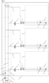
- Fig.1 shows a system according to the invention for supplying several consumer units 1 arranged in a building 6 with exergy in the form of heat.
- the system consists of a low-temperature circuit 3, several consumer units 1, each of which has at least one first high-temperature circuit 5, and decentrally arranged heat pumps 4, with each consumer unit 1 being assigned a heat pump 4.
- Each consumer unit 1 within the building 6 is assigned a heat pump 4.
- the third consumer unit 1 is supplied with exergy for heating or cooling from another source.
- each consumer unit 1 is assigned a further heat pump. According to the invention, however, a heat pump 4 is provided which is assigned to a consumer unit 1.
- the heat pump can be a reversible heat pump, i.e. it can be used to High temperature cycle 5 To supply or remove exergy in the form of heat.
- the low-temperature circuit 3 of the system according to the invention comprises a pump 16, which in the present embodiment is arranged in the basement 6a of the building 6 and circulates a heat transfer medium in the low-temperature circuit 3 in order to extract low-temperature heat from a low-temperature energy source 2.
- the low-temperature circuit 3 is formed by a main flow line 7 and a main return line 9, wherein the pump 16 is arranged in the main flow line 7 and transports the heat transfer medium of the low-temperature circuit 3 to the heat pumps 4 of the consumer units 1 and supplies their primary sides with low-temperature heat.
- the main flow line 7 and the main return line 9 run vertically within the building and lead to each floor, with the direct supply of the heat transfer medium of the low-temperature circuit 3 to the individual heat pumps 4 via a first group of branch lines 8, which are correspondingly smaller in size than the main flow line 7.
- the main flow line 7 and the main return line 9 are located partially within the building 6, namely from the pump 16 located in the basement 6a.
- the distribution of the heat transfer medium of the low-temperature circuit 3 via the main flow line 7 and the branch lines 8 to the heat pumps 4 and the return via the branch lines 10 to the main return line 9 thus takes place entirely within the building.
- the heat transfer medium here has temperatures between -15°C and 25°C in the main flow line and temperatures 2K to 20K lower in the main return line and does not have to be heated before being transported to the consumer units, heated, exergy losses during transport can be kept low due to the small temperature difference to the temperature inside the building.
- thermoelectric heat pumps are used purely as an example.
- heat is therefore extracted from the heat transfer medium of the low-temperature circuit 3 on their primary sides, as is known per se, so that the heat transfer medium of the low-temperature circuit 3 cools down and the coolant of the heat pumps 4 is heated or overheated.
- the coolant of the heat pumps 4 is further heated or overheated, so that exergy in the form of heat can be released on the secondary sides of the heat pumps 4 to the first high-temperature circuits 5 of the consumer units 4.
- the term high-temperature circuit 5 is not necessarily to be understood as a circuit whose heat transfer medium has a "high" temperature, but is intended to enable a distinction to be made from the low-temperature circuit 3.
- the flow temperature of the heat transfer media of the first high-temperature circuits 5 is in any case higher than the flow temperature of the heat transfer medium of the low-temperature circuit 3.
- first high-temperature circuits 5 their flow temperature can be between 20°C and 70°C.
- a first high-temperature circuit 5 can be an underfloor heating system, so that the flow temperature of the heat transfer medium of such a first high-temperature circuit 5, which circulates by means of a pump 18, can be between 28°C and 35°C.
- a first high-temperature circuit 5 can also be a radiator circuit or a domestic water circuit, with correspondingly higher flow temperatures of the heat transfer medium of the first high-temperature circuit 5.
- the first high-temperature circuits 5 are typically underfloor heating systems that are operated with a maximum flow temperature of the heat transfer medium of approximately 35°C, so that the difference between the flow temperature of the heat transfer medium of the low-temperature circuit 3 and the flow temperatures of the heat transfer medium of the first high-temperature circuits 5 of the consumers 1 is not too great and the heat pumps 4 can be operated economically accordingly.
- the heating loops of the underfloor heating systems are provided with the reference number 23. In the event that the first high-temperature circuit 5 is a heating circuit with radiators, the symbol provided with the reference number 23 represents one or more radiators.
- a valve 11 is arranged in each of the branch lines 10, via which at least the inflow of the heat transfer medium of the low-temperature circuit 3 to the respective consumer units 1 can be regulated.
- the valve 11 is a pressure-independent control valve, which guarantees a defined volume flow in the two-line 10 that is independent of the pressure.
- the pressure-independent control valve is part of a control circuit (not shown) and is controlled, for example, depending on the load requirement of the associated heat pump, i.e. depending on the load requirement of the associated heat pump, the pressure-independent control valve enables a larger volume flow in the corresponding branch line 10 or a lower volume flow.
- an arrangement of the pressure-independent control valve 11 is also possible in the respective branch line 8.
- the arrangement in the branch lines 10, i.e. after the consumer units 1, is advantageous because in this case the pressure is already reduced by the consumers of the consumer units 1 and is therefore lower at the valve 11, which allows for finer control due to the lower effort required than if these were arranged in the branch lines 8.
- requirements concerning the control of the pressure-independent control valve 11 can come from the first and/or second high-temperature circuit 5,15.
- predictive control signals can be used to control the control valve 11 for system optimization.
- a mixing valve 17, preferably a three-way mixing valve, can be provided in the main flow line 7, preferably in front of the first consumer unit 1, via which the cooled heat transfer medium in the main return line 9 can be mixed into the main flow line 7.
- the waste heat from consumer units 1 with lower heat requirements can thus be used. to heat the heat transfer medium of the main flow line 7.
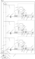
- Fig.2 shows a system according to the invention for supplying several consumer units 1 arranged in a building with exergy in the form of heat as described in Fig.1 shown, but with two high-temperature circuits 5.15 per consumer unit 1.
- the first high-temperature circuit 1 is, as already mentioned in Fig.1 shown, is a heating circuit including pump 18.
- the second high-temperature circuit 15 is a service and/or drinking water circuit, which also has a pump 18 and can transfer heat to a hot water tank 22.
- the heat transfer medium of the low-temperature circuit 3 is used to supply the heating circuits 5 and domestic water/drinking water circuits 15 of the consumer units 1 together with exergy in the form of heat via the respective associated heat pumps 4, while in the case of the system shown in Fig.1
- only one high-temperature circuit 5 (heating circuit) per consumer unit 1 is supplied with exergy in the form of heat via the heat transfer medium of the low-temperature circuit 3 and the heat pumps 4.
- Fig.1 and 2 are therefore similar as regards the supply of the primary sides of the heat pumps 4 with low-temperature heat from the low-temperature circuit 3, but differ as regards the consumers per consumer unit 1.
- Fig.3 shows a further embodiment of a system according to the invention for supplying several arranged in a building Consumer units 1 with exergy in the form of heat.
- the systems shown allow the Fig.3
- the system shown also serves to supply the consumer units with exergy in the form of cold.
- a first heat exchanger 12 is provided for each consumer unit 1, which can be fed on one side with low-temperature heat from the low-temperature circuit 3 and on the other side with the heat transfer medium from the first high-temperature circuit 5 of the consumer unit 1.
- a switching valve 13 is provided for each consumer unit 1, which makes it possible to direct the heat transfer medium of the low-temperature circuit 3 transported via the respective branch line 8 to the first heat exchanger 12.
- the switching valve 13 can completely prevent this supply, whereby the volume flow of the heat transfer medium of the low-temperature circuit 3 transported via the branch line 8, as in the case of the system according to Fig.2 , can be transported to the heat pump 4 assigned to the respective consumer unit 1.
- the first high-temperature circuit 5 is opposite the one in Fig.2 illustrated system is expanded in such a way that it is routed via the first heat exchanger 12.
- the first high-temperature circuit 5 feeds the heat exchanger 12 via a heat dissipation section 5a, which forms part of the high-temperature circuit 5, so that, for example, in summer, when the high-temperature circuit 5 is not needed for heating purposes, the heat transfer medium of the high-temperature circuit 5 can absorb heat via its heating surfaces 23, can be transported via a branch from the return of the first high-temperature circuit 5 to the first heat exchanger 12, where it can release heat to the heat transfer medium of the low-temperature circuit 3 and subsequently, cooled, is routed into the flow of the high-temperature circuit 5, which is secured with a check valve 21, back to the heating surfaces 23, which in this case act as cooling surfaces, because the heat transfer medium has a lower temperature than the environment.
- the heat delivered to the heat transfer medium of the low-temperature circuit 3 via the first heat exchanger 12 increases its temperature in the branch line 8 feeding the consumer unit 1, so that the associated heat pump 4 can be fed with warmer heat transfer medium of the low-temperature circuit 3 on its primary side and thus less exergy in the form of electricity is required to supply the high-temperature circuit 5 with exergy in the form of heat, wherein the high-temperature circuit outlet 5 in this application is only required to supply the second heat exchanger 14 with heat for the second high-temperature circuit 15 (service water/drinking water circuit) if required, by adjusting the corresponding changeover valve 20 in the first high-temperature circuit 5 so that the entire volume flow of the heat transfer medium of the first high-temperature circuit 5 coming from the heat pump 4 is directed to the second heat exchanger 14 in order to release heat there and then, bypassing the heating surfaces 23, into the Return flow of the first high-temperature circuit 5.
- the heat transfer medium of the low-temperature circuit 3 heated by means of the first heat exchanger 12 is transported without heat being released to the heat pump 4 via the branch line 10 into the main return line 9, where it contributes to the general increase in temperature of the heat transfer medium of the low-temperature circuit 3, whereby other consumer units 1 that require heat can save exergy.
- the waste heat from one of the consumer units 1, which enables the cooling of this consumer unit 1 can be used to operate the heat pumps 4 of other consumer units 1 more exergy-efficiently, since less exergy has to be supplied via these heat pumps in order to supply the respective first high-temperature circuit 5 (indirectly the respective second high-temperature circuit 15) with the required heat.
- the switching valve 13 can also be switched in such a way that the first heat exchanger 12 is not flowed through by the heat transfer medium of the low-temperature circuit 3, but the respective heat pump 4 is in operation, whereby active cooling of the heat transfer medium of the first high-temperature circuit 5 is possible.
- the Fig.3 The system described thus enables passive cooling via the first heat exchanger 12 (when the heat pump 4 is at a standstill) and active cooling with the heat pump 4 in operation when the first heat exchanger 12 is not flowing through.
- the heat transfer medium of the low-temperature circuit 3 first flows through the first heat exchanger 12 and then absorbs additional heat from the first high-temperature circuit 5 on the primary side of the associated, reversibly operated heat pump 4.
- Fig.4 finally shows a system like in Fig.1 shown, but with a heat dissipation section 5a, as in Fig.3 shown.
- the system shown can be used to easily implement active and passive cooling of the consumer units.
- the consumer units 1 can be supplied with exergy in the form of cold as in Fig.4 presented, supplied.
- the fitting 11, in particular the pressure-independent control valve 11, the heat pump 4 and the second heat exchanger 14 are arranged in a common housing.
- the fitting 11, in particular the pressure-independent control valve 11, the heat pump 4 and the first heat exchanger 12 and the second heat exchanger 14 are arranged in a common housing.
- the fitting 11, in particular the pressure-independent control valve 11, the heat pump 4 and the first heat exchanger 12 are arranged in a common housing.
Landscapes
- Engineering & Computer Science (AREA)
- Physics & Mathematics (AREA)
- Thermal Sciences (AREA)
- Chemical & Material Sciences (AREA)
- Combustion & Propulsion (AREA)
- Mechanical Engineering (AREA)
- General Engineering & Computer Science (AREA)
- Water Supply & Treatment (AREA)
- Other Air-Conditioning Systems (AREA)
- Steam Or Hot-Water Central Heating Systems (AREA)
Priority Applications (2)
| Application Number | Priority Date | Filing Date | Title |
|---|---|---|---|
| EP23154468.5A EP4411253A1 (fr) | 2023-02-01 | 2023-02-01 | Système d'alimentation d'une pluralité d'unités de consommation placées dans un bâtiment en exergie |
| EP24155214.0A EP4411254B1 (fr) | 2023-02-01 | 2024-02-01 | Système d'alimentation d'une pluralité d'unités de consommation placées dans un bâtiment en exergie |
Applications Claiming Priority (1)
| Application Number | Priority Date | Filing Date | Title |
|---|---|---|---|
| EP23154468.5A EP4411253A1 (fr) | 2023-02-01 | 2023-02-01 | Système d'alimentation d'une pluralité d'unités de consommation placées dans un bâtiment en exergie |
Publications (1)
| Publication Number | Publication Date |
|---|---|
| EP4411253A1 true EP4411253A1 (fr) | 2024-08-07 |
Family
ID=85158433
Family Applications (2)
| Application Number | Title | Priority Date | Filing Date |
|---|---|---|---|
| EP23154468.5A Withdrawn EP4411253A1 (fr) | 2023-02-01 | 2023-02-01 | Système d'alimentation d'une pluralité d'unités de consommation placées dans un bâtiment en exergie |
| EP24155214.0A Active EP4411254B1 (fr) | 2023-02-01 | 2024-02-01 | Système d'alimentation d'une pluralité d'unités de consommation placées dans un bâtiment en exergie |
Family Applications After (1)
| Application Number | Title | Priority Date | Filing Date |
|---|---|---|---|
| EP24155214.0A Active EP4411254B1 (fr) | 2023-02-01 | 2024-02-01 | Système d'alimentation d'une pluralité d'unités de consommation placées dans un bâtiment en exergie |
Country Status (1)
| Country | Link |
|---|---|
| EP (2) | EP4411253A1 (fr) |
Citations (3)
| Publication number | Priority date | Publication date | Assignee | Title |
|---|---|---|---|---|
| EP2322880B1 (fr) * | 2009-11-16 | 2016-03-09 | Vaillant GmbH | Système de pompes à chaleur |
| US20180335219A1 (en) * | 2015-11-20 | 2018-11-22 | Sens Geoenergy Storage Ab | Heat pump system and method for controlling a heat pump system |
| EP3252384B1 (fr) * | 2016-05-31 | 2020-01-29 | Daikin Industries, Ltd. | Appareil de chauffage des locaux et approvisionnement en eau chaude |
Family Cites Families (1)
| Publication number | Priority date | Publication date | Assignee | Title |
|---|---|---|---|---|
| DE202011106855U1 (de) * | 2011-10-15 | 2011-11-29 | Institut Für Solarenergieforschung Gmbh | Wärmeversorgungssystem mit dezentralen Wärmepumpen und gebäudeintegriertem Wärmequellennetz für Umweltwärme, insbesondere Erdwärme, Umgebungsluft, Abwärme oder/und Solarwärme |
-
2023
- 2023-02-01 EP EP23154468.5A patent/EP4411253A1/fr not_active Withdrawn
-
2024
- 2024-02-01 EP EP24155214.0A patent/EP4411254B1/fr active Active
Patent Citations (3)
| Publication number | Priority date | Publication date | Assignee | Title |
|---|---|---|---|---|
| EP2322880B1 (fr) * | 2009-11-16 | 2016-03-09 | Vaillant GmbH | Système de pompes à chaleur |
| US20180335219A1 (en) * | 2015-11-20 | 2018-11-22 | Sens Geoenergy Storage Ab | Heat pump system and method for controlling a heat pump system |
| EP3252384B1 (fr) * | 2016-05-31 | 2020-01-29 | Daikin Industries, Ltd. | Appareil de chauffage des locaux et approvisionnement en eau chaude |
Also Published As
| Publication number | Publication date |
|---|---|
| EP4411254A1 (fr) | 2024-08-07 |
| EP4411254B1 (fr) | 2026-04-29 |
Similar Documents
| Publication | Publication Date | Title |
|---|---|---|
| EP3032181B1 (fr) | Systeme de chauffage comprenant un chauffe-eau | |
| EP3667182B1 (fr) | Installation de pompe à chaleur | |
| EP3447403B1 (fr) | Procédures de fonctionnement pour installations de récupération de chaleur, unité d'échange de chaleur air/fluide et installation de récupération de chaleur | |
| DE102010016343A1 (de) | Vorrichtung zur Wärmeversorgung von Gebäuden | |
| DE202014103193U1 (de) | Zirkulationsleitung für Kaltwasser | |
| EP3835666B1 (fr) | Système de bâtiment destiné à la climatisation et à l'approvisionnement en chaleur | |
| EP2784400B1 (fr) | Procédé et dispositif d'injection de chaleur depuis un réseau de chaleur | |
| DE102005061599A1 (de) | Modulares Kühlsystem und Kälteerzeugungseinrichtung für ein solches Kühlsystem | |
| EP3136005B1 (fr) | Procede de fonctionnement d'une installation de chauffage | |
| DE102019111173A1 (de) | Kaltwärmenetz mit Booster-Wärmepumpe | |
| EP3482136B1 (fr) | Système de chauffage | |
| DE102013009608A1 (de) | Wärmequellen-Auswahlvorrichtung für ein Wärmequellensystem, ein Verfahren davon und ein Wärmequellensystem | |
| CH708598A1 (de) | Anordnung und Verfahren zum Raumtemperieren und Warmwasserbereitstellen. | |
| AT521703A4 (de) | Warmwasserbereitungsanlage | |
| DE102007063009B4 (de) | Verfahren zur Belüftung von Objekten und Vorrichtung zur Belüftung von Objekten, insbesondere raumlufttechnische Anlage | |
| DE102015117851B4 (de) | Fluidsystem und Verfahren zur Steuerung eines Fluidsystems | |
| EP4411253A1 (fr) | Système d'alimentation d'une pluralité d'unités de consommation placées dans un bâtiment en exergie | |
| EP3980695A1 (fr) | Procédé pour faire fonctionner une installation de chauffage comprenant une pompe de chaleur et installation de chauffage | |
| AT511697A4 (de) | Vorrichtung zur erwärmung von brauchwasser | |
| EP2932168B1 (fr) | Système de pompe à chaleur et procédé pour faire fonctionner un système de pompe à chaleur | |
| EP3367005B1 (fr) | Système de chauffage | |
| DE102022113670B3 (de) | Lüftungsanlage und Gebäude | |
| AT10232U1 (de) | Heizungsanlage mit mindestens einer wärmequelle | |
| DE102018104344A1 (de) | System zur Fluiderwärmung und Verfahren der Regelung der Temperatur in einem Fluidspeicher | |
| DE9414055U1 (de) | Zentralheizsystem für Gebäude |
Legal Events
| Date | Code | Title | Description |
|---|---|---|---|
| PUAI | Public reference made under article 153(3) epc to a published international application that has entered the european phase |
Free format text: ORIGINAL CODE: 0009012 |
|
| STAA | Information on the status of an ep patent application or granted ep patent |
Free format text: STATUS: THE APPLICATION HAS BEEN PUBLISHED |
|
| AK | Designated contracting states |
Kind code of ref document: A1 Designated state(s): AL AT BE BG CH CY CZ DE DK EE ES FI FR GB GR HR HU IE IS IT LI LT LU LV MC ME MK MT NL NO PL PT RO RS SE SI SK SM TR |
|
| STAA | Information on the status of an ep patent application or granted ep patent |
Free format text: STATUS: THE APPLICATION IS DEEMED TO BE WITHDRAWN |
|
| 18D | Application deemed to be withdrawn |
Effective date: 20250208 |