EP4411364A2 - Système et procédé de détection de fuite à haute tension alternative-directe - Google Patents
Système et procédé de détection de fuite à haute tension alternative-directe Download PDFInfo
- Publication number
- EP4411364A2 EP4411364A2 EP24175842.4A EP24175842A EP4411364A2 EP 4411364 A2 EP4411364 A2 EP 4411364A2 EP 24175842 A EP24175842 A EP 24175842A EP 4411364 A2 EP4411364 A2 EP 4411364A2
- Authority
- EP
- European Patent Office
- Prior art keywords
- high voltage
- package
- voltage
- electrode
- detection
- Prior art date
- Legal status (The legal status is an assumption and is not a legal conclusion. Google has not performed a legal analysis and makes no representation as to the accuracy of the status listed.)
- Pending
Links
Images


Classifications
-
- G—PHYSICS
- G01—MEASURING; TESTING
- G01M—TESTING STATIC OR DYNAMIC BALANCE OF MACHINES OR STRUCTURES; TESTING OF STRUCTURES OR APPARATUS, NOT OTHERWISE PROVIDED FOR
- G01M3/00—Investigating fluid-tightness of structures
- G01M3/40—Investigating fluid-tightness of structures by using electric means, e.g. by observing electric discharges
-
- G—PHYSICS
- G01—MEASURING; TESTING
- G01M—TESTING STATIC OR DYNAMIC BALANCE OF MACHINES OR STRUCTURES; TESTING OF STRUCTURES OR APPARATUS, NOT OTHERWISE PROVIDED FOR
- G01M3/00—Investigating fluid-tightness of structures
- G01M3/02—Investigating fluid-tightness of structures by using fluid or vacuum
- G01M3/04—Investigating fluid-tightness of structures by using fluid or vacuum by detecting the presence of fluid at the leakage point
- G01M3/16—Investigating fluid-tightness of structures by using fluid or vacuum by detecting the presence of fluid at the leakage point using electric detection means
-
- G—PHYSICS
- G01—MEASURING; TESTING
- G01N—INVESTIGATING OR ANALYSING MATERIALS BY DETERMINING THEIR CHEMICAL OR PHYSICAL PROPERTIES
- G01N27/00—Investigating or analysing materials by the use of electric, electrochemical, or magnetic means
Definitions
- the invention relates to the technical field of leak detection, specifically high-voltage leak detection, methods and systems implementing such methods for use in detecting and signaling leaks, tears, breaks, or other imperfections in packaging containers, including, but not limited to, vials, syringes, ampoules, pouches, aluminium pouches, and I.V. bags for sensitive perishable or non-perishable goods.
- HVLD high-voltage leak detection
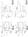
- FIGs. 1A - 1D The principle of conventional HVLD is shown in Figs. 1A - 1D .
- a control vial 001 without defect and filled with a liquid product inspected by conventional HVLD is shown in Fig. 1A .
- Fig. 1B the testing of the control vial of Fig. 1A is shown in a simplified electrical-equivalent circuit.
- the testing of a defective vial 002 filled with a liquid product is shown in Fig. 1C being inspected by conventional HVLD.
- Fig. 1D represents the simplified electrical equivalent circuit for the defective vial in Fig. 1C .
- the electrical equivalent circuits are based on a simplified model and that more complex models could be created.
- conventional HVLD testing involves placing a container 007 between two electrodes 003, 005 and applying AC high voltage 023 to the circuit, with one electrode being an inspection electrode 003 and the other electrode being a detection electrode 005.
- the two electrodes are oriented such that the container to be tested is oriented between the two electrodes without making physical contact with either electrode.
- the container would then have two specific impedances and a specific resistance: a specific impedance at the container wall across from the inspection electrode R 1 + 1 j ⁇ C 1 , a specific impedance at the container wall across from the detection electrode R 2 + 1 j ⁇ C 2 , and a specific resistance of the product inside the container R Pro .
- the resulting current through the non-defective container is represented as I WD .
- a defective container will have a larger electric current present (I D ) than a container without defect (I WD ).
- C 1 , R 1 , C 2 , R 2 , R Pro are variables and change depending on the amplitude of the applied AC high voltage, material characteristics (such as dielectric strength of the container and liquid product), and the conductivity of the liquid product.
- the risk of applying too large of a voltage is that applied high voltage may create an arc or spark over the impedances listed above and cause what appears as a false leak. Therefore it is necessary in conventional HVLD technology to reach the highest possible voltage, in order to get better sensitivity of the leak detection, without sparking around the container to break down the insulation of the container and the liquid product inside the container.
- the risk of detecting false leaks using the conventional HVLD is especially high with low-conductivity products.
- Conventional HVLD also faces mechanical disadvantages, as the components necessary to create a testing device employing conventional HVLD are heavy and unwieldy. This makes a conventional HVLD benchtop tool impractical.
- DC HVLD a container to be tested for leaks is instead charged purely with DC high voltage. The presence of leaks is determined through the detection of charging and neutralizing currents.
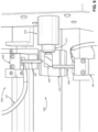
- the Takeda system uses DC high voltage to charge a container, as shown in Fig. 2 .
- the container 105 with fluid product contained within is placed between an anode rod 109, an auxiliary electrode rod 111, and a cathode plate 107.
- the anode rod 109 is connected to positive side of the DC high voltage source 115.
- the cathode plate 107 and the auxiliary rod 111 are connected to a negative side of the DC high voltage source 115 through a measuring resistance 117 and a switch 119 respectively as shown in Fig. 2 .
- the auxiliary electrode 111 When the switch 119 is turned off, the auxiliary electrode 111 is not connected to the negative side of the DC high voltage source 115 then neither electrical charging nor discharging takes place. However if the switch 119 is turned on, the auxiliary electrode 111 is connected to the negative side of the DC high voltage source 115, and a spark discharge occurs between the auxiliary electrode 111 and anode rod 109 which simultaneously causes the electrical charge at the neck portion of the ampoule 105 to be discharged. Meanwhile, a discrimination circuit 121 is used across resistor 117 to detect the potential developed across it.
- a neutralizing current i 1 is caused to flow from the auxiliary electrode rod 111 to the cathode plate 107, and is detected by the discrimination circuit 121.
- the neutralizing current i 1 normally reaches its maximum value immediately after initiation of the discharge by the auxiliary electrode 111, and subsequently decreases rapidly, as shown in Fig. 3 .
- the neutralizing current (i 1 ) caused to flow obtains a peak value of one unit as shown in Fig. 3 .
- a neutralizing current i 3 of about two units or more is caused to flow, as shown in Fig. 3 , where i 1 is the neutralizing current for containers without defect and i 3 is the neutralizing current for containers with defect.
- Fig. 4 shows an equivalent circuit for the Takeda DC HVLD system shown in Fig. 2 .
- a major disadvantage of the DC HVLD method and system is the lack of continuity and consistency in testing.
- the DC HVLD system is a discontinuous test since it is a discontinuous signal which is discretely created and sampled. Each package tested must be charged before being discharged through the discrimination circuit for a single measurement. The charging and discharging of the packages takes place one after another. This makes using the DC HVLD system for an online inspection in a production line almost impossible due to its slow speed and discontinuous nature.
- Another disadvantage of the DC HVLD system is the discontinuous nature of the signal applied during testing due to the charging and discharging required.
- the high voltage discharge used in the DC HVLD system of Takeda can be very stochastic. Since its detected signal is a discrete waveform, the signal in the DC HVLD does not have a certain frequency, phase, or amplitude. The amplitude can vary strongly dependent on the amount of charging and discharging which occurs, and can vary based on the distance between the electrodes and the defect.
- DC HVLD requires that the anode rod is stationary at top of the package. This technology can be used only for inspection of ampoules. Containers like vials with an aluminum cap or syringes with a metal needle cannot be inspected by the DC HVLD since the metals are highly conductive in comparison to glass or plastic and lead to false positive results.
- DC HVLD also requires that the cathode plate is in contact with the package. Contact with packages during testing is undesirable for online testing using rigid electrodes, as such contact is considered to be a destructive method of on-line testing.
- the current invention solves the problem of sensitive product exposure to high voltage, undesirable levels of ozone production, and false-positive leak detections of conventional HVLD and the structural inflexibility, online inspection limitations, and variability of DC HVLD by applying an AC voltage with a DC high voltage offset to a leak detection, which can be explained by using a simplified electrical equivalent circuits in Fig. 6A to 6D , where the AC current can flow through all components within the circuit while the DC current can only flow through the path without capacitors.
- the electrical equivalent circuits are based on a simplified model and that more complex models could be created.
- the alternating-direct high voltage (ADHV) technique includes placing a container to be tested between a detection electrode and an inspection electrode.
- a high voltage generation circuit is used for generating a high voltage, the high voltage generation circuit including a pulse autotransformer, a high voltage rectifier, and a high voltage control board. The container is then positioned between the inspection electrode and the detection electrode.
- High voltage, AC voltage with DC voltage offset, is then generated through the high voltage generation circuit, such that an electrical current is applied to the container through the inspection electrode and the electrical current through the container is detected by the detection electrode and processed by the detection board.
- the electrical current through the container can be explained based on electrical equivalent circuits.
- I D AC HV R Pro + Z 2 + DC HV R Pro + R 4
- AC HV AC part of high-voltage.
- DC HV DC offset of high-voltage.
- C 1 " and “R 1 " are specific capacitance and resistance, respectively, of a first wall of container.
- C 2 " and “R 2” are specific capacitance and resistance, respectively, of a second wall of container.
- R 3 specific high-Ohm resistance of the first wall of container.
- R 4 specific high-Ohm resistance of the second wall of container.
- R Pro specific high-Ohm resistance of liquid product inside container.
- f is frequency of AC high voltage.
- a preferred embodiment of apparatus for ADHV leak detection includes: an inspection electrode electrically connected to a high voltage rectifier; a first DC voltage power supply electrically connected to the pulse autotransformer, the pulse autotransformer further electrically connected to a high voltage control board, and to a high voltage rectifier; a second DC voltage power supply electrically connected to the high voltage control board, a detection board, a programmable logic controller, and a display to supply them by electric power; and a detection electrode electrically connected to a detection board, the detection board further electrically connected to the programmable logic controller, the programmable logic controller further electrically connected to the display, wherein the detection electrode and the inspection electrode are positioned such that a package fits between the detection electrode and the inspection electrode, and AC high voltage with a DC high voltage offset is applied through the inspection electrode.
- a preferred embodiment of a method for ADHV leak detection includes: placing a container between a detection electrode and an inspection electrode connected through a high voltage generation circuit for generating a high voltage, the high voltage generation circuit including a pulse autotransformer, a DC voltage power supply, a high voltage rectifier, and a high voltage control board; creating a capacitive impedance between the product and the detection electrode and between the inspection electrode and the product; generating a high voltage through the high voltage generation circuit, such that an electrical current an electrical voltage is applied to the container through the inspection electrode and the electrical current through the container is detected by the detection electrode and processed by the detection circuit; processing a change in the electrical current through the container at the detection electrode; and identifying a leak in the container through the change in electrical current.
- ADHV Alternating-Direct High Voltage relating to the use of an AC high voltage with a DC high-voltage offset.
- electrically connected refers to any known method of connecting one or more objects or elements in an electrical circuit such that an electrical signal or electrical current may be transmitted between the objects. Commonly, wire, cables, lines, or similar products are used to electrically connect one or more objects in an electrical circuit.
- a preferred embodiment of a method 300 for detecting leaks in packaging includes generating an AC high voltage with a DC high voltage offset in a circuit.
- a package 305 is placed between an inspection electrode 301 and a detection electrode 303, which are located within the circuit.
- the inspection electrode 301 applies the AC high voltage 323 with the DC high voltage offset 329 to the package 305.
- Current flow through the package is then detected by the detection electrode.
- a detection board then processes the current flow to determine if a leak 311 is present in the package. If a leak is present, a signal is sent to a display to notify a user.
- FIG. 6A shows a package 305 without defect being tested using the ADHV method.
- Fig. 6B shows an equivalent electrical circuit representation of the testing in Fig. 6A.
- Fig. 6C shows a package 305 with defect being tested using the ADHV method.
- Fig. 6D shows an equivalent electrical circuit representation of the testing in Fig. 6C .
- C 1 represents specific capacitance of a first wall of package
- R 1 represents specific resistance of the first wall of package
- C 2 represents specific capacitance of a second wall of package
- R 2 represents specific resistance of the second wall of package
- R 3 represents specific high-Ohm resistance of the first wall of package
- R 4 represents specific high-Ohm resistance of the second wall of package
- R Pro represents specific high-Ohm resistance of liquid material inside container
- f represents frequency of AC high voltage
- L 0 represents ideal inductor in the simplified equivalent circuit for blocking AC current
- C 0 represents ideal capacitor in the simplified equivalent circuit for blocking DC current
- I WD represents current 307 through a container without defect
- I D represents current 309 through a defective container.
- C 1 , R 1 , C 2 , R 2 , R 3 , R 4 , R Pro are variables and change depending on the amplitude of the applied AC high voltage, level of the applied DC high voltage offset, material characteristics such as dielectric strength of the container and liquid product, and the conductivity of the liquid product.
- the package With both AC and DC voltages applied to the circuit, material within the package is only exposed to DC high voltage if a defect exists in the package.
- the package is made of an insulator which attenuates the applied DC high voltage strongly.
- both AC and DC currents flow through the inspected package.
- the AC current can flow through all components in the circuit while the DC current can only flow through the path without capacitors.
- the AC high voltage with a DC high voltage offset is generated using either a pulse autotransformer or a pulse transformer, high voltage control board, a high-voltage rectifier, and a DC voltage power supply.
- the inspection electrode can be rigid, semi-rigid, or flexible in the form of a brush, a rod, steel, or similarly shaped object. Further, the inspection electrode can be made of metals, conductive polymers, or any other kind of conductive material. During application of the AC high voltage with a DC high voltage offset, the inspection electrode can be touching the package or a small air gap can exist between the package and the inspection electrode.
- the detection electrode can be rigid, semi-rigid, or flexible in the form of a brush, a rod, steel, or similarly shaped object. Further, the detection electrode can be made of a metal, metal alloys, conductive polymers, or any other kind of conductive material. During detection of the current produced with the AC high voltage with a DC high voltage offset, the detection electrode can be touching the package or a small air gap can exist between the package and the detection electrode.
- the package can be in the form of a vial, a syringe, an ampoule, a pouch, a bag, a blow-seal, and any other kind of container made of plastic, glass, aluminum foils, or any other kind of material suitable to be filled with medicinal, food, or similar perishable or sensitive product.
- an AC high voltage with a DC high voltage offset is generated in a circuit.
- a package is placed between an inspection electrode and a detection electrode, which are located within the circuit.
- the package is rotated along a single axis between the inspection electrode and the detection electrode. Further, the inspection electrode and detection electrode moved along the length of the package as the package is rotated.
- the inspection electrode applies the AC high voltage with the DC high voltage offset to the package.
- Current flow through the package is then detected by the detection electrode.
- a detection board then processes the current flow to determine if a leak is present in the package using the same equations as the preferred embodiment. If a leak is present, a signal is sent to a display for a user to visualize.
- the AC high voltage with a DC high voltage offset is generated using either a pulse autotransformer or a pulse transformer, high voltage control board and a high-voltage rectifier.
- the inspection electrode can be rigid, semi-rigid, or flexible in the form of a brush, a rod, steel, or similarly shaped object. Further, the inspection electrode can be made of metals, conductive polymers, or any other kind of conductive material. During application of the AC high voltage with a DC high voltage offset, the inspection electrode can be touching the package or a small air gap can exist between the package and the inspection electrode.
- the detection electrode can be rigid, semi-rigid, or flexible in the form of a brush, a rod, steel, or similarly shaped object. Further, the detection electrode can be made of a metal, metal alloys, conductive polymers, or any other kind of conductive material. During detection of the current produced with the AC high voltage with a DC high voltage offset, the detection electrode can be touching the package or a small air gap can exist between the package and the detection electrode.
- the package can be in the form of a vial, a syringe, an ampoule, a pouch, and any other kind of container made of plastic, glass, aluminum foils, or any other kind of material suitable to be filled with medicinal, food, or similar product.
- a further embodiment of the method includes generating an AC high voltage with a DC high voltage offset in a circuit.
- a package is placed on a conveyor.
- the conveyor moves the package between an inspection electrode and a detection electrode, which are located within the circuit.
- the inspection electrode applies the AC high voltage with the DC high voltage offset to the package.
- Current flow through the package is then detected by the detection electrode.
- a detection board then processes the current flow to determine if a leak is present in the package using the same equations as the preferred embodiment. If a leak is present, a signal is sent to a display for a user to visualize.
- the AC high voltage with a DC high voltage offset is generated using either a pulse autotransformer or a pulse transformer, a high-voltage rectifier and a DC voltage power supply.
- the inspection electrode can be rigid, semi-rigid, or flexible in the form of a brush, a rod, steel, or similarly shaped object. Further, the inspection electrode can be made of metals, conductive polymers, or any other kind of conductive material. During application of the AC high voltage with a DC high voltage offset, the inspection electrode can be touching the package or a small air gap can exist between the package and the inspection electrode.
- the detection electrode can be rigid, semi-rigid, or flexible in the form of a brush, a rod, steel, or similarly shaped object. Further, the detection electrode can be made of a metal, metal alloys, conductive polymers, or any other kind of conductive material. During detection of the current produced with the AC high voltage with a DC high voltage offset, the detection electrode can be touching the package or a small air gap can exist between the package and the detection electrode.
- the package can be in the form of a vial, a syringe, an ampoule, a pouch, a bag, a blow-seal, and any other kind of container made of plastic, glass, aluminum foils, or any other kind of material suitable to be filled with medicinal, food, or similar perishable or sensitive product.
- a device for applying the ADHV testing method There are many embodiments of a device for applying the ADHV testing method. Such embodiments vary based on the types of packages to be tested and whether packages are to be tested one at a time, also known as off-line testing, or if multiple packages are to be tested continuously without user manipulation, also known as on-line testing.
- a preferred embodiment of a leak detection circuit 200 includes an inspection electrode 201 connected to high voltage rectifier 205 by a high voltage cable 203, the high voltage rectifier further electrically connected to a pulse autotransformer 208, a first DC voltage power supply 209 electrically connected to the pulse autotransformer 208, the pulse autotransformer electrically connected to a high voltage control board 211, the high voltage control board 211 electrically connected to a programmable logic controller 217, a detection electrode 227 connected to a detection board 219 via a shielded cable 225, the detection board electrically connected to the programmable logic controller, a display 215 electrically connected to the programmable logic controller, a secondary DC power supply 213 electrically connected to the high voltage control board 211, the detection board 219, the programmable logic controller 217, and the display 215, wherein the detection electrode 227 and the inspection electrode 201 are positioned such that a package 202 fits between the detection electrode 227 and the inspection electrode 201
- the AC high-voltage with a DC high-voltage offset may be generated by a means known in the art other than the pulse autotransformer 208 with a DC voltage power supply 213, a high-voltage rectifier 205, and a high voltage control board 211, such as, but not limited to, a pulse transformer 208 with a DC voltage power supply 213, a high-voltage rectifier 205, and a high voltage control board 211.
- the inspection electrode 201 is electrically connected to the high-voltage rectifier 205, which is electrically connected to the pulse transformer 208.
- the high voltage control board 211 can be, but is not limited to, combination of microprocessor and a MOSFET or IGBT.
- the microprocessor turns the MOSFET or IGBT on and off by generating pulses with certain duration and duty cycle which switches the current flow from the DC power supply 209 through the high voltage pulse autotransformer 208 or the high voltage pulse transformer 208 on and off. Since the current through the high voltage pulse autotransformer 208 or the high voltage pulse transformer 208 switched on and off AC high voltage is generated at outputs of the high voltage pulse autotransformer 208 or the high voltage pulse transformer 208.
- the high voltage control board 211 adjusts the amplitude of the generated AC high voltage by changing the duration and the duty cycle of the pulses.
- the high voltage rectifier 205 rectifies the AC high voltage and provides a DC offset to the AC high voltage.
- the AC high voltage with DC offset is applied to the package through the high voltage cable 203 and inspection electrode 201.
- the detection electrode 227 receives the resulting current through the package 202. The current then travels to a current detection board 219, where the current is processed to determine whether or not a leak is present.
- the detection board 219 is electrically connected in to the programmable logic controller 217.
- the detection board 219 processes the received signal and sends the processed signal to the programmable logic controller 217 and the display shows whether a leak is present.
- the programmable logic controller 217 is electrically connected to the current detection board 219, such that the programmable logic controller 217 can be programed to interact with the detection board 219 in the desired manner.
- the programmable logic controller 217 is further electrically connected to the high voltage control board 211 such that the programmable logic controller 217 can be programed to interact with the high voltage control board 211 in the desired manner.
- the display 215 is electrically connected to the programmable logic controller 217 to provide information stored in the programmable logic controller to a user, including audio and visual information.
- the second DC voltage power supply is connected to the high voltage control board 211, the detection board 219, programmable logic controller 217, and display 215 to supply them by electrical power.
- the AC high-voltage with a DC high-voltage offset may generated by a means known in the art other than the pulse autotransformer 207 with the DC voltage power supply 209, the high voltage control board 211, and the high-voltage rectifier 205, such as, but not limited to, a pulse transformer 208 with the DC voltage power supply 209, the high voltage control board 211, and the high-voltage rectifier 205.
- the inspection electrode 201 is electrically connected to the high-voltage rectifier 205, which is electrically connected to the pulse autotransformer 207 or the pulse transformer 208.
- the package 202 may be a vial, a syringe, an ampoule, or other similar pouch, bottle, container, or sealed holder. Further, the package 202 can be made of plastic, glass, or another material which exhibits capacitive and resistive properties. The package is filled with product typically, but not exclusively, including food, medicinal, biological, or other similar products.
- a holder may be used to secure the package 202 during testing. The holder may include, but is not limited to, a tray, a rod with securing mechanism, a belt, or other similar device. Additionally, the holder may be attached to a rotation mechanism that rotates the holder and the package between the inspection and detection electrodes.
- Both the inspection electrode 201 and detection electrode 227 can be shaped differently and made of different materials depending on their application.
- the inspection electrode 201 and detection electrode 227 can be made of a metal, metal alloys, conductive polymers, magnetic materials, or any other kind of conductive material.
- the inspection electrode 201 and detection electrode 227 can be rigid, semi-rigid, or flexible, and in the form of a brush, a rod, a comb, or a similarly shaped object.
- both the inspection electrode 201 and detection electrode 227 can be touching the package 202.
- a small air gap 204 can exist between the package 202 and the inspection electrode 201 and detection electrode 227.
- the small air gap 204 can be between the inspection electrode 201 and the package, and the detection electrode 227 and the package 202.
- the small air gap 204 can be between 0.2 mm to 5 mm wide.
- the inspection electrode 201 and detection electrode 227 should not touch each other during testing, and they should be positioned far enough apart to prevent arcing.
- the inspection electrode 201 and detection electrode 227 may also be movable in relation to the package.
- a sliding mechanism can be attached to either or both of the inspection electrode and detection electrode.
- the sliding mechanism can move along the length of the package and towards or away from the package. This movement allows the electrodes to be moved apart during placement and removal of the package from between the inspection electrode and the detection electrode.
- the movement afforded by the sliding mechanism also allows the inspection electrode and detection electrode to maintain contact with, or an even distance from, a package with slopes, curves or irregular shapes during testing.
- a conveyor may also be used in conjunction with leak detection circuit 200 for on-line testing.
- One or more packages are placed on the conveyor, which moves the package between the inspection electrode 201 and the detection electrode 227.
- the inspection electrode 201 and detection electrode 227 may be configured to touch the package 202 during testing or be spaced to provide an air gap between the electrodes 201 and 227 and the package 202.
- the conveyor can be structured in any way which would permit the inspection electrode 201 be positioned in such a way to apply an AC high voltage with DC high voltage offset to one surface of the package 202 and permit the detection electrode 227 to be positioned to receive the resulting current at an opposing surface of the package 202.
- FIG. 11 provides an example of one possible embodiment of the leak detection circuit 200 coupled with a conveyor.
- the conveyor in Fig. 11 is a series of rollers where a detection electrode is positioned between two rollers and an inspection electrode hangs above the conveyor.
- Another viable organization would be a conveyer system with two belts.
- the electrodes 201 and 227 are placed between the two conveyer belts at a certain distance from each other to prevent a direct spark between the electrodes.
- Use of a conveyor with the leak detection system 200 does not otherwise limit the structural variety of the elements of the preferred embodiment discussed.
- Fig. 7 shows another embodiment of a leak detection system 400, specifically at a testing interface 402 where a package 409 is secured between an inspection electrode 401 and a detection electrode 403.
- a holder 411 secures the package 409, shown in this embodiment as a vial, horizontally during testing.
- a rotation mechanism 413 spins the holder 411 and the package 409 coaxially during testing.
- the inspection electrode 401 and the detection electrode 403 do not touch the package 409 in this embodiment to prevent scratching or marking of the package 409 during testing.
- An inspection sliding mechanism 417 is attached to the inspection electrode 401.
- the inspection sliding mechanism 417 allows the inspection electrode 401 to move horizontally back and forth along the length of the package 409 during testing.
- a detection sliding mechanism 415 is attached to the detection electrode 403.
- the detection sliding mechanism 415 allows the detection electrode 403 to move horizontally back and forth along the length of the package 409 during testing.
- Fig. 8 shows the same embodiment of the leak detection system 400. However, Fig. 8 demonstrates the positioning of the inspection electrode 401 and the detection electrode 403 achievable when attached to the inspection sliding mechanism 417 and detection sliding mechanism 415, respectively. Where Fig. 7 shows the inspection electrode 401 and detection electrode 403 centered, Fig. 8 shows the electrodes 401 and 403 offset as a representation of sliding mechanisms 415 and 417 ability to slide the electrodes 401 and 403 back and forth along the length of the package 409 during testing.
- a high voltage cable 405 connects the inspection electrode 401 of the embodiment shown in Fig. 7 to the remaining elements of the leak detection circuit 200 as described in the preferred embodiment and shown in Fig. 5 .
- the shielded cable 407 connects the detection electrode 403 to the remaining elements of the leak detection circuit 200 as described in the preferred embodiment and shown in Fig 5 .
- Fig. 9 shows another embodiment of a leak detection system 500, specifically at a testing interface 502 where a package 505 is secured between an inspection electrode 501 and a detection electrode 503.
- a holder 517 secures the package 505, shown in this embodiment as a vial, horizontally during testing.
- a rotation mechanism 519 spins the holder 517 and the package 505 coaxially during testing.
- a tray 515 is positioned below the package 505. The inspection electrode 501 and the detection electrode 503 again do not touch the package 505 in this embodiment to prevent scratching or marking of the package 505 during testing.
- An inspection sliding mechanism 509 is attached to the inspection electrode 501.
- the inspection sliding mechanism 509 allows the inspection electrode 501 to move horizontally back and forth along the length of the package 505 during testing.
- a detection sliding mechanism 507 is attached to the detection electrode 503.
- the detection sliding mechanism 507 allows the detection electrode 503 to move horizontally back and forth along the length of the package 505 during testing.
- the electrodes 501 and 503 are offset in Fig. 9 as a representation of the ability of the sliding mechanisms 507 and 509 to slide the electrodes 501 and 503 back and forth along the length of the package 505 during testing. The remaining elements, their variations, and structural cooperation are as described in the preferred embodiment.
- a high voltage cable 511 connects the inspection electrode 501 of the embodiment shown in Fig. 9 to the remaining elements of the leak detection circuit 200 as described in the preferred embodiment and shown in Fig. 5 .
- the shielded cable 513 connects the detection electrode 503 to the remaining elements of the leak detection circuit 200 as described in the preferred embodiment and shown in Fig. 5 .
- the remaining elements, their variations, and structural cooperation are as described in the preferred embodiment.
- Fig. 10 shows yet another embodiment of a leak detection system 600, specifically at a testing interface 602 where a package 613 is secured between an inspection electrode 601 and a detection electrode 603.
- a holder 609 secures the package 613, shown in this embodiment as syringe, horizontally during testing.
- a rotation mechanism 611 spins the holder 609 and the package 613 coaxially during testing.
- a tray 615 is positioned below the package 613.
- the inspection electrode 601 and the detection electrode 603 again do not touch the package 613 in this embodiment to prevent scratching or marking of the package 613 during testing.
- An inspection sliding mechanism 605 is attached to the inspection electrode 601.
- the inspection sliding mechanism 605 allows the inspection electrode 601 to move horizontally back and forth along the length of the package 613 during testing.
- a detection sliding mechanism 607 is attached to the detection electrode 603.
- the detection sliding mechanism 607 allows the detection electrode 603 to move horizontally back and forth along the length of the package 613 during testing.
- the electrodes 601 and 603 are at similar relative positions in Fig. 10 , but are capable of sliding along the length of the package 613 independently as described in previous embodiments.
- the inspection electrode 601 of the embodiment shown in Fig. 10 is connected to the remaining elements associated with the leak detection circuit 200 as described in the preferred embodiment and shown in Fig. 5 .
- the detection electrode 603 is connected to the remaining elements associated with the leak detection circuit 200 as described in the preferred embodiment and shown in Fig 5 .
- the remaining elements, their variations, and structural cooperation are as described in the preferred embodiment.
- Fig. 11 shows a conveyor embodiment of a leak detection system 700, specifically at a testing interface 702 where a package 709 delivered between one or more inspection electrodes 701 and a detection electrode 703 via a conveyor 707.
- the conveyor 707 provides the same function as the holder in previous embodiments of securing the package 709, shown in this embodiment as a non-rigid IV bag, between the inspection electrode 701 and the detection electrode 703.
- the conveyor embodiment show in Fig. 11 could be used to test packages of other shapes, size, materials, and designs, including but not limited to vials, ampoules, syringes, pouches, and similar containers.
- the inspection electrode 701 and detection electrode 703 need not be limited to only brushes and may include the variations provided in the preferred embodiment.
- the inspection electrode 701 and the detection electrode 703 are brushes, instead of rods, as shown in previous embodiments.
- the inspection electrode 701 and the detection electrode 703 contact the package 709 at opposing surfaces of the package 709 as the conveyor 707 passes the package 709 between the two electrodes 701 and 703.
- the electrodes 701 and 703 are spaced far enough apart from each other as to prevent arcing during testing.
- An electrode sliding mechanism 705 is attached to the inspection electrode 701.
- the electrode sliding mechanism 705 allows the inspection electrode 701 to move back and forth along the width of the conveyor 707 during testing. While not shown in Fig. 11 , a similar electrode sliding mechanism can be attached to the detection electrode 703 to allow the detection electrode to slide back and forth along the width of the conveyor 707 during testing.
- the inspection electrode 701 of the embodiment shown in Fig. 11 is connected to the remaining elements associated with the leak detection circuit 200 as described in the preferred embodiment and shown in Fig. 5 .
- the detection electrode 703 is connected to the remaining elements associated with the leak detection circuit 200 as described in the preferred embodiment and shown in Fig. 5 .
- the remaining elements, their variations, and structural cooperation are as described in the preferred embodiment.
- Fig. 20 shows yet another embodiment of a leak detection system 800, specifically at a testing interface 802 where a package 813 is secured between an inspection electrode 801 and a detection electrode 803.
- a tray 815 is positioned below the package 813 to secure the package during testing.
- the inspection electrode 801 and the detection electrode 803 again do not touch the package 813 in this embodiment to prevent scratching or marking of the package 813 during testing.
- An inspection sliding mechanism 805 is attached to the inspection electrode 801.
- the inspection sliding mechanism 805 allows the inspection electrode 801 to move horizontally back and forth along the length of the package 813 during testing.
- a detection sliding mechanism 807 is attached to the detection electrode 803.
- the detection sliding mechanism 807 allows the detection electrode 803 to move horizontally back and forth along the length of the package 813 during testing.
- the electrodes 801 and 803 are at similar relative positions in Fig. 20 , but are capable of sliding along the length of the package 813 independently as described in previous embodiments.
- the package 813 primary tested is a gusset pouch, or a package that has a triple seal point.
- the inspection electrode 805 is placed under the gusset of the pouch and its point touches the triple seal point of the package from the gusset side.
- the inspection electrode 801 of the embodiment shown in Fig. 20 is connected to the remaining elements associated with the leak detection circuit 200 as described in the preferred embodiment and shown in Fig. 5 .
- the detection electrode 803 is connected to the remaining elements associated with the leak detection circuit 200 as described in the preferred embodiment and shown in Fig 5 .
- the remaining elements, their variations, and structural cooperation are as described in the preferred embodiment.
- the package is filled with medicinal, food, or other product is placed in a tray 815 so that it sits upright.
- the applied pure AC high-voltage is able to penetrate through the capacitive impedance of a good container without high attenuation and expose the product within the container to the AC high-voltage directly. This results in potentially harmful and unwanted exposure of the product inside of a good container to high voltage with potentially negative side effects.
- a 15 mL vial was put under 18.5kV Pk AC high-voltage and the voltage inside the container was measured.
- the vial was without defect and filled with tap water.
- a Tektronix P6015A high-voltage probe with 1:1000 ratio and a Tektronix TDS2024 oscilloscope were used for this measurement.
- Conductivity of the tap water was 87.5uS.
- a voltage measurement probe was located on the inside wall of the vial close to a pointed inspection electrode.
- Fig. 15 shows the measured voltage of the water inside the vial during an inspection by the conventional HVLD system.
- the measured voltage of the tap water inside the vial was around 7kV Pk , shown in Fig. 15 .
- This experiment result shows that the sensitive medicinal products inside the vials were directly exposed to extremely high voltage when inspected by the conventional HVLD system. The effect of this high voltage on product within the vial varies depending on heat sensitivity or other factors.
- the product inside the containers is not exposed to high voltage directly.
- the syringes, vials, and other containers are made of glass or plastic. Glass and plastic are electrical insulators that are capacitive in nature and therefore inherently fully block, or attenuate, the DC high voltage stronger than an AC high voltage of the same amplitude.
- the product inside containers are either completely insulated from the DC high voltage offset or are only exposed to a relatively low DC voltage. The product is only exposed to the DC high voltage in presence of a leak or leaks in the container.
- Example 1 To prove that the product inside the containers are not exposed to high-voltage during an inspection by ADHV, the same sample used in Example 1 with conventional HVLD system, a 15mL vial filled with tap water, was tested. Conductivity of the tap water was 87.5uS. The peak amplitude of voltage applied in the ADHV system was -18.5kV Pk .
- the experimental vial was without defect.
- the measured ADHV voltage when the ADHV was applied to the outside wall of the vial is shown in Fig. 18 . It can be seen from this figure that amplitude of the AC component is around 5kV PP and the DC high voltage offset is around -16kV. Tektronix P6015A high-voltage probe with 1:1000 ratio and Tektronix TDS2024 oscilloscope was used for this measurement.
- measured voltage of the product inside the vial during an inspection by HVLD technology based on ADHV was approximately -300V Pk .
- the voltage measurement probe was located on the inside wall of the vial close to the inspection electrode.
- Tektronix P6015A voltage probe with 1:1000 ratio and Tektronix TDS2024 Oscilloscope was used for this measurement.
- HVLD technology based on an ADHV is the only HVLD method used in the pharmaceutical and biotechnology industry that can be truly nondestructive.
- HVLD technology based on an ADHV produces much less ozone than the conventional HVLD technologies.
- the amount of ozone produced by the ADHV method is negligible in comparison to the amount of ozone produced by the conventional HVLD method.
- An experiment was performed to determine how much ozone the conventional HVLD systems produce during an inspection in comparison to the HVLD technology based on an ADHV.
- a calibrated Aeroqual 200 Series ozone detector with 0.001ppm resolution was placed inside the test chamber of both systems. Both systems were hermetically sealed.
- the AC high-voltage amplitude in the conventional HVLD system was set at 18.5k V Pk .
- the AC high-voltage was turned on for five minutes.
- the ozone detector detected 0.150 ppm ozone inside the chamber at the end of the test.
- the high-voltage amplitude at the ADHV system was set at -18.5k V Pk and was turned on for five minutes. Ozone inside the chamber was 0.004 ppm at the end of the test.
- FIG. 12 shows a graphical representation of ADHV voltage detected at the detection electrode during an inspection of a syringe without defect filled with tap water. The conductivity of the water was 87.5uS.
- Fig. 13 shows a graphical representation of ADHV current applied to a container.
- the high voltage was set at 12kV Pk .
- the results of the conventional HVLD system are shown in Fig. 18 .
- the solid line shows the signal for the defective syringe, and the broken line shows the signal for the syringe without defect.
- the voltage set was 12kV Pk .
- the syringes were rotated at 320rpm.
- the detected signal was around 3.6V for the syringe without defect and 5.4V for the defective syringe.
Landscapes
- General Physics & Mathematics (AREA)
- Physics & Mathematics (AREA)
- Chemical & Material Sciences (AREA)
- Immunology (AREA)
- Health & Medical Sciences (AREA)
- Life Sciences & Earth Sciences (AREA)
- Chemical Kinetics & Catalysis (AREA)
- General Health & Medical Sciences (AREA)
- Analytical Chemistry (AREA)
- Electrochemistry (AREA)
- Biochemistry (AREA)
- Pathology (AREA)
- Examining Or Testing Airtightness (AREA)
- Investigating Or Analyzing Materials By The Use Of Electric Means (AREA)
- Testing Of Individual Semiconductor Devices (AREA)
Applications Claiming Priority (4)
| Application Number | Priority Date | Filing Date | Title |
|---|---|---|---|
| US201662289579P | 2016-02-01 | 2016-02-01 | |
| US201662317873P | 2016-04-04 | 2016-04-04 | |
| PCT/US2016/056976 WO2017136007A1 (fr) | 2016-02-01 | 2016-10-14 | Système et procédé de détection de fuite à haute tension continue-alternative |
| EP16889637.1A EP3411685B1 (fr) | 2016-02-01 | 2016-10-14 | Système et procédé de détection de fuite à haute tension continue-alternative |
Related Parent Applications (1)
| Application Number | Title | Priority Date | Filing Date |
|---|---|---|---|
| EP16889637.1A Division EP3411685B1 (fr) | 2016-02-01 | 2016-10-14 | Système et procédé de détection de fuite à haute tension continue-alternative |
Publications (2)
| Publication Number | Publication Date |
|---|---|
| EP4411364A2 true EP4411364A2 (fr) | 2024-08-07 |
| EP4411364A3 EP4411364A3 (fr) | 2024-11-06 |
Family
ID=59500492
Family Applications (2)
| Application Number | Title | Priority Date | Filing Date |
|---|---|---|---|
| EP16889637.1A Active EP3411685B1 (fr) | 2016-02-01 | 2016-10-14 | Système et procédé de détection de fuite à haute tension continue-alternative |
| EP24175842.4A Pending EP4411364A3 (fr) | 2016-02-01 | 2016-10-14 | Système et procédé de détection de fuite à haute tension alternative-directe |
Family Applications Before (1)
| Application Number | Title | Priority Date | Filing Date |
|---|---|---|---|
| EP16889637.1A Active EP3411685B1 (fr) | 2016-02-01 | 2016-10-14 | Système et procédé de détection de fuite à haute tension continue-alternative |
Country Status (7)
| Country | Link |
|---|---|
| US (2) | US10859464B2 (fr) |
| EP (2) | EP3411685B1 (fr) |
| JP (2) | JP6830673B2 (fr) |
| KR (2) | KR102554891B1 (fr) |
| ES (1) | ES2979117T3 (fr) |
| PL (1) | PL3411685T3 (fr) |
| WO (1) | WO2017136007A1 (fr) |
Families Citing this family (12)
| Publication number | Priority date | Publication date | Assignee | Title |
|---|---|---|---|---|
| EP3411685B1 (fr) | 2016-02-01 | 2024-05-15 | Packaging Technologies & Inspection LLC | Système et procédé de détection de fuite à haute tension continue-alternative |
| JP7348194B2 (ja) * | 2018-02-06 | 2023-09-20 | パッケージング テクノロジーズ アンド インスペクション、エルエルシイ | 自己注射器の完全性を試験及び検査するためのデバイス及び方法 |
| SG10201803574YA (en) * | 2018-04-27 | 2019-11-28 | Nat Univ Singapore | Method and system for integrity testing of sachets |
| IT201800007905A1 (it) * | 2018-08-06 | 2020-02-06 | Convel Srl | Apparecchiatura per l’ispezione di contenitori e procedimento per la realizzazione di una pista per detta apparecchiatura |
| US11067473B2 (en) * | 2019-06-07 | 2021-07-20 | Packaging Technologies & Inspection, LLC | System and method for high voltage leak detection |
| US11397126B2 (en) * | 2020-02-20 | 2022-07-26 | Packaging Technologies and Inspection, LLC | System and method for grounded high voltage leak detection |
| WO2022209234A1 (fr) | 2021-03-31 | 2022-10-06 | 日本電気株式会社 | Nœud ran, ue et procédé |
| CN114062437A (zh) * | 2021-10-28 | 2022-02-18 | 山东科技大学 | 一种蛋壳裂纹的检测方法及检测设备 |
| DE102021133158A1 (de) | 2021-12-15 | 2023-06-15 | Körber Pharma Inspection Gmbh | Vorrichtung und System zur Dichtigkeitsprüfung eines Behälters sowie Verfahren hierfür |
| CN115165264A (zh) * | 2022-07-15 | 2022-10-11 | 山东省医疗器械和药品包装检验研究院 | 一种混悬液密封完整性的测试方法及测试装置 |
| EP4484914A1 (fr) * | 2023-06-26 | 2025-01-01 | ATS Corporation | Détection de fuite à haute tension |
| LU507445B1 (en) | 2024-06-10 | 2025-12-10 | Pluemat Plate & Luebeck Gmbh & Co | Leak detection device |
Citations (4)
| Publication number | Priority date | Publication date | Assignee | Title |
|---|---|---|---|---|
| US4125805A (en) | 1976-07-15 | 1978-11-14 | Takeda Chemical Industries, Ltd. | Method and apparatus for defect inspection of liquid-filled insulating container |
| JPS59195140A (ja) * | 1983-04-20 | 1984-11-06 | Sanpo:Kk | 容器の気密度測定方法及びその装置 |
| EP1098191A1 (fr) * | 1998-07-10 | 2001-05-09 | Joven Denki Kabushiki Kaisha | Procede d'inspection pour emballage hermetique |
| US6636031B1 (en) * | 2000-10-05 | 2003-10-21 | Sanko Electronic Laboratory Co., Ltd. | Method and device for detecting pinholes in organic film on concrete surface |
Family Cites Families (24)
| Publication number | Priority date | Publication date | Assignee | Title |
|---|---|---|---|---|
| JPS5386294A (en) * | 1976-12-18 | 1978-07-29 | Takeda Chemical Industries Ltd | Inspecting method and apparatus for defect in insulation vessels |
| JPS5476284A (en) | 1977-11-30 | 1979-06-18 | Otsuka Pharma Co Ltd | Method of checking whether or not there is pinhole in enclosed package |
| JPS58613B2 (ja) * | 1978-02-28 | 1983-01-07 | 武田薬品工業株式会社 | 絶縁物容器の欠陥検査方法及び装置 |
| DE3204762C2 (de) * | 1982-02-11 | 1986-02-06 | REHAU AG + Co, 8673 Rehau | Technisches Zubehör für medizinische Arbeitsgeräte |
| JPS59125035A (ja) * | 1982-12-31 | 1984-07-19 | Terumo Corp | 不良検査装置 |
| JPS6270725A (ja) * | 1985-09-25 | 1987-04-01 | Nikka Densoku Kk | 密封食品におけるピンホ−ル等の検出装置 |
| US5010761A (en) * | 1990-03-01 | 1991-04-30 | Superior Industries International, Inc. | Automated leak detection apparatus and method therefor |
| JP3154588B2 (ja) * | 1993-05-19 | 2001-04-09 | 松下電器産業株式会社 | 陽極酸化膜の欠陥発生の評価方法 |
| US6110148A (en) | 1994-07-22 | 2000-08-29 | Health Hero Network, Inc. | Capacitance-based dose measurements in syringes |
| US5628309A (en) | 1996-01-25 | 1997-05-13 | Raya Systems, Inc. | Meter for electrically measuring and recording injection syringe doses |
| US6288554B1 (en) | 1996-02-16 | 2001-09-11 | Joven Denki Kabushiki Kaisha | Method for inspecting hermetically sealed package |
| US6009744A (en) * | 1997-03-12 | 2000-01-04 | Hoppmann Corporation | System and method for high voltage leak detection |
| JP3818831B2 (ja) | 2000-06-15 | 2006-09-06 | シャープ株式会社 | 系統連系インバータ装置 |
| JP2003194663A (ja) * | 2001-12-28 | 2003-07-09 | Nihon Tetra Pak Kk | シール状態検査装置 |
| US7148659B2 (en) * | 2003-06-20 | 2006-12-12 | Comarco Wireless Technologies, Inc. | Programmable AC/DC power supply |
| DE102004040441A1 (de) | 2004-08-20 | 2006-06-14 | Disetronic Licensing Ag | Vorrichtung und Verfahren zur Bestimmung des Füllstandes einer Ampulle |
| US7560872B2 (en) * | 2005-01-31 | 2009-07-14 | Intersil Americas Inc. | DC-AC converter having phase-modulated, double-ended, half-bridge topology for powering high voltage load such as cold cathode fluorescent lamp |
| JP2006300541A (ja) * | 2005-04-15 | 2006-11-02 | Jiyooben Denki Kk | 密封包装物の検査方法および検査装置 |
| US7636151B2 (en) * | 2006-01-06 | 2009-12-22 | Qualcomm Mems Technologies, Inc. | System and method for providing residual stress test structures |
| US8879218B2 (en) * | 2007-12-14 | 2014-11-04 | True-Safe Technologies, Inc. | Arc fault circuit interrupter, systems, apparatus and methods of detecting and interrupting electrical faults |
| US8698504B2 (en) * | 2010-10-09 | 2014-04-15 | Rockwell Automation Technologies, Inc. | System for detection of a ground fault in a high resistance ground network |
| GB201107692D0 (en) * | 2011-05-09 | 2011-06-22 | Snowball Malcolm R | Sterilisation of packed articles |
| GB201218913D0 (en) | 2012-10-22 | 2012-12-05 | Ucb Pharma Sa | Auto-injector and drive unit therefor |
| EP3411685B1 (fr) | 2016-02-01 | 2024-05-15 | Packaging Technologies & Inspection LLC | Système et procédé de détection de fuite à haute tension continue-alternative |
-
2016
- 2016-10-14 EP EP16889637.1A patent/EP3411685B1/fr active Active
- 2016-10-14 KR KR1020227014399A patent/KR102554891B1/ko active Active
- 2016-10-14 PL PL16889637.1T patent/PL3411685T3/pl unknown
- 2016-10-14 JP JP2018559666A patent/JP6830673B2/ja active Active
- 2016-10-14 US US16/074,146 patent/US10859464B2/en active Active
- 2016-10-14 WO PCT/US2016/056976 patent/WO2017136007A1/fr not_active Ceased
- 2016-10-14 EP EP24175842.4A patent/EP4411364A3/fr active Pending
- 2016-10-14 ES ES16889637T patent/ES2979117T3/es active Active
- 2016-10-14 KR KR1020187024864A patent/KR102417975B1/ko active Active
-
2020
- 2020-10-08 US US17/065,607 patent/US11300476B2/en active Active
-
2021
- 2021-01-13 JP JP2021003176A patent/JP7056998B2/ja active Active
Patent Citations (4)
| Publication number | Priority date | Publication date | Assignee | Title |
|---|---|---|---|---|
| US4125805A (en) | 1976-07-15 | 1978-11-14 | Takeda Chemical Industries, Ltd. | Method and apparatus for defect inspection of liquid-filled insulating container |
| JPS59195140A (ja) * | 1983-04-20 | 1984-11-06 | Sanpo:Kk | 容器の気密度測定方法及びその装置 |
| EP1098191A1 (fr) * | 1998-07-10 | 2001-05-09 | Joven Denki Kabushiki Kaisha | Procede d'inspection pour emballage hermetique |
| US6636031B1 (en) * | 2000-10-05 | 2003-10-21 | Sanko Electronic Laboratory Co., Ltd. | Method and device for detecting pinholes in organic film on concrete surface |
Non-Patent Citations (1)
| Title |
|---|
| ANONYMOUS: "Ripple (electrical) - Wikipedia, the free encyclopedia", 20 November 2015 (2015-11-20), XP093379009, Retrieved from the Internet <URL:https://web.archive.org/web/20151120020036/https://en.wikipedia.org/wiki/Ripple_(electrical)> * |
Also Published As
| Publication number | Publication date |
|---|---|
| EP3411685A4 (fr) | 2019-09-25 |
| US20190376873A1 (en) | 2019-12-12 |
| EP3411685B1 (fr) | 2024-05-15 |
| PL3411685T3 (pl) | 2024-11-12 |
| JP7056998B2 (ja) | 2022-04-19 |
| KR102417975B1 (ko) | 2022-07-05 |
| ES2979117T3 (es) | 2024-09-24 |
| EP4411364A3 (fr) | 2024-11-06 |
| KR20220057666A (ko) | 2022-05-09 |
| KR20180132617A (ko) | 2018-12-12 |
| JP2019505006A (ja) | 2019-02-21 |
| EP3411685A1 (fr) | 2018-12-12 |
| US20210072112A1 (en) | 2021-03-11 |
| US10859464B2 (en) | 2020-12-08 |
| KR102554891B1 (ko) | 2023-07-11 |
| WO2017136007A1 (fr) | 2017-08-10 |
| JP6830673B2 (ja) | 2021-02-17 |
| EP3411685C0 (fr) | 2024-05-15 |
| JP2021060425A (ja) | 2021-04-15 |
| US11300476B2 (en) | 2022-04-12 |
Similar Documents
| Publication | Publication Date | Title |
|---|---|---|
| US11300476B2 (en) | System and method for alternating-direct high voltage leak detection | |
| JP2019505006A5 (fr) | ||
| US3855531A (en) | Method of testing the seals of food containers and containers suitable therefor | |
| EP2365309B1 (fr) | Procédé de contrôle de l'étanchéité d'un capuchon de récipient et appareil de contrôle de l'étanchéité susmentionnée | |
| EP3749275B1 (fr) | Dispositif et procédé pour tester et inspecter l'intégrité d'un auto-injecteur | |
| Ebihara et al. | Application of the dielectric barrier discharge to detect defects in a teflon coated metal surface | |
| JP2002372509A (ja) | 密封容器のリーク検査方法及び装置 | |
| JP2799361B2 (ja) | 密封容器の検査方法 | |
| CN1963427A (zh) | 一种塑料液体容器漏液检测装置 | |
| JP7156699B2 (ja) | ピンホール検査方法及びピンホール検査装置 | |
| JPH0217071B2 (fr) | ||
| JPS59125035A (ja) | 不良検査装置 | |
| JP4072675B2 (ja) | ピンホール検査装置およびピンホール検査方法 | |
| JP2000214123A (ja) | 密封包装物の検査方法 | |
| JPH03150439A (ja) | 密封容器の検査方法 | |
| EP2530047A1 (fr) | Dispositif d'encapsulage et procédé permettant de vérifier un joint étanche à l'air d'un couplage entre un récipient constitué d'un matériau non conducteur et sa fermeture | |
| Jolic et al. | A non-destructive technique for detecting pinholes in hermetically sealed flexible packaging1 | |
| JP2004264190A (ja) | ピンホール検査装置 | |
| JPS6025728B2 (ja) | アンプルまたはバイアルの内部真空度の検査方法 | |
| TW201231986A (en) | Measuring device and measuring method | |
| Chubb et al. | Measurements for the assessment of ignition risks from static electricity | |
| JP2002277444A (ja) | ピンホール検出方法 |
Legal Events
| Date | Code | Title | Description |
|---|---|---|---|
| PUAI | Public reference made under article 153(3) epc to a published international application that has entered the european phase |
Free format text: ORIGINAL CODE: 0009012 |
|
| STAA | Information on the status of an ep patent application or granted ep patent |
Free format text: STATUS: THE APPLICATION HAS BEEN PUBLISHED |
|
| AC | Divisional application: reference to earlier application |
Ref document number: 3411685 Country of ref document: EP Kind code of ref document: P |
|
| AK | Designated contracting states |
Kind code of ref document: A2 Designated state(s): AL AT BE BG CH CY CZ DE DK EE ES FI FR GB GR HR HU IE IS IT LI LT LU LV MC MK MT NL NO PL PT RO RS SE SI SK SM TR |
|
| REG | Reference to a national code |
Ref country code: DE Ref legal event code: R079 Free format text: PREVIOUS MAIN CLASS: G01N0027700000 Ipc: G01M0003400000 |
|
| PUAL | Search report despatched |
Free format text: ORIGINAL CODE: 0009013 |
|
| AK | Designated contracting states |
Kind code of ref document: A3 Designated state(s): AL AT BE BG CH CY CZ DE DK EE ES FI FR GB GR HR HU IE IS IT LI LT LU LV MC MK MT NL NO PL PT RO RS SE SI SK SM TR |
|
| RIC1 | Information provided on ipc code assigned before grant |
Ipc: G01N 27/70 20060101ALI20240927BHEP Ipc: G01N 27/66 20060101ALI20240927BHEP Ipc: G01N 27/60 20060101ALI20240927BHEP Ipc: G01M 3/40 20060101AFI20240927BHEP |
|
| STAA | Information on the status of an ep patent application or granted ep patent |
Free format text: STATUS: REQUEST FOR EXAMINATION WAS MADE |
|
| 17P | Request for examination filed |
Effective date: 20250506 |
|
| STAA | Information on the status of an ep patent application or granted ep patent |
Free format text: STATUS: EXAMINATION IS IN PROGRESS |
|
| 17Q | First examination report despatched |
Effective date: 20260325 |