EP4411443A1 - Steckverbindung - Google Patents
Steckverbindung Download PDFInfo
- Publication number
- EP4411443A1 EP4411443A1 EP23214260.4A EP23214260A EP4411443A1 EP 4411443 A1 EP4411443 A1 EP 4411443A1 EP 23214260 A EP23214260 A EP 23214260A EP 4411443 A1 EP4411443 A1 EP 4411443A1
- Authority
- EP
- European Patent Office
- Prior art keywords
- end bell
- axis
- locking member
- barrel
- main trunk
- Prior art date
- Legal status (The legal status is an assumption and is not a legal conclusion. Google has not performed a legal analysis and makes no representation as to the accuracy of the status listed.)
- Granted
Links
Images








Classifications
-
- G—PHYSICS
- G02—OPTICS
- G02B—OPTICAL ELEMENTS, SYSTEMS OR APPARATUS
- G02B6/00—Light guides; Structural details of arrangements comprising light guides and other optical elements, e.g. couplings
- G02B6/24—Coupling light guides
- G02B6/42—Coupling light guides with opto-electronic elements
- G02B6/4201—Packages, e.g. shape, construction, internal or external details
- G02B6/4256—Details of housings
-
- G—PHYSICS
- G02—OPTICS
- G02B—OPTICAL ELEMENTS, SYSTEMS OR APPARATUS
- G02B6/00—Light guides; Structural details of arrangements comprising light guides and other optical elements, e.g. couplings
- G02B6/24—Coupling light guides
- G02B6/36—Mechanical coupling means
- G02B6/38—Mechanical coupling means having fibre to fibre mating means
- G02B6/3807—Dismountable connectors, i.e. comprising plugs
- G02B6/381—Dismountable connectors, i.e. comprising plugs of the ferrule type, e.g. fibre ends embedded in ferrules, connecting a pair of fibres
- G02B6/3826—Dismountable connectors, i.e. comprising plugs of the ferrule type, e.g. fibre ends embedded in ferrules, connecting a pair of fibres characterised by form or shape
- G02B6/3831—Dismountable connectors, i.e. comprising plugs of the ferrule type, e.g. fibre ends embedded in ferrules, connecting a pair of fibres characterised by form or shape comprising a keying element on the plug or adapter, e.g. to forbid wrong connection
-
- G—PHYSICS
- G02—OPTICS
- G02B—OPTICAL ELEMENTS, SYSTEMS OR APPARATUS
- G02B6/00—Light guides; Structural details of arrangements comprising light guides and other optical elements, e.g. couplings
- G02B6/24—Coupling light guides
- G02B6/36—Mechanical coupling means
- G02B6/38—Mechanical coupling means having fibre to fibre mating means
- G02B6/3807—Dismountable connectors, i.e. comprising plugs
- G02B6/389—Dismountable connectors, i.e. comprising plugs characterised by the method of fastening connecting plugs and sockets, e.g. screw- or nut-lock, snap-in, bayonet type
-
- G—PHYSICS
- G02—OPTICS
- G02B—OPTICAL ELEMENTS, SYSTEMS OR APPARATUS
- G02B6/00—Light guides; Structural details of arrangements comprising light guides and other optical elements, e.g. couplings
- G02B6/24—Coupling light guides
- G02B6/36—Mechanical coupling means
- G02B6/38—Mechanical coupling means having fibre to fibre mating means
- G02B6/3807—Dismountable connectors, i.e. comprising plugs
- G02B6/3897—Connectors fixed to housings, casing, frames or circuit boards
-
- G—PHYSICS
- G02—OPTICS
- G02B—OPTICAL ELEMENTS, SYSTEMS OR APPARATUS
- G02B6/00—Light guides; Structural details of arrangements comprising light guides and other optical elements, e.g. couplings
- G02B6/24—Coupling light guides
- G02B6/42—Coupling light guides with opto-electronic elements
- G02B6/4201—Packages, e.g. shape, construction, internal or external details
- G02B6/4246—Bidirectionally operating package structures
-
- G—PHYSICS
- G02—OPTICS
- G02B—OPTICAL ELEMENTS, SYSTEMS OR APPARATUS
- G02B6/00—Light guides; Structural details of arrangements comprising light guides and other optical elements, e.g. couplings
- G02B6/24—Coupling light guides
- G02B6/42—Coupling light guides with opto-electronic elements
- G02B6/4292—Coupling light guides with opto-electronic elements the light guide being disconnectable from the opto-electronic element, e.g. mutually self aligning arrangements
Definitions
- An embodiment of the present invention relates to a plug connector incorporating an optical connector attached to an optical cable and a photoelectric conversion module that is connected with the optical connector.
- FIGs. 1 and 2 illustrate a plug connector that is described in Japanese Patent Application Laid Open No. 2019-32432 as a related art of the above-mentioned type of plug connector.
- This plug connector includes a plug connector main body 10 and a stopper 15.
- FIG. 1 illustrates a state in which the stopper 15 is detached from the plug connector main body 10.
- FIG. 2 illustrates a state in which the plug connector main body 10 is separated into a front portion 11 and a rear portion 12.
- 21 denotes an optical module and 22 denotes a front holder.
- 23 denotes an operation portion.
- 25 denotes an optical connector and 26 denotes a rear holder.
- 27 denotes a coupling nut and 28 denotes a rear cap.
- the optical connector 25 is attached to an end of an optical fiber cable 30 and is held by the rear holder 26.
- the optical module 21 is a small form-factor pluggable (SFP) module and includes a photoelectric conversion portion and an electrical connector.
- the optical module 21 is held by the front holder 22.
- the optical module 21 is connected with the optical connector 25.
- the front portion 11 and the rear portion 12 are fastened to each other by screwing the coupling nut 27 onto a male screw portion 22a, which is formed on an outer circumference of a rear portion of the front holder 22.
- the stopper 15 is attached to the rear portion 12 of the plug connector main body 10, regulating backward movement of the coupling nut 27.
- a functional change (functional improvement) is required to accommodate, for example, a change in communication standards
- the functional change can be achieved by replacing the photoelectric conversion module. That is, components other than the photoelectric conversion module can be used without change.
- a photoelectric conversion module can be relatively easily replaced in a case of malfunction of the photoelectric conversion module, for example, compared to a photoelectric conversion module which is provided on a casing of a base station.
- a conventional plug connector having the configuration illustrated in FIGs. 1 and 2 requires a work of detaching the stopper 15 attached to the rear portion 12 of the plug connector main body 10 and a work of turning the coupling nut 27 to release threaded engagement with the front holder 22.
- the work of detaching the stopper 15 which is elastically deformed and fitted is especially hard to be performed. Thus, the workability has not been good.
- An object of the embodiment of the present invention is to provide a plug connector that is configured so that a replacement work can be more easily performed in replacement of a photoelectric conversion module compared to related art.
- the optical connector in a plug connector that incorporates an optical connector, which is attached to an optical cable, and a photoelectric conversion module, which is connected with the optical connector, the optical connector is accommodated in an end bell having a cylindrical shape and the photoelectric conversion module is accommodated in a barrel, which is inserted into a mating receptacle connector.
- an axial center of the end bell is assumed to be a Z axis
- a Z-axis-direction locking mechanism and a rotation locking mechanism around the Z axis are provided on a cylindrical surface on a rear end side of the barrel and the end bell a front end side of which is fitted to the cylindrical surface.
- the Z-axis-direction locking mechanism is composed of a first convex portion, which is provided on one of the cylindrical surface and an inner circumferential surface on the front end side of the end bell, and a concave portion, which is provided on the other.
- the concave portion is composed of a Z-axis-direction groove, which guides the first convex portion, and a circumferential-direction groove, which is formed to be extended from an inner end of the Z-axis-direction groove in a circumferential direction.
- the rotation locking mechanism is composed of a second convex portion, which is provided on the cylindrical surface, and a locking member, which is attached to the end bell in a manner to be movable in a Z-axis direction.
- the locking member includes a main trunk portion, a pair of spring pieces, a pair of extended pieces, and claws.
- the main trunk portion elongates in the Z-axis direction.
- the pair of spring pieces is formed in an extended manner on respective sides of the main trunk portion so that a distance between the spring pieces increases toward a rear side in the Z-axis direction to form a V shape.
- the pair of extended pieces is formed to be extended frontward in the Z-axis direction on respective sides of the main trunk portion and to have front ends positioned on a rear side in the Z-axis direction compared to a front end of the main trunk portion.
- the claws are formed on the pair of extended pieces in a manner to protrude outward from each other.
- the pair of spring pieces has an elastic restoring force against an external force that reduces a distance between the spring pieces.
- the locking member is attached to the end bell in a manner such that the claws are caught by locking portions, which are formed on the end bell, to prevent the locking member from coming off frontward in the Z-axis direction and the pair of spring pieces is sandwiched between side walls of a concave groove from respective outer sides, the concave groove being formed on a circumferential wall of the end bell to be extended in the Z-axis direction and being formed to have a rear end side narrowed toward a rear side in the Z-axis direction.
- the first convex portion is inserted into the Z-axis-direction groove and the front end of the main trunk portion is abutted on the second convex portion to push the locking member backward in the Z-axis direction, and a state in which ends of the pair of spring pieces are positioned in a narrow portion of the concave groove is accordingly generated.
- the end bell When the end bell is rotated from the state to one direction around the Z axis by a predetermined angle, the first convex portion is positioned on the circumferential-direction groove and the barrel and the end bell are locked in the Z-axis direction, and the front end of the main trunk portion is disengaged from the second convex portion and the locking member is urged by the elastic restoring force of the pair of spring pieces so as to move frontward in the Z-axis direction, and accordingly rotation of the end bell in a reverse direction to the one direction is blocked when the main trunk portion is abutted on the second convex portion in a rotation direction around the Z axis, and a fitting completion state is thus generated.
- the end bell can be detached from the barrel in a manner such that the end bell is rotated in the reverse direction to the one direction so as to locate the end bell on the predetermined position while operating the locking member to move the locking member backward against an urging force and releasing abutting between the main trunk portion and the second convex portion in the rotation direction in the fitting completion state.
- coupling between the barrel, which accommodates the photoelectric conversion module, and the end bell, which is coupled with the barrel and serves as an outer shell of the plug connector can be easily released (lock release), and a replacement work can be easily performed in replacement of a photoelectric conversion module.
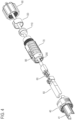
- FIG. 3 illustrates an example of a plug connector according to the embodiment of the present invention.
- FIGs. 4 and 5 illustrate a plug connector 100 of FIG. 3 in a manner to explode the plug connector 100 into components.
- FIG. 3 omits illustration of an optical cable to which the plug connector 100 is attached.
- the plug connector 100 is configured to include a barrel assembly 40, a photoelectric conversion module 50, an optical connector 60, an end bell 70, a locking member 80, a ground nut 90, a bushing 110, and a ring 120 as illustrated in FIGs. 4 and 5 in this example.
- 200 denotes an optical cable.
- the optical connector 60 is attached to a terminal of the optical cable 200.
- the optical connector 60 is an LC2-core connector in this example.
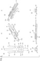
- the barrel assembly 40 is a portion that is fitted to and connected with a mating receptacle connector. As illustrated in FIG. 6 , the barrel assembly 40 includes a barrel 41, a lock ring 42, a slider 43, a plate spring 44, and a screw 45. A front end side of the barrel 41 is an insertion portion 41a that is inserted into a mating receptacle connector, and the insertion portion 41a has a C-shape section.
- the lock ring 42 and the slider 43 are attached around a cylindrical surface 41c which is formed by an outer circumferential surface of an attachment portion 41b on a rear end side of the barrel 41.
- An attachment hole 41d is formed to penetrate through the attachment portion 41b in a front and rear direction.
- the attachment hole 41d communicates with an internal space of the C shape of the insertion portion 41a.
- the plate spring 44 is arranged in the attachment hole 41d in a manner such that one end of the plate spring 44 is fixed on the barrel 41 by the screw 45.
- 46 and 47 in FIG. 6(d) denote O rings.
- the photoelectric conversion module 50 is an SFP module in this example.
- the photoelectric conversion module 50 is inserted into the attachment hole 41d of the barrel 41 so as to be accommodated and held by the barrel 41 as illustrated in FIG. 7 .
- the plate spring 44 that is arranged in the attachment hole 41d of the barrel 41 functions as a fixing means of the photoelectric conversion module 50.
- the end bell 70 which serves as an outer shell of the plug connector 100, has a cylindrical shape, and the locking member 80 is attached to the end bell 70 as illustrated in FIGs. 4 and 5 .
- an axial center of the end bell 70 is assumed to be a Z axis (see FIGs. 9 and 10 described later).
- the locking member 80 is attached to the end bell 70 in a manner to be movable in the Z-axis direction.
- FIG. 8 illustrates a detailed shape of the locking member 80.
- the locking member 80 is made of resin to be formed in one piece in this example.
- the locking member 80 includes a main trunk portion 81, a pair of spring pieces 82, a pair of extended pieces 83, and claws 84.
- the main trunk portion 81 elongates in the Z-axis direction.
- the spring pieces 82 are formed to be extended on respective sides of the main trunk portion 81 in the width direction so that a distance between the spring pieces 82 increases toward the rear side (backward in the Z-axis direction) to form a V shape.
- the extended pieces 83 are formed to be extended frontward (frontward in the Z-axis direction) on respective sides of the main trunk portion 81 in the width direction, and front ends of the extended pieces 83 are positioned on the rear side compared to the front end of the main trunk portion 81 (backward in the Z-axis direction).
- the claws 84 are formed on the pair of extended pieces 83 in a manner to protrude outward from each other.
- the pair of spring pieces 82 has an elastic restoring force against an external force that reduces their mutual distance.
- Each base end of the pair of spring pieces 82 and each base end of the pair of extended pieces 83 are coupled with and supported by a pair of arm portions 85, which are formed from the main trunk portion 81 in a manner to protrude mutually outward in this example.
- an operation portion 86 is provided so as to form a two-stage structure with the main trunk portion 81.
- a front end portion 81a of the main trunk portion 81 is shaped to have a step shift in the width direction, which forms a cutout 81b at the front end. Further, the front end portion 81a of the main trunk portion 81 is thicker than a portion following the front end portion 81a.
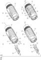
- FIGs. 9(a) and 9(b) illustrate a state in which the locking member 80 is attached to the end bell 70.
- FIGs. 9(c) and 9(d) are drawings corresponding to FIGs. 9(a) and 9(b) respectively, and provide partially-omitted illustration of the end bell 70 so as to describe details of the attachment.
- a concave groove 72 is formed on a circumferential wall 71 of the end bell 70 in a manner to be extended in a front and rear direction (Z-axis direction), as illustrated in FIG. 9(c) providing the partially-omitted illustration of the circumferential wall 71. That is, part of the circumferential wall 71 of the end bell 70 has the two-stage structure with the concave groove 72 interposed, the concave groove 72 forming a narrow gap.
- the rear end side of the concave groove 72 in the Z-axis direction is formed to be narrowed toward the rear side.
- the main trunk portion 81 and the pair of spring pieces 82 are inserted from the front end of the end bell 70 into the concave groove 72, and the locking member 80 is thus attached. Accordingly, the pair of spring pieces 82 are sandwiched between side walls 72a and 72b of the concave groove 72 from respective outer sides, as illustrated in FIG. 9(d) .
- the pair of spring pieces 82 has the elastic restoring force against an external force that reduces the mutual distance, as mentioned above. That is, when the ends of the pair of spring pieces 82 are pressed up to the position of a narrow portion 72c of the concave groove 72 in the attachment of the locking member 80 to the end bell 70, the elastic restoring force of the pair of spring pieces 82 urges the locking member 80 frontward (frontward in the Z-axis direction). However, the claws 84, which are formed on the pair of extended pieces 83 in a protruding manner, are caught by locking portions 73 formed on the end bell 70, thereby preventing the locking member 80 from coming off frontward in the Z-axis direction. In the state in which the locking member 80 is attached to the end bell 70, the front end side of the main trunk portion 81 and the operation portion 86 are exposed as illustrated in FIG. 9(b) .
- FIG. 10 illustrates a state in which the locking member 80 is retained and attached to the end bell 70 as described above.
- FIG. 10(d) provides partially-omitted illustration of the circumferential wall 71 of the end bell 70 as is the case with FIG. 9(d) , and illustrates a state in which a pair of claws 84 are caught by the locking portions 73 of the end bell 70 to prevent the locking member 80 from coming off.
- FIG. 10(c) illustrates a state in which part of the circumferential wall 71 of the end bell 70 has a two-stage structure with the concave groove 72, into which the locking member 80 is inserted, sandwiched.
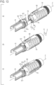
- FIGs. 11(a) to 11(c) and FIGs. 12(a) and 12(b) show an outline of the method for assembling the plug connector 100 in order.
- FIGs. 13 to 15 only show the barrel 41, to which the O rings 46 and 47 are attached, and the end bell 70, to which the locking member 80 is attached, and omit illustration of other components.
- the Z-axis-direction locking mechanism is composed of a first convex portion, which is provided on one of the cylindrical surface 41c of the barrel 41 and the inner circumferential surface on the front end side of the end bell 70, and a concave portion, which is provided on the other.
- the concave portion is composed of a Z-axis-direction groove guiding the first convex portion and a circumferential-direction groove which is formed to be extended from an inner end of the Z-axis direction-groove in the circumferential direction.
- first convex portions 41e are provided at three locations at equal angular intervals in the circumferential direction on the cylindrical surface 41c of the barrel 41
- concave portions 75 are provided at three locations on the inner circumferential surface on the front end side of the end bell 70 corresponding to the first convex portions 41e, in this example.
- 75a denotes a Z-axis-direction groove of the concave portion 75
- 75b denotes a circumferential-direction groove of the concave portion 75.
- the embodiment of the present invention is not limited to this example, and may employ a configuration in which the first convex portions are provided on the inner circumferential surface on the front end side of the end bell 70 and the concave portion is provided on the cylindrical surface 41c of the barrel 41 and which performs the same function.
- the rotation locking mechanism about the Z axis is composed of a second convex portion 41f and the locking member 80, as illustrated in FIGs. 13 and 14 .
- the second convex portion 41f is provided on the cylindrical surface 41c of the barrel 41, and the locking member 80 is attached to the end bell 70 in a manner to be movable in the Z-axis direction as described above.
- the first convex portion 41e which is provided on the cylindrical surface 41c of the barrel 41, is inserted into the Z-axis-direction groove 75a of the concave portion 75, which is provided on the inner circumferential surface of the end bell 70.
- the front end of the main trunk portion 81 is abutted on the second convex portion 41f, which is provided on the cylindrical surface 41c, thereby pushing the locking member 80 backward in the Z-axis direction as illustrated in FIGs. 13(b) and 14(b) .
- This generates a state in which the ends of the pair of spring pieces 82 of the locking member 80 are positioned in the narrow portion 72c of the concave groove 72 of the end bell 70.
- FIG. 15(c) illustrates a state in which the first convex portion 41e is positioned in the circumferential-direction groove 75b and the barrel 41 and the end bell 70 are thus locked in the Z-axis direction.
- the front end of the main trunk portion 81 of the locking member 80 is disengaged from the second convex portion 41f and the abutting on the second convex portion 41f is released.
- the locking member 80 is urged by the elastic restoring force of the pair of spring pieces 82 so as to move frontward in the Z-axis direction as illustrated in FIGs. 13(c) and 14(c) .
- the second convex portion 41f is positioned in the cutout 81b, which is on the front end of the main trunk portion 81, in this example, and the rotation of the end bell 70 in the reverse direction to the direction illustrated by the arrow a is blocked when the front end portion 81a of the main trunk portion 81 is abutted on the second convex portion 41f in the rotation direction. That is, the rotation is locked and the fitting between the end bell 70 and the barrel 41 is thus completed.
- the end bell 70 can be detached from the fitting completion state between the end bell 70 and the barrel 41 to separate the end bell 70 and the barrel 41 from each other in a manner such that the operation portion 86 of the locking member 80 is operated to move the locking member 80 backward against an urging force of the pair of spring pieces 82, and the end bell 70 is rotated in the reverse direction to the direction illustrated by the arrow a while releasing the abutting between the front end portion 81a of the main trunk portion 81 and the second convex portion 41f in the rotation direction so as to locate the end bell 70 on a predetermined position and pull out the end bell 70 from the barrel 41.
- the Z-axis direction locking and the rotation locking are performed by fitting the end bell 70 to the cylindrical surface 41c of the barrel 41 and rotating the end bell 70, being able to easily assemble the barrel 41 and the end bell 70. Further, the end bell 70 can be easily detached from the barrel 41 by moving the locking member 80 backward and rotating the end bell 70 in the reverse direction to that in the locking. As a result, if there is a need for replacing the photoelectric conversion module 50 accommodated in the barrel 41, the replacement work can be easily performed.
- the optical cable 200 is fixed to the end bell 70 with the ring 120 and the bushing 110, which are sandwiched between the ground nut 90 (rear end component) attached from the rear side and fastened to the rear end of the end bell 70 and the end bell 70, interposed therebetween. Therefore, when locking is released to pull out the end bell 70 from the barrel 41, a tensile force acts on the optical cable 200 along with the pulling out of the end bell 70.
- a tensile force acts on the optical connector 60, which is attached to the optical cable 200 and is connected with the photoelectric conversion module 50, sometimes resulting in a damage of the optical connector 60 and the photoelectric conversion module 50 connected with the optical connector 60. Further, such a damage or poor connection between the optical connector 60 and the photoelectric conversion module 50 can also occur when the end bell 70 is unlocked and pulled out of the barrel 41 for some reason.
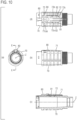
- a configuration may be employed in which locking cannot be released unless the ground nut 90 is removed. This configuration will be described below with reference to FIG. 16 .
- a rear end 81c of the main trunk portion 81 is positioned to slightly protrude from the end bell 70 and overlap with the male screw portion 74.
- the rear end 81c is positioned not to overlap with the male screw portion 74 as illustrated in FIG. 16(a) .
Landscapes
- Physics & Mathematics (AREA)
- General Physics & Mathematics (AREA)
- Optics & Photonics (AREA)
- Optical Couplings Of Light Guides (AREA)
- Mechanical Coupling Of Light Guides (AREA)
- Details Of Connecting Devices For Male And Female Coupling (AREA)
Applications Claiming Priority (1)
| Application Number | Priority Date | Filing Date | Title |
|---|---|---|---|
| JP2023012451A JP2024108209A (ja) | 2023-01-31 | 2023-01-31 | プラグコネクタ |
Publications (2)
| Publication Number | Publication Date |
|---|---|
| EP4411443A1 true EP4411443A1 (de) | 2024-08-07 |
| EP4411443B1 EP4411443B1 (de) | 2025-10-29 |
Family
ID=89119147
Family Applications (1)
| Application Number | Title | Priority Date | Filing Date |
|---|---|---|---|
| EP23214260.4A Active EP4411443B1 (de) | 2023-01-31 | 2023-12-05 | Steckverbindung |
Country Status (4)
| Country | Link |
|---|---|
| US (1) | US12546961B2 (de) |
| EP (1) | EP4411443B1 (de) |
| JP (1) | JP2024108209A (de) |
| CN (1) | CN118426117A (de) |
Families Citing this family (2)
| Publication number | Priority date | Publication date | Assignee | Title |
|---|---|---|---|---|
| JP1742935S (ja) * | 2022-08-05 | 2023-04-26 | 光コネクタ | |
| JP2024108209A (ja) * | 2023-01-31 | 2024-08-13 | 日本航空電子工業株式会社 | プラグコネクタ |
Citations (5)
| Publication number | Priority date | Publication date | Assignee | Title |
|---|---|---|---|---|
| US20100104355A1 (en) * | 2008-10-28 | 2010-04-29 | Japan Aviation Electronics Industry, Limited | Adapter unit |
| JP2018040820A (ja) * | 2015-02-23 | 2018-03-15 | Seiオプティフロンティア株式会社 | 光コネクタプラグ、光コネクタ用レセプタクル、および光コネクタ接続構造 |
| US20190049678A1 (en) * | 2017-08-08 | 2019-02-14 | Japan Aviation Electronics Industry, Limited | Connector device and plug connector |
| EP3514590A1 (de) * | 2016-09-30 | 2019-07-24 | Huawei Technologies Co., Ltd. | Glasfaserunteranordnung, glasfaseradapter und glasfaserstecker |
| EP3904930A1 (de) * | 2020-04-28 | 2021-11-03 | Japan Aviation Electronics Industry, Ltd. | Verfahren zur herstellung eines steckers mit optischem verbinder und stecker mit optischem verbinder |
Family Cites Families (26)
| Publication number | Priority date | Publication date | Assignee | Title |
|---|---|---|---|---|
| US7264402B2 (en) * | 2005-03-10 | 2007-09-04 | Corning Cable Systems Llc | Multi-fiber optic receptacle and plug assembly |
| JP5371460B2 (ja) * | 2009-01-29 | 2013-12-18 | モレックス インコーポレイテド | 光コネクタ |
| FR2944361B1 (fr) * | 2009-04-08 | 2011-05-13 | Radiall Sa | Systeme d'interconnexion |
| US8272790B2 (en) * | 2009-11-24 | 2012-09-25 | Amphenol Fiber Optics | Outdoor transceiver connector |
| EP2355283A1 (de) * | 2010-01-29 | 2011-08-10 | Tyco Electronics Raychem BVBA | Kabelabdichtungsvorrichtung, Kabelabschluss und Befestigungsvorrichtung |
| WO2012167102A1 (en) * | 2011-06-03 | 2012-12-06 | Foro Energy Inc. | Rugged passively cooled high power laser fiber optic connectors and methods of use |
| JP5826594B2 (ja) * | 2011-10-28 | 2015-12-02 | 日本航空電子工業株式会社 | コネクタ |
| JP5890273B2 (ja) * | 2012-07-27 | 2016-03-22 | 日本航空電子工業株式会社 | プラグ及び光コネクタ接続体 |
| EP3022599A1 (de) * | 2013-07-16 | 2016-05-25 | 3M Innovative Properties Company | Telekommunikationsgehäuse für externe verbindungen |
| EP3021145B1 (de) * | 2014-11-14 | 2020-04-29 | Corning Optical Communications LLC | Optischer Adapter zur Montage an einem Behälter zum optischen Verbinden anschlussfertiger optischer Kabel |
| US9755382B2 (en) * | 2015-03-13 | 2017-09-05 | Senko Advanced Components, Inc. | Connector system with interchangeable connector modules for optical fibers, electrical conductors, or both |
| JP6133390B1 (ja) * | 2015-12-15 | 2017-05-24 | 日本航空電子工業株式会社 | コネクタ内蔵プラグ |
| TWM531675U (zh) * | 2016-03-31 | 2016-11-01 | Advanced Connectek Inc | 防水襯套連接器組件、防水襯套插座連接器以及防水襯套插頭連接器 |
| FR3053846B1 (fr) * | 2016-07-07 | 2020-08-21 | Radiall Sa | Fiche de connexion a une embase de panneau de boitier d'equipement electronique, munie de moyens d'auto-alignement |
| JP6776097B2 (ja) * | 2016-11-11 | 2020-10-28 | 日本航空電子工業株式会社 | コネクタ |
| CN111065946B (zh) * | 2017-06-28 | 2023-08-18 | 康宁研究与开发公司 | 具有键接连接端口和固定特征的多端口件和其他装置及其制造方法 |
| US11300746B2 (en) * | 2017-06-28 | 2022-04-12 | Corning Research & Development Corporation | Fiber optic port module inserts, assemblies and methods of making the same |
| WO2019173350A1 (en) * | 2018-03-06 | 2019-09-12 | Commscope Technologies Llc | Modular hardened optical fiber connector and assembly method thereof |
| JP6605660B1 (ja) * | 2018-06-19 | 2019-11-13 | 日本航空電子工業株式会社 | コネクタ装置、コネクタ及び相手側コネクタ |
| JP6619500B1 (ja) * | 2018-12-25 | 2019-12-11 | 日本航空電子工業株式会社 | コネクタ装置 |
| CN111384702B (zh) * | 2018-12-28 | 2021-12-03 | 泰科电子(上海)有限公司 | 线缆固定装置、线缆连接器和电器设备 |
| JP7249195B2 (ja) * | 2019-04-04 | 2023-03-30 | 日本航空電子工業株式会社 | レセプタクル |
| JP6792673B1 (ja) * | 2019-06-25 | 2020-11-25 | 日本航空電子工業株式会社 | プラグコネクタ |
| US11585994B2 (en) * | 2020-05-20 | 2023-02-21 | Commscope Technologies Llc | Active optical cable assemblies |
| CN215119418U (zh) * | 2021-06-18 | 2021-12-10 | 泰科电子(上海)有限公司 | 连接器和连接器组件 |
| JP2024108209A (ja) * | 2023-01-31 | 2024-08-13 | 日本航空電子工業株式会社 | プラグコネクタ |
-
2023
- 2023-01-31 JP JP2023012451A patent/JP2024108209A/ja active Pending
- 2023-12-05 EP EP23214260.4A patent/EP4411443B1/de active Active
- 2023-12-12 CN CN202311702874.7A patent/CN118426117A/zh active Pending
- 2023-12-14 US US18/539,689 patent/US12546961B2/en active Active
Patent Citations (6)
| Publication number | Priority date | Publication date | Assignee | Title |
|---|---|---|---|---|
| US20100104355A1 (en) * | 2008-10-28 | 2010-04-29 | Japan Aviation Electronics Industry, Limited | Adapter unit |
| JP2018040820A (ja) * | 2015-02-23 | 2018-03-15 | Seiオプティフロンティア株式会社 | 光コネクタプラグ、光コネクタ用レセプタクル、および光コネクタ接続構造 |
| EP3514590A1 (de) * | 2016-09-30 | 2019-07-24 | Huawei Technologies Co., Ltd. | Glasfaserunteranordnung, glasfaseradapter und glasfaserstecker |
| US20190049678A1 (en) * | 2017-08-08 | 2019-02-14 | Japan Aviation Electronics Industry, Limited | Connector device and plug connector |
| JP2019032432A (ja) | 2017-08-08 | 2019-02-28 | 日本航空電子工業株式会社 | コネクタ装置及びプラグコネクタ |
| EP3904930A1 (de) * | 2020-04-28 | 2021-11-03 | Japan Aviation Electronics Industry, Ltd. | Verfahren zur herstellung eines steckers mit optischem verbinder und stecker mit optischem verbinder |
Also Published As
| Publication number | Publication date |
|---|---|
| JP2024108209A (ja) | 2024-08-13 |
| CN118426117A (zh) | 2024-08-02 |
| US20240255715A1 (en) | 2024-08-01 |
| US12546961B2 (en) | 2026-02-10 |
| EP4411443B1 (de) | 2025-10-29 |
Similar Documents
| Publication | Publication Date | Title |
|---|---|---|
| US12546961B2 (en) | Plug connector | |
| JP6318008B2 (ja) | 光コネクタ | |
| KR101111452B1 (ko) | 광커넥터 내장 플러그 | |
| EP0997757B1 (de) | Zylindrischer Stecker mit einem rechteckigen faseroptischen Steckerstift | |
| EP2253977B1 (de) | Wasserfester Steckverbinder und wasserfeste Vorrichtung, die diesen Steckverbinder einsetzt | |
| US7011544B1 (en) | Multiphase connector | |
| EP3955397B1 (de) | Steckverbinder | |
| JP2660440B2 (ja) | 光コネクタ組立体 | |
| US8485736B2 (en) | Optical connector | |
| EP3211466B1 (de) | Steckerteil einer verbindungseinheit | |
| EP3677938B1 (de) | Optischer steckverbinder und verfahren zum anschluss eines optischen steckverbinders | |
| JP5398560B2 (ja) | 光コネクタ及びその組立方法 | |
| EP0875959B1 (de) | Steckverbindungssystem | |
| EP1180702B1 (de) | Schutzvorrichtung an einem faseroptischen Steckverbinder | |
| WO2018042779A1 (ja) | 光コネクタ組立体 | |
| EP3739367B1 (de) | Verbinder | |
| WO2019159431A1 (ja) | 光コネクタ及び光コネクタの接続方法 | |
| WO2023058634A1 (ja) | 光-電気複合コネクタ | |
| US6893161B2 (en) | Optical connector device | |
| US7416348B2 (en) | Optical connector excellent in assemblability and dimensional accuracy | |
| JP4203442B2 (ja) | マウントバリア装置 | |
| WO2025227428A1 (zh) | 一种光电复合连接器 | |
| CN120891593A (zh) | 一种光纤预端接转接器 | |
| CN119322395A (zh) | 一种室外光纤连接器、光纤转接器和光纤链路系统 | |
| CN117289404A (zh) | 光连接器 |
Legal Events
| Date | Code | Title | Description |
|---|---|---|---|
| PUAI | Public reference made under article 153(3) epc to a published international application that has entered the european phase |
Free format text: ORIGINAL CODE: 0009012 |
|
| STAA | Information on the status of an ep patent application or granted ep patent |
Free format text: STATUS: THE APPLICATION HAS BEEN PUBLISHED |
|
| AK | Designated contracting states |
Kind code of ref document: A1 Designated state(s): AL AT BE BG CH CY CZ DE DK EE ES FI FR GB GR HR HU IE IS IT LI LT LU LV MC ME MK MT NL NO PL PT RO RS SE SI SK SM TR |
|
| STAA | Information on the status of an ep patent application or granted ep patent |
Free format text: STATUS: REQUEST FOR EXAMINATION WAS MADE |
|
| 17P | Request for examination filed |
Effective date: 20250207 |
|
| GRAP | Despatch of communication of intention to grant a patent |
Free format text: ORIGINAL CODE: EPIDOSNIGR1 |
|
| STAA | Information on the status of an ep patent application or granted ep patent |
Free format text: STATUS: GRANT OF PATENT IS INTENDED |
|
| INTG | Intention to grant announced |
Effective date: 20250528 |
|
| GRAS | Grant fee paid |
Free format text: ORIGINAL CODE: EPIDOSNIGR3 |
|
| GRAA | (expected) grant |
Free format text: ORIGINAL CODE: 0009210 |
|
| STAA | Information on the status of an ep patent application or granted ep patent |
Free format text: STATUS: THE PATENT HAS BEEN GRANTED |
|
| AK | Designated contracting states |
Kind code of ref document: B1 Designated state(s): AL AT BE BG CH CY CZ DE DK EE ES FI FR GB GR HR HU IE IS IT LI LT LU LV MC ME MK MT NL NO PL PT RO RS SE SI SK SM TR |
|
| REG | Reference to a national code |
Ref country code: CH Ref legal event code: F10 Free format text: ST27 STATUS EVENT CODE: U-0-0-F10-F00 (AS PROVIDED BY THE NATIONAL OFFICE) Effective date: 20251029 Ref country code: GB Ref legal event code: FG4D |
|
| REG | Reference to a national code |
Ref country code: DE Ref legal event code: R096 Ref document number: 602023008021 Country of ref document: DE |
|
| REG | Reference to a national code |
Ref country code: IE Ref legal event code: FG4D |
|
| PGFP | Annual fee paid to national office [announced via postgrant information from national office to epo] |
Ref country code: AT Payment date: 20260113 Year of fee payment: 3 |
|
| PGFP | Annual fee paid to national office [announced via postgrant information from national office to epo] |
Ref country code: FR Payment date: 20251217 Year of fee payment: 3 |
|
| REG | Reference to a national code |
Ref country code: NL Ref legal event code: MP Effective date: 20251029 |
|
| PG25 | Lapsed in a contracting state [announced via postgrant information from national office to epo] |
Ref country code: ES Free format text: LAPSE BECAUSE OF FAILURE TO SUBMIT A TRANSLATION OF THE DESCRIPTION OR TO PAY THE FEE WITHIN THE PRESCRIBED TIME-LIMIT Effective date: 20251029 |
|
| REG | Reference to a national code |
Ref country code: LT Ref legal event code: MG9D |
|
| PG25 | Lapsed in a contracting state [announced via postgrant information from national office to epo] |
Ref country code: NO Free format text: LAPSE BECAUSE OF FAILURE TO SUBMIT A TRANSLATION OF THE DESCRIPTION OR TO PAY THE FEE WITHIN THE PRESCRIBED TIME-LIMIT Effective date: 20260129 |
|
| PGFP | Annual fee paid to national office [announced via postgrant information from national office to epo] |
Ref country code: DE Payment date: 20251231 Year of fee payment: 3 |
|
| PG25 | Lapsed in a contracting state [announced via postgrant information from national office to epo] |
Ref country code: FI Free format text: LAPSE BECAUSE OF FAILURE TO SUBMIT A TRANSLATION OF THE DESCRIPTION OR TO PAY THE FEE WITHIN THE PRESCRIBED TIME-LIMIT Effective date: 20251029 Ref country code: AT Free format text: LAPSE BECAUSE OF FAILURE TO SUBMIT A TRANSLATION OF THE DESCRIPTION OR TO PAY THE FEE WITHIN THE PRESCRIBED TIME-LIMIT Effective date: 20251029 Ref country code: HR Free format text: LAPSE BECAUSE OF FAILURE TO SUBMIT A TRANSLATION OF THE DESCRIPTION OR TO PAY THE FEE WITHIN THE PRESCRIBED TIME-LIMIT Effective date: 20251029 |
|
| PGFP | Annual fee paid to national office [announced via postgrant information from national office to epo] |
Ref country code: IT Payment date: 20251231 Year of fee payment: 3 |
|
| REG | Reference to a national code |
Ref country code: AT Ref legal event code: MK05 Ref document number: 1852176 Country of ref document: AT Kind code of ref document: T Effective date: 20251029 |
|
| PG25 | Lapsed in a contracting state [announced via postgrant information from national office to epo] |
Ref country code: NL Free format text: LAPSE BECAUSE OF FAILURE TO SUBMIT A TRANSLATION OF THE DESCRIPTION OR TO PAY THE FEE WITHIN THE PRESCRIBED TIME-LIMIT Effective date: 20251029 |
|
| PG25 | Lapsed in a contracting state [announced via postgrant information from national office to epo] |
Ref country code: RS Free format text: LAPSE BECAUSE OF FAILURE TO SUBMIT A TRANSLATION OF THE DESCRIPTION OR TO PAY THE FEE WITHIN THE PRESCRIBED TIME-LIMIT Effective date: 20260129 |
|
| PG25 | Lapsed in a contracting state [announced via postgrant information from national office to epo] |
Ref country code: IS Free format text: LAPSE BECAUSE OF FAILURE TO SUBMIT A TRANSLATION OF THE DESCRIPTION OR TO PAY THE FEE WITHIN THE PRESCRIBED TIME-LIMIT Effective date: 20260228 |
|
| PG25 | Lapsed in a contracting state [announced via postgrant information from national office to epo] |
Ref country code: PT Free format text: LAPSE BECAUSE OF FAILURE TO SUBMIT A TRANSLATION OF THE DESCRIPTION OR TO PAY THE FEE WITHIN THE PRESCRIBED TIME-LIMIT Effective date: 20260302 |
|
| PG25 | Lapsed in a contracting state [announced via postgrant information from national office to epo] |
Ref country code: PL Free format text: LAPSE BECAUSE OF FAILURE TO SUBMIT A TRANSLATION OF THE DESCRIPTION OR TO PAY THE FEE WITHIN THE PRESCRIBED TIME-LIMIT Effective date: 20251029 |
|
| PG25 | Lapsed in a contracting state [announced via postgrant information from national office to epo] |
Ref country code: LV Free format text: LAPSE BECAUSE OF FAILURE TO SUBMIT A TRANSLATION OF THE DESCRIPTION OR TO PAY THE FEE WITHIN THE PRESCRIBED TIME-LIMIT Effective date: 20251029 |
|
| PG25 | Lapsed in a contracting state [announced via postgrant information from national office to epo] |
Ref country code: BG Free format text: LAPSE BECAUSE OF FAILURE TO SUBMIT A TRANSLATION OF THE DESCRIPTION OR TO PAY THE FEE WITHIN THE PRESCRIBED TIME-LIMIT Effective date: 20251029 |