EP4411693A1 - Dispositif d'aide au stationnement - Google Patents
Dispositif d'aide au stationnement Download PDFInfo
- Publication number
- EP4411693A1 EP4411693A1 EP22876105.2A EP22876105A EP4411693A1 EP 4411693 A1 EP4411693 A1 EP 4411693A1 EP 22876105 A EP22876105 A EP 22876105A EP 4411693 A1 EP4411693 A1 EP 4411693A1
- Authority
- EP
- European Patent Office
- Prior art keywords
- target position
- movement target
- vehicle
- parking assistance
- correction
- Prior art date
- Legal status (The legal status is an assumption and is not a legal conclusion. Google has not performed a legal analysis and makes no representation as to the accuracy of the status listed.)
- Granted
Links
Images


Classifications
-
- B—PERFORMING OPERATIONS; TRANSPORTING
- B62—LAND VEHICLES FOR TRAVELLING OTHERWISE THAN ON RAILS
- B62D—MOTOR VEHICLES; TRAILERS
- B62D15/00—Steering not otherwise provided for
- B62D15/02—Steering position indicators ; Steering position determination; Steering aids
- B62D15/027—Parking aids, e.g. instruction means
- B62D15/0285—Parking performed automatically
-
- B—PERFORMING OPERATIONS; TRANSPORTING
- B60—VEHICLES IN GENERAL
- B60W—CONJOINT CONTROL OF VEHICLE SUB-UNITS OF DIFFERENT TYPE OR DIFFERENT FUNCTION; CONTROL SYSTEMS SPECIALLY ADAPTED FOR HYBRID VEHICLES; ROAD VEHICLE DRIVE CONTROL SYSTEMS FOR PURPOSES NOT RELATED TO THE CONTROL OF A PARTICULAR SUB-UNIT
- B60W30/00—Purposes of road vehicle drive control systems not related to the control of a particular sub-unit, e.g. of systems using conjoint control of vehicle sub-units
- B60W30/06—Automatic manoeuvring for parking
-
- B—PERFORMING OPERATIONS; TRANSPORTING
- B60—VEHICLES IN GENERAL
- B60W—CONJOINT CONTROL OF VEHICLE SUB-UNITS OF DIFFERENT TYPE OR DIFFERENT FUNCTION; CONTROL SYSTEMS SPECIALLY ADAPTED FOR HYBRID VEHICLES; ROAD VEHICLE DRIVE CONTROL SYSTEMS FOR PURPOSES NOT RELATED TO THE CONTROL OF A PARTICULAR SUB-UNIT
- B60W40/00—Estimation or calculation of non-directly measurable driving parameters for road vehicle drive control systems not related to the control of a particular sub unit, e.g. by using mathematical models
- B60W40/02—Estimation or calculation of non-directly measurable driving parameters for road vehicle drive control systems not related to the control of a particular sub unit, e.g. by using mathematical models related to ambient conditions
-
- B—PERFORMING OPERATIONS; TRANSPORTING
- B60—VEHICLES IN GENERAL
- B60W—CONJOINT CONTROL OF VEHICLE SUB-UNITS OF DIFFERENT TYPE OR DIFFERENT FUNCTION; CONTROL SYSTEMS SPECIALLY ADAPTED FOR HYBRID VEHICLES; ROAD VEHICLE DRIVE CONTROL SYSTEMS FOR PURPOSES NOT RELATED TO THE CONTROL OF A PARTICULAR SUB-UNIT
- B60W60/00—Drive control systems specially adapted for autonomous road vehicles
-
- G—PHYSICS
- G01—MEASURING; TESTING
- G01C—MEASURING DISTANCES, LEVELS OR BEARINGS; SURVEYING; NAVIGATION; GYROSCOPIC INSTRUMENTS; PHOTOGRAMMETRY OR VIDEOGRAMMETRY
- G01C21/00—Navigation; Navigational instruments not provided for in groups G01C1/00 - G01C19/00
- G01C21/26—Navigation; Navigational instruments not provided for in groups G01C1/00 - G01C19/00 specially adapted for navigation in a road network
-
- G—PHYSICS
- G08—SIGNALLING
- G08G—TRAFFIC CONTROL SYSTEMS
- G08G1/00—Traffic control systems for road vehicles
- G08G1/16—Anti-collision systems
Definitions
- An embodiment of the present invention relates to a parking assistance device.
- a parking assistance device that assists a vehicle parking operation by a driver in a parking lot or the like is conventionally known.
- the parking assistance device sets a movement target position of the vehicle in a parking space defined by dividing lines (e.g. a pair of white lines) included in a captured image, and guides the vehicle to the movement target position.
- Patent Literature 1 JP 2015-74254 A
- Errors in the results of recognition of dividing lines cause, for example, cutting of the wheel when the vehicle is guided to the movement target position, reducing the accuracy of vehicle guidance, which is not preferable.
- adding a vehicle height sensor or the like can provide an improvement but has a problem of increased cost.
- the present invention provides a parking assistance device that allows a vehicle to be guided to a parking space with high accuracy even when there are errors in the results of recognition of dividing lines using a captured image, without adding a physical configuration.
- a parking assistance device of an embodiment of the present invention includes, for example, an image acquisition unit that acquires a captured image from an imaging unit that images surrounding circumstances of a vehicle, a setting unit that sets, at the start of parking assistance, a reference movement target position of the vehicle in a parking space defined by a pair of spaced dividing lines included in the captured image, and sets, after the start of the parking assistance, a movement target position of the vehicle in the parking space defined by the pair of dividing lines included in the captured image, at predetermined control periods, a correction unit that corrects the movement target position, based on the reference movement target position, a position acquisition unit that acquires the current position of the vehicle, and a guidance control unit that performs control to guide the vehicle to the corrected movement target position, based on the corrected movement target position and the current position.
- This configuration corrects the movement target position after the start of the parking assistance, using the reference movement target position set at the start of the parking assistance, and thus can guide the vehicle into the parking space with high accuracy even when there are errors in the results of recognition of the dividing lines using the captured image, without adding a physical configuration.
- the shorter the distance from the vehicle to the movement target position the smaller the correction unit may make the amount of correction by which to correct the movement target position.
- This configuration can avoid a situation in which the movement target position is corrected too much by a factor other than changes in the position and angle of a camera (such as a slope or a step on a road).
- the correction unit may perform correction to bring the movement target position closer to the reference movement target position when the movement target position is farther from the turning center of the turning path than the reference movement target position, and may not correct the movement target position when the movement target position is closer to the turning center of the turning path than the reference movement target position.
- the movement target position when the movement target position is closer to the turning center of the turning path than the reference movement target position, in which the need for correction is low, the movement target position is not corrected. This can avoid destabilization of vehicle guidance that may occur when the movement target position is corrected.
- the correction unit may maintain the amount of correction without increasing the amount of correction.
- This configuration can avoid a situation in which the vehicle swings in the side-to-side directions during guidance.
- the correction unit may reset the amount of correction by which to correct the movement target position.
- This configuration can achieve an appropriate response of resetting the amount of correction when a new dividing line has been recognized.
- the correction unit may finish the correction of the movement target position.
- This configuration can achieve an appropriate response of finishing the correction in response to the fact that the angle becomes equal to or less than the predetermined angle, that is, the fact that the possibility of occurrence of cutting of the wheel during vehicle guidance has disappeared.
- the setting unit may recognize the start of the parking assistance, based on at least one of the fact that a shift operation part has been in a predetermined position, and the fact that a parking assistance start operation has been performed by a user.
- This configuration allows the start of parking assistance to be recognized by a specific trigger such as the fact that the shift operation part has been in the predetermined position or the fact that the parking assistance start operation has been performed by the user.
- the correction unit may correct the movement target position to the reference movement target position itself, or correct the movement target position to bring the movement target position closer to the reference movement target position.
- This configuration allows more specific correction such as correcting the movement target position to the reference movement target position itself or bringing the movement target position closer to the reference movement target position.
- an exemplary embodiment of the present invention is disclosed.
- a configuration of the embodiment described below and functions, results, and effects brought by the configuration are examples.
- the present invention can be implemented by a configuration other than that disclosed in the following embodiment, and can obtain at least one of various effects based on a basic configuration and derivative effects.
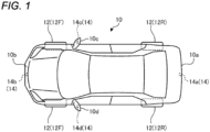
- FIG. 1 is a schematic plan view illustrating an example of a vehicle 10 that can be equipped with a parking assistance device of the embodiment.
- the vehicle 10 may be, for example, an automobile with an internal combustion engine (engine, not shown) as a drive source (an internal combustion vehicle), an automobile with an electric motor (motor, not shown) as a drive source (an electric vehicle, a fuel cell vehicle, or the like), or an automobile with both of them as drive sources (a hybrid vehicle).
- the vehicle 10 can be equipped with various transmissions, and can be equipped with various devices (systems, parts, etc.) necessary for driving the internal combustion engine or the electric motor.
- the type, number, layout, etc. of devices related to the drive of wheels 12 (front wheels 12F and rear wheels 12R) in the vehicle 10 can be set variously.
- the vehicle 10 is provided, for example, with four imaging units 14a to 14d as a plurality of imaging units 14 (hereinafter, also referred to as "cameras").
- the imaging units 14 are, for example, digital cameras each incorporating an imaging element such as a charge-coupled device (CCD) or a CMOS image sensor (CIS).
- the imaging units 14 can output moving image data (captured image data) at a predetermined frame rate.
- Each of the imaging units 14 includes a wide-angle lens or a fisheye lens, and can image a range of, for example, 140° to 220° in the horizontal direction.
- the optical axes of the imaging units 14 may be set obliquely downward.
- the imaging units 14 successively capture images of the surrounding environment outside the vehicle 10, including the road surface on which the vehicle 10 can move, marks provided to the road surface (including dividing lines indicating parking spaces, lane separation lines, arrows, etc.), and objects (such as pedestrians and vehicles as obstacles), and output the images as captured image data.
- the imaging units 14 are provided on outer peripheral portions of the vehicle 10.
- the imaging unit 14a is provided, for example, at a substantially central end portion in the vehicle width direction on the rear side of the vehicle 10, that is, on the back side in the vehicle front-back direction, for example, at a position above a rear bumper 10a, and can image a rear area including a rear end portion of the vehicle 10 (e.g. the rear bumper 10a).
- the imaging unit 14b is provided, for example, at a substantially central end portion in the vehicle width direction on the front side of the vehicle 10, that is, on the front side in the vehicle front-back direction, for example, at a front bumper 10b, a front grille, or the like, and can capture front images including a front end portion of the vehicle 10 (e.g. the front bumper 10b).
- the imaging unit 14c is provided, for example, at a right end portion of the vehicle 10, for example, at a right door mirror 10c, and can capture right side images including an area centered on the right side of the vehicle 10 (e.g. an area from the right front to the right rear).
- the imaging unit 14d is provided, for example, at a left end portion of the vehicle 10, for example, at a left door mirror 10d, and can capture left side images including an area centered on the left side of the vehicle 10 (e.g. an area from the left front to the left rear).
- the parking assistance device of the present embodiment can recognize (detect) dividing lines or the like by performing arithmetic processing and image processing, based on captured image data (images) obtained by the plurality of imaging units 14. By the recognition of dividing lines, the parking assistance device can perform a search for a parking space for parking the vehicle 10, the setting of a movement target position to use when guiding the vehicle 10 into the parking space, the estimation of the current position of the vehicle 10, the calculation of a movement path for guiding the vehicle 10 to the movement target position, etc.
- the parking assistance device can generate images with a wider viewing angle, and generate virtual images in which the vehicle 10 is viewed from above, the front, the side, etc. (overhead images (plane images), side view images, front view images, etc.).
- FIG. 2 is an exemplary block diagram of a configuration of a parking assistance system 100 including the parking assistance device of the embodiment.
- a display device 16 and an audio output device 18 are provided in the vehicle interior of the vehicle 10.
- the display device 16 is, for example, a liquid-crystal display (LCD), an organic electroluminescent display (OELD), or the like.
- the audio output device 18 is, for example, a speaker.
- the display device 16 is covered, for example, with a transparent operation input part 20 such as a touch panel.
- An occupant e.g., a driver
- the occupant can visually recognize an image displayed on a display screen of the display device 16 via the operation input part 20.
- the occupant can perform operation input by operating, for example, touching, pushing, or moving the operation input part 20 with a finger or the like at a position corresponding to an image displayed on the display screen of the display device 16.
- the display device 16, the audio output device 18, the operation input part 20, and others are provided, for example, in a monitor device 22 located at a central portion of the dashboard of the vehicle 10 in the vehicle width direction, that is, the side-to-side direction.
- the monitor device 22 can include an operation input part (not shown) such as a switch, a dial, a joystick, or a push button.
- the monitor device 22 can be shared, for example, with a navigation system and an audio system.
- the parking assistance system 100 (the parking assistance device) includes an electronic control unit (ECU) 24 in addition to the imaging units 14 (14a to 14d) and the monitor device 22.
- the ECU 24 and the monitor device 22 are electrically connected via an in-vehicle network 26 as an electric communication line.
- the in-vehicle network 26 is configured, for example, as a controller area network (CAN).
- the ECU 24 can control various systems by sending control signals through the in-vehicle network 26.
- a steering system 28, a steering angle sensor 30, a brake system 32, a drive system 34, an accelerator sensor 36, a shift sensor 38, wheel speed sensors 40, etc. are electrically connected via the in-vehicle network 26.
- the ECU 24 can control the steering system 28, the brake system 32, the drive system 34, etc. by sending control signals through the in-vehicle network 26.
- the ECU 24 can receive, via the in-vehicle network 26, the results of detection of a torque sensor 28a, a brake sensor 32a, the steering angle sensor 30, the accelerator sensor 36, the shift sensor 38, the wheel speed sensors 40, etc., an operation signal etc. from the operation input part 20 etc.
- the ECU 24 includes, for example, a central processing unit (CPU) 24a, read-only memory (ROM) 24b, random-access memory (RAM) 24c, a display control unit 24d, an audio control unit 24e, a solid-state drive (SSD, flash memory) 24f, etc.
- the CPU 24a can perform, for example, various types of arithmetic processing and control such as image processing related to an image to be displayed on the display device 16, in addition to the determination of a movement target position of the vehicle 10 when performing parking assistance, the estimation of the current position of the vehicle 10, the calculation of a movement distance, and the calculation of a target vehicle speed and a movement target position at each time.
- the CPU 24a can read a program installed and stored in a nonvolatile storage device such as the ROM 24b and perform arithmetic processing according to the program.
- the ROM 24b stores programs, parameters necessary for executing the programs, etc.
- the RAM 24c temporarily stores various data used in calculation in the CPU 24a.
- the display control unit 24d mainly performs, of the arithmetic processing in the ECU 24, image processing using image data obtained by the imaging units 14, the composition of image data to be displayed on the display device 16, etc.
- the audio control unit 24e mainly performs, of the arithmetic processing in the ECU 24, the processing of audio data to be output by the audio output device 18.
- the SSD 24f is a rewritable nonvolatile storage unit, and can store data even when power to the ECU 24 is turned off.
- the CPU 24a, the ROM 24b, the RAM 24c, etc. can be integrated in the same package.
- the ECU 24 may be configured to use another logical operation processor such as a digital signal processor (DSP), a logic circuit, or the like, instead of the CPU 24a.
- a hard disk drive (HDD) may be provided instead of the SSD 24f.
- the SSD 24f or the HDD may be provided separately from the ECU 24.
- the vehicle 10 is, for example, a four-wheeled automobile, and includes the two left and right front wheels 12F and the two left and right rear wheels 12R. All of the four wheels 12 can be configured to be steerable.
- the steering system 28 steers at least two of the wheels 12 of the vehicle 10.
- the steering system 28 includes the torque sensor 28a and an actuator 28b.
- the steering system 28 is electrically controlled by the ECU 24 or the like to operate the actuator 28b.
- the steering system 28 is, for example, an electric power steering system, a steer-by-wire (SBW) system, or the like.
- SBW steer-by-wire
- the steering system 28 adds torque, that is, assist torque to a steering part (e.g., a steering wheel) by the actuator 28b to supplement steering force, or steers the wheels 12 by the actuator 28b.
- the actuator 28b may steer one of the wheels 12 or may steer two or more of the wheels 12.
- the torque sensor 28a detects, for example, torque applied to the steering part by the driver.
- the steering angle sensor 30 is, for example, a sensor that detects the amount of steering of the steering part.
- the steering angle sensor 30 is configured using, for example, a Hall element or the like.
- the ECU 24 acquires the amount of steering of the steering part by the driver, the amount of steering of each wheel 12 at the time of automatic steering, etc. from the steering angle sensor 30, to perform various types of control.
- the steering angle sensor 30 detects the rotation angle of a rotating portion included in the steering part.
- the brake system 32 is, for example, an anti-lock brake system (ABS) that prevents brake locking, electronic stability control (ESC) that prevents the vehicle 10 from skidding at the time of cornering, an electric brake system that enhances braking force (performs brake assist), brake-by-wire (BBW), or the like.
- ABS anti-lock brake system
- ESC electronic stability control
- BBW brake-by-wire
- the brake system 32 applies braking force to the wheels 12 and thus to the vehicle 10 via an actuator 32b.
- the brake system 32 can perform various types of control by detecting a sign of brake locking, spinning of the wheels 12, skidding, etc. from the rotation difference between the left and right wheels 12 or the like.
- the brake sensor 32a is, for example, a sensor that detects the position of a movable portion of a braking operation part (e.g., a brake pedal).
- the drive system 34 is an internal combustion engine (engine) system or a motor system as a drive source.
- the drive system 34 controls the fuel injection amount and air-intake amount of the engine or controls the output value of the motor, according to the requested amount of operation (e.g. the amount of depression of the accelerator pedal) by the driver (user) detected by the accelerator sensor 36.
- the drive system 34 can control the output value of the engine or the motor in cooperation with the control of the steering system 28 and the brake system 32, according to the travel conditions of the vehicle 10. The same applies to a case where the vehicle 10 is traveling in an automatic travel mode.
- the accelerator sensor 36 is, for example, a sensor that detects the position of a movable portion of an acceleration operation part (e.g., an accelerator pedal).
- the accelerator sensor 36 can detect the position of the accelerator pedal as the movable portion.
- the shift sensor 38 is, for example, a sensor that detects the position of a movable portion of a shift operation part (e.g., a shift lever).
- the shift sensor 38 can detect the position of a lever, an arm, a button, or the like as the movable portion.
- the shift sensor 38 may include a displacement sensor, or may be configured as a switch.
- the ECU 24 can determine whether the vehicle 10 receives a forward travel request or a backward travel request, based on the result of detection of the shift sensor 38.
- the wheel speed sensors 40 are sensors that are provided to the respective wheels 12 to detect the amount of rotation and the number of revolutions per unit time of the respective wheels 12, and output the number of wheel speed pulses indicating the detected number of revolutions as a detected value.
- the wheel speed sensors 40 can be configured using, for example, Hall elements or the like.
- the ECU 24 calculates the vehicle speed, the amount of movement, etc. of the vehicle 10, based on the detected values acquired from the wheel speed sensors 40, to perform various types of control. When calculating the vehicle speed of the vehicle 10 based on the detected values from the wheel speed sensors 40 of the respective wheels 12, the ECU 24 determines the vehicle speed of the vehicle 10 based on the speed of the wheel 12 having the smallest detected value among the four wheels, to perform various types of control.
- the ECU 24 When one of the four wheels 12 has a larger detected value than the other wheels 12, for example, when one of the wheels 12 has a number of revolutions per unit period (unit time or unit distance) larger than those of the other wheels 12 by a predetermined number or more, the ECU 24 considers that that wheel 12 is in a slipping state (spinning state), and performs various types of control.
- the wheel speed sensors 40 may be provided to the brake system 32. In that case, the ECU 24 acquires the results of detection of the wheel speed sensors 40 via the brake system 32.
- the ECU 24 performs parking assistance processing, based on captured image data acquired from the imaging units 14, and transmits, to the monitor device 22, data on surrounding images and audio generated based on the captured image data.
- the CPU 24a includes, for example, various modules as shown in FIG. 3 described later, and performs, for example, processing related to parking assistance. For example, the CPU 24a performs arithmetic processing, image processing, etc. on captured image data captured by the imaging units 14 to search for (present) a parking space candidate where the vehicle 10 can be parked, set a parking target position for guiding the vehicle 10 into a parking space, estimate the current position of the vehicle 10, and guide the vehicle 10 to the parking target position. Details of the CPU 24a will be described later.
- the ECU 24 causes the vehicle 10 to be automatically or semi-automatically parked in a parking space by the cooperation of hardware and software (a control program), reducing a burden on the driver.
- a parking assistance mode there is "fully automatic parking assistance" in which the parking assistance system 100 performs a steering operation, an acceleration/deceleration operation, a braking operation, etc. for guiding the vehicle 10 to a movement target position set in a parking space, and the driver does not need to perform any operation other than an operation to start assistance.
- parking assistance modes are “semi-automatic parking assistance” in which at least one operation of fully automatic parking assistance is entrusted to the driver, “guidance assistance” in which details of operation of the vehicle 10 are provided to the driver by voice or display, and the driver drives the vehicle 10 according to the operation details, etc.
- “fully automatic parking assistance” to cause the vehicle 10 to travel backward into a parking space will be described as an example.
- FIG. 4 is a diagram for describing an example of a case where the parking assistance system 100 (the parking assistance device) of the embodiment performs parking assistance for the vehicle 10, and is an overhead schematic diagram conceptually describing a search for a parking space 42 and the guidance of the vehicle 10 using a movement path L1.
- FIG. 4 is an example in which, for example, the vehicle 10 enters a parking lot P for parking in which a plurality of parking spaces 42 each defined by a pair of dividing lines 44a and 44b (hereinafter, referred to as dividing lines 44 when not distinguished) are aligned (for example, parking spaces 42A to 42F are aligned side by side).
- the dividing lines 44a and 44b are, for example, white lines painted on the parking road surface, and are arranged to define the parking spaces 42 of sufficient width W and depth D to allow the parking of a common passenger vehicle (e.g., the vehicle 10).
- the parking assistance system 100 searches for a parking space 42 available for parking when the vehicle 10 travels at a parking space search speed or less (e.g. 30 km/h or less). In the case of FIG. 4 , the parking assistance system 100 searches for a parking space 42 that can be present around the vehicle 10 (e.g. on the left or right) ( FIG.
- FIG 4 shows only the parking spaces 42 on one side) by the imaging units 14 mounted on the vehicle 10 while the vehicle 10 is traveling in a parking lot travel space PS along which the parking spaces 42 are aligned in the parking lot P (e.g., while the vehicle 10 is traveling in a travel path L2).
- the parking assistance system 100 performs image processing such as edge processing on images captured during travel, successively, and performs, for example, straight line detection or the like to recognize the dividing lines 44 such as the dividing lines 44a and 44b or something similar to them.
- image processing such as edge processing on images captured during travel, successively, and performs, for example, straight line detection or the like to recognize the dividing lines 44 such as the dividing lines 44a and 44b or something similar to them.
- a space defined by the pair of dividing lines 44a and 44b is recognized as a parking space 42.
- the parking assistance system 100 registers that parking space 42 as a parking space 42 candidate available for parking, and, for example, displays the candidate on the display device 16 to present it to the driver.
- the parking assistance system 100 sets a movement target position T1 for guiding the vehicle 10 into the selected parking space 42.
- the parking assistance system 100 sets the movement target position T1, based, for example, on the positions of front end portions of the dividing lines 44a and 44b constituting the selected parking space 42, the direction (angle) in which the dividing line 44a and the dividing line 44b extend that is obtained as a result of straight line detection, etc., in addition to the vehicle width, vehicle length, etc. of the vehicle 10.
- the movement target position T1 is set at a position where a reference position T2 set at the central position in the vehicle width direction of a rear wheel axle 12a that supports the rear wheels 12R of the vehicle 10 will be present when the vehicle 10 is put in the selected parking space 42. Consequently, the parking assistance system 100 can park the vehicle 10 in the selected parking space 42 by calculating the movement path L1 connecting the reference position T2 indicating the current position of the vehicle 10 and the movement target position T1, using a known technique, and guiding the vehicle 10 by backward travel along the movement path L1.
- FIG. 5 is a diagram for explaining that the positions of objects recognized from a captured image vary depending on the height position of a camera.
- a camera position H1 is a height position set for the camera (a known height position).
- a camera position H2 is the actual height position of the camera when the vehicle body of the vehicle 10 has sunk due to the weight of passengers and goods, etc.
- the recognized position FA1 has an error by a distance D1 compared to the correct recognized position TR1.
- the recognized position FA2 has an error by a distance D2 compared to the correct recognized position TR2.
- an imaged object at a larger distance from the camera has a larger error.
- This example has described errors due to the height position of the camera. The same applies to errors due to the angle of the camera.
- Errors in the results of recognition of dividing lines cause, for example, cutting of the wheel when the vehicle is guided to the movement target position, reducing the accuracy of vehicle guidance, which is not preferable.
- adding a vehicle height sensor or the like can provide an improvement but has a problem of increased cost.
- the following describes a technique that allows a vehicle to be guided to a parking space with high accuracy even when there are errors in the results of recognition of dividing lines using a captured image, without adding a physical configuration.
- dividing line recognition results FA11 are positions close to the dividing lines TR11. That is, errors are small.
- dividing line recognition results FA12 are positions away from the dividing lines TR11. That is, errors are large. For each of the two dividing lines TR11, the distance from the vehicle 10 to one end is different from that to the other end. Thus, the errors in the dividing line recognition results FA12 also develop in the extending direction, compared to the dividing lines TR11.
- FIG. 7 is a diagram for describing an example of the results of recognition of dividing lines when reverse perpendicular parking is performed by the parking assistance device of the embodiment.
- dividing line recognition results FA21 are positions close to the dividing lines TR21. That is, errors are small.
- the dividing line recognition results FA21 at this time (or a reference movement target position T10 based thereon) are stored.
- dividing line recognition results FA22 are positions away from the dividing lines TR21. That is, errors are large. For each of the two dividing lines TR21, the distance from the vehicle 10 to one end is different from that to the other end. Thus, the errors in the dividing line recognition results FA22 also develop in the extending direction, compared to the dividing lines TR21.
- the dividing line recognition results FA22 (or a movement target position T11 based thereon) are corrected using the dividing line recognition results FA21 (or the reference movement target position T10 based thereon), to acquire corrected dividing lines R22 (or a movement target position T12 based thereon).
- the parking assistance is performed.
- the vehicle 10 gradually approaches the dividing lines TR21.
- dividing line recognition results FA23 gradually approach the dividing lines TR21. That is, the errors gradually decrease.
- the errors in the extending direction of the dividing line recognition results FA23 gradually decrease.
- the dividing line recognition results FA23 are corrected using the dividing line recognition results FA21, to acquire corrected dividing lines R23. Using the corrected dividing lines R23, the parking assistance is performed.
- FIG. 3 is an exemplary block diagram of a functional configuration of the CPU 24a and others of the parking assistance device of the embodiment.
- the CPU 24a includes various modules for performing the parking assistance processing as described above.
- the various modules are implemented by the CPU 24a reading and executing a program installed and stored in a storage device such as the ROM 24b.
- the CPU 24a includes modules such as an image acquisition unit 50, a projection transformation unit 52, a vehicle position acquisition unit 54 (a position acquisition unit), a recognition unit 56, a setting unit 58, a path generation unit 60, a trigger acquisition unit 62, a guidance control unit 64, and a correction unit 66.
- the modules shown in FIG. 3 are illustrated by function, and the modules may be changed as appropriate. If functions described below are integrated or separated, the same effects can be obtained.
- the image acquisition unit 50 acquires captured images from the imaging units 14 that image the surrounding circumstances of the vehicle 10 via the display control unit 24d.
- side images of the vehicle 10 captured by the imaging units 14c and 14d are mainly acquired.
- rear images of the vehicle 10 captured by the imaging unit 14a are mainly acquired.
- front images of the vehicle 10 captured by the imaging unit 14b are mainly acquired.
- the image acquisition unit 50 provides acquired images to the projection transformation unit 52.
- the display control unit 24d may perform the processing and display the images on the display device 16.
- the projection transformation unit 52 performs, for example, known projection transformation processing on images of the surroundings of the vehicle 10 acquired by the image acquisition unit 50, to transform the images into a three-dimensional image as shown in FIG. 4 in which the parking spaces 42 are viewed from above.
- the vehicle position acquisition unit 54 acquires the current position of the vehicle 10. Specifically, the vehicle position acquisition unit 54 acquires the current position of the vehicle 10 (the vehicle position) in a coordinate system defined by a three-dimensional image transformed by the projection transformation unit 52. For example, as a vehicle design value of the vehicle 10, the relationship between the mounting position of the imaging unit 14a and the central position of the rear wheel axle 12a in the vehicle width direction is known. Consequently, when the projection transformation unit 52 performs projection transformation on an image captured by the imaging unit 14a, the position of the reference position T2 can be determined in three-dimensional coordinates. Likewise, the relationships between the mounting positions of the imaging unit 14c and the imaging unit 14d and the central position of the rear wheel axle 12a in the vehicle width direction are known.
- the vehicle position acquisition unit 54 can successively acquire the current position of the vehicle 10 with respect to a reference point (e.g., the origin) defined in projection-transformed three-dimensional coordinates acquired at the time of searching for a parking space 42 or after the start of parking assistance.
- a reference point e.g., the origin
- the recognition unit 56 performs, for example, edge processing and straight line detection processing, etc. on a projection-transformed image to recognize dividing lines 44.
- the setting unit 58 sets a reference movement target position (reference sign T10 in FIG. 7 ) of the vehicle in a parking space 42 defined by a pair of spaced dividing lines 44 included in a captured image.
- the setting unit 58 sets the movement target position T1 (reference sign T11 in FIG. 7 ) of the vehicle in the parking space 42 defined by the pair of dividing lines 44 included in a captured image at predetermined control periods.
- the movement target position T1 is a position to which the reference position T2 is guided when the vehicle 10 enters the parking space 42.
- the position of the movement target position T1 in the width direction of the parking space 42 is, for example, a midpoint position in the spaced direction between the pair of dividing lines 44a and 44b detected as straight lines.
- the position of the movement target position T1 in the depth direction of the parking space 42 can be, for example, a position corresponding to the distance from the front end of the vehicle 10 (the front bumper 10b) to the reference position T2 with respect to the entrance-side front end portions of the recognized dividing lines 44.
- the path generation unit 60 calculates the movement path L1, using a known recommended movement path calculation technique, based on the set movement target position T1 and the reference position T2 of the vehicle 10 at the current position.
- the path generation unit 60 calculates the movement path L1, based on the corrected movement target position T1 and the reference position T2 of the vehicle 10 at the current position.
- the trigger acquisition unit 62 acquires a trigger signal for starting the parking assistance processing in the parking assistance system 100. For example, in the case of causing the vehicle 10 to travel backward to be parked, as parking assistance preparation processing, a search for a parking space 42 candidate, the selection of a parking space 42 in which the driver wants to park, the setting of the movement target position T1 (e.g., initial setting), the detection of the reference position T2 (e.g., initial estimation), etc. are performed.
- a search for a parking space 42 candidate e.g., initial setting
- the detection of the reference position T2 e.g., initial estimation
- parking assistance may be started by input using the operation input part 20 or input by voice, and the trigger acquisition unit 62 may acquire those input signals. That is, for example, when the trigger acquisition unit 62 acquires a trigger signal, based on at least one of the fact that the shift operation part has been in a predetermined position, and the fact that a parking assistance start operation has been performed by the user, the setting unit 58 and others recognize a parking assistance start.
- the correction unit 66 corrects the movement target position T1, based on the reference movement target position. For example, the correction unit 66 corrects the movement target position T1 to the reference movement target position itself. Alternatively, for example, the correction unit 66 corrects the movement target position T1 to bring it closer to the reference movement target position.
- FIG. 8 is a graph showing the relationship between distance and gain used in the parking assistance device of the embodiment.
- the distance is a distance from the vehicle 10 to a dividing line.
- the gain is a number (0 to 1 (0 to 100%)) by which the difference between the movement target position T1 and the reference movement target position is multiplied.
- the gain increases from a distance D1, the gain becomes 100% at a distance D2, and the gain is 100% at the distance D2 or more.
- the correction unit 66 may perform correction by an amount of correction equal to or less than a predetermined correction amount upper limit.
- the correction unit 66 may perform correction to bring the movement target position T1 closer to the reference movement target position when the movement target position T1 is farther from the turning center of the turning path (the center of a circle when the turning path is approximated as a part of the circle) than the reference movement target position, and may not correct the movement target position when the movement target position T1 is closer to the turning center of the turning path than the reference movement target position.
- the correction unit 66 may maintain the amount of correction without increasing it.
- FIG. 9 is a diagram for describing an example of a case where a new dividing line is recognized in the parking assistance device of the embodiment.
- the correction unit 66 recognizes dividing lines 44d to 44f in an image, but does not recognize a dividing line 44g in the image.
- the parking space is a space AR1 close to the dividing line 44f.
- FIG. 9B it is assumed that the correction unit 66 recognizes the dividing line 44g in an image.
- the parking space is changed to a middle space AR2 between the dividing line 44f and the dividing line 44g.
- the movement target position T1 (parking space) changes. Therefore, it is preferable to reset the amount of correction by which to correct the movement target position T1.
- the correction unit 66 performs the correction of the movement target position T1. In that case, when the angle formed by the direction in which the vehicle 10 moves and the direction in which the pair of dividing lines 44 extend becomes equal to or less than the predetermined angle, the correction unit 66 finishes the correction of the movement target position T 1.
- the guidance control unit 64 performs control to guide the vehicle 10 to the movement target position T1, based on the movement target position T1 and the current position of the vehicle 10.
- the guidance control unit 64 performs control to guide the vehicle 10 to the corrected movement target position T1, based on the corrected movement target position T1 and the current position of the vehicle 10.
- the guidance control unit 64 performs guidance processing to move the vehicle 10 along the movement path L1 generated by the path generation unit 60 based on the corrected movement target position T1.
- the guidance control unit 64 controls the steering system 28, the brake system 32, the drive system 34, etc. to cause the vehicle 10 to travel backward along the movement path L1 to bring the reference position T2 closer to the movement target position T1.
- operation details are provided to the driver by voice or display, and the driver performs part or all of operation to perform parking operation.
- FIG. 10 is a flowchart showing an example of the parking assistance processing by the parking assistance device of the embodiment.
- the imaging units 14 of the vehicle 10 normally capture images of the surroundings of the vehicle 10 at all times.
- the parking assistance system 100 considers that the driver is driving while looking for a space available for parking.
- the image acquisition unit 50 acquires images of the surroundings of the vehicle 10 from the imaging units 14 to search for a parking space 42 as a preparation stage for parking assistance.
- the projection transformation unit 52 performs projection transformation processing on the images captured during travel, successively, and the recognition unit 56 performs edge processing, straight line detection processing, obstacle detection processing, etc. on the projection-transformed images, searches for parking space 42 candidates, and displays the search results on the display device 16 (step S2).
- step S3 when no particular parking space 42 is selected by the driver or the setting unit 58 from the displayed parking space 42 candidates (No in step S3), the process returns to step S 1, and the display of parking space 42 candidates based on newly acquired images is repeated.
- step S3 when a parking space 42 is selected by the driver or the setting unit 58 (Yes in step S3), the process proceeds to step S4.
- step S4 the trigger acquisition unit 62 determines whether or not a trigger signal for starting the parking assistance processing has been received (acquired). If the determination is Yes, the process proceeds to step S5. If the determination is No, the process returns to step S4.
- step S5 the image acquisition unit 50 acquires images of the surroundings of the vehicle 10 from the imaging units 14.
- step S6 the setting unit 58 sets a vehicle reference movement target position in the parking space 42 defined by a pair of dividing lines 44 included in a captured image.
- step S7 the image acquisition unit 50 acquires images of the surroundings of the vehicle 10 from the imaging units 14.
- step S8 the setting unit 58 sets a vehicle movement target position in the parking space 42 defined by the pair of dividing lines 44 included in a captured image.
- step S9 the correction unit 66 corrects the movement target position T1, based on the reference movement target position.
- the correction may not be performed.
- step S10 the vehicle position acquisition unit 54 acquires the current position of the vehicle 10 (the vehicle position).
- step S11 the path generation unit 60 generates a movement path using a known recommended movement path calculation technique, based on the corrected movement target position T1 and the current position of the vehicle 10.
- step S12 the guidance control unit 64 performs control to guide the vehicle 10 to the corrected movement target position T1, based on the current position of the vehicle 10 and the movement path.
- the guidance control unit 64 determines whether or not the vehicle 10 has reached the movement target position. If the determination is Yes, the process is completed. If the determination is No, the process returns to step S7.
- the parking assistance system 100 of the present embodiment corrects a movement target position after the start of parking assistance, using a reference movement target position set at the start of the parking assistance, and thus can guide the vehicle 10 into a parking space with high accuracy even when there are errors in the results of recognition of dividing lines using a captured image, without adding a physical configuration. This can reduce the number of times of cutting of the wheel during, for example, parking assistance.
- the movement target position When the movement target position is corrected, it may be corrected by an amount of correction equal to or less than the predetermined correction amount upper limit. This can avoid a situation in which the movement target position is corrected too much by a factor other than changes in the positions and angles of the cameras.
- the correction unit 66 may perform correction to bring the movement target position closer to the reference movement target position when the movement target position is farther from the turning center of the turning path than the reference movement target position, and may not correct the movement target position when the movement target position is closer to the turning center of the turning path than the reference movement target position.
- the movement target position is closer to the turning center of the turning path than the reference movement target position, in which the need for correction is low, the movement target position is not corrected. This can avoid destabilization of vehicle guidance that may occur when the movement target position is corrected.
- the amount of correction by which to correct the movement target position increases over time as a result of calculation, the amount of correction may be maintained without being increased. This can avoid a situation in which the vehicle swings in the side-to-side directions during guidance.
- the amount of correction by which to correct the movement target position may be reset. This can achieve an appropriate response of resetting the amount of correction when a new dividing line has been recognized.
- the correction of the movement target position may be finished. This can achieve an appropriate response of finishing the correction in response to the fact that the angle becomes equal to or less than the predetermined angle, that is, the fact that the possibility of occurrence of cutting of the wheel during vehicle guidance has disappeared.
- the start of parking assistance may be recognized, based on at least one of the fact that the shift operation part has been in the predetermined position, and the fact that the parking assistance start operation has been performed by the user. This allows the start of parking assistance to be recognized by a specific trigger such as the fact that the shift operation part has been in the predetermined position or the fact that the parking assistance start operation has been performed by the user.
- the movement target position When the movement target position is corrected based on the reference movement target position, the movement target position may be corrected to the reference movement target position itself, or the movement target position may be corrected to be closer to the reference movement target position. This allows more specific correction such as correcting the movement target position to the reference movement target position itself or bringing the movement target position closer to the reference movement target position.
- the above-described embodiment has described the example in which the dividing lines 44 are painted on the parking road surface, but is not limited thereto, and can use any dividing lines that can be recognized by performing image processing on captured images.
- the present embodiment is also applicable to a case where dividing lines are formed by ropes or the like, and can provide the same effects.
- the program for the parking assistance processing performed by the CPU 24a of the present embodiment may be configured to be recorded in an installable-format or executable-format file on a computer-readable recording medium such as a CD-ROM, a flexible disk (FD), a CD-R, or a digital versatile disk (DVD), to be provided.
- a computer-readable recording medium such as a CD-ROM, a flexible disk (FD), a CD-R, or a digital versatile disk (DVD), to be provided.
- the parking assistance processing program may be configured to be stored on a computer connected to a network such as the Internet, and downloaded via the network to be provided.
- the parking assistance processing program executed in the present embodiment may be configured to be provided or distributed via a network such as the Internet.
- the above-described embodiment has described the case of reverse perpendicular parking, but is not limited thereto.
- the present invention can also be applied to forward perpendicular parking, parallel parking, etc.
Landscapes
- Engineering & Computer Science (AREA)
- Automation & Control Theory (AREA)
- Transportation (AREA)
- Mechanical Engineering (AREA)
- Physics & Mathematics (AREA)
- Remote Sensing (AREA)
- Radar, Positioning & Navigation (AREA)
- Mathematical Physics (AREA)
- General Physics & Mathematics (AREA)
- Chemical & Material Sciences (AREA)
- Combustion & Propulsion (AREA)
- Human Computer Interaction (AREA)
- Traffic Control Systems (AREA)
Applications Claiming Priority (2)
| Application Number | Priority Date | Filing Date | Title |
|---|---|---|---|
| JP2021159565 | 2021-09-29 | ||
| PCT/JP2022/035621 WO2023054238A1 (fr) | 2021-09-29 | 2022-09-26 | Dispositif d'aide au stationnement |
Publications (3)
| Publication Number | Publication Date |
|---|---|
| EP4411693A1 true EP4411693A1 (fr) | 2024-08-07 |
| EP4411693A4 EP4411693A4 (fr) | 2024-12-04 |
| EP4411693B1 EP4411693B1 (fr) | 2026-02-18 |
Family
ID=85782616
Family Applications (1)
| Application Number | Title | Priority Date | Filing Date |
|---|---|---|---|
| EP22876105.2A Active EP4411693B1 (fr) | 2021-09-29 | 2022-09-26 | Dispositif d'aide au stationnement |
Country Status (5)
| Country | Link |
|---|---|
| US (1) | US12600348B2 (fr) |
| EP (1) | EP4411693B1 (fr) |
| JP (1) | JP7722461B2 (fr) |
| CN (1) | CN117980205A (fr) |
| WO (1) | WO2023054238A1 (fr) |
Families Citing this family (1)
| Publication number | Priority date | Publication date | Assignee | Title |
|---|---|---|---|---|
| CN116740982B (zh) * | 2023-08-15 | 2023-12-01 | 禾多科技(北京)有限公司 | 目标车位的确定方法、装置、存储介质及电子装置 |
Family Cites Families (14)
| Publication number | Priority date | Publication date | Assignee | Title |
|---|---|---|---|---|
| JP4129101B2 (ja) * | 1999-07-02 | 2008-08-06 | 本田技研工業株式会社 | 車両の自動操舵装置 |
| JP4235026B2 (ja) | 2003-04-28 | 2009-03-04 | トヨタ自動車株式会社 | 駐車支援装置 |
| JP4020128B2 (ja) * | 2005-04-22 | 2007-12-12 | トヨタ自動車株式会社 | 目標位置設定装置およびそれを備えた駐車支援装置 |
| JP2008296639A (ja) | 2007-05-29 | 2008-12-11 | Toyota Motor Corp | 駐車支援装置 |
| JP2012025378A (ja) * | 2010-06-25 | 2012-02-09 | Nissan Motor Co Ltd | 車両駐車支援制御装置及び車両駐車支援制御方法 |
| JP6086368B2 (ja) | 2013-10-04 | 2017-03-01 | アイシン精機株式会社 | 駐車支援装置 |
| JP6067635B2 (ja) * | 2014-09-12 | 2017-01-25 | アイシン精機株式会社 | 駐車支援装置 |
| CN109689458B (zh) * | 2016-09-13 | 2020-03-03 | 日产自动车株式会社 | 停车辅助方法和装置 |
| JP7059528B2 (ja) * | 2017-07-07 | 2022-04-26 | 日産自動車株式会社 | 駐車支援方法及び駐車制御装置 |
| CN111699121B (zh) * | 2018-02-14 | 2023-08-22 | 日立安斯泰莫株式会社 | 停车辅助装置 |
| JP7003755B2 (ja) * | 2018-03-15 | 2022-01-21 | 株式会社アイシン | 駐車支援装置 |
| JP2021088199A (ja) * | 2018-03-23 | 2021-06-10 | 日立Astemo株式会社 | 駐車支援装置 |
| US10836379B2 (en) * | 2018-03-23 | 2020-11-17 | Sf Motors, Inc. | Multi-network-based path generation for vehicle parking |
| JP7047549B2 (ja) | 2018-04-03 | 2022-04-05 | 株式会社アイシン | 画像処理装置 |
-
2022
- 2022-09-26 CN CN202280064683.XA patent/CN117980205A/zh active Pending
- 2022-09-26 JP JP2023551461A patent/JP7722461B2/ja active Active
- 2022-09-26 WO PCT/JP2022/035621 patent/WO2023054238A1/fr not_active Ceased
- 2022-09-26 EP EP22876105.2A patent/EP4411693B1/fr active Active
- 2022-09-26 US US18/691,173 patent/US12600348B2/en active Active
Also Published As
| Publication number | Publication date |
|---|---|
| EP4411693B1 (fr) | 2026-02-18 |
| CN117980205A (zh) | 2024-05-03 |
| WO2023054238A1 (fr) | 2023-04-06 |
| US20240383469A1 (en) | 2024-11-21 |
| US12600348B2 (en) | 2026-04-14 |
| JPWO2023054238A1 (fr) | 2023-04-06 |
| JP7722461B2 (ja) | 2025-08-13 |
| EP4411693A4 (fr) | 2024-12-04 |
Similar Documents
| Publication | Publication Date | Title |
|---|---|---|
| US10173670B2 (en) | Parking assistance device | |
| JP6015314B2 (ja) | 駐車目標位置を算出する装置、駐車目標位置を算出する方法およびプログラム | |
| CN107792061B (zh) | 停车辅助装置 | |
| JP6094266B2 (ja) | 駐車支援装置、駐車支援方法およびプログラム | |
| US9886859B2 (en) | Parking assistance device | |
| US20200001922A1 (en) | Tow support device | |
| US10055994B2 (en) | Parking assistance device | |
| JP7476509B2 (ja) | 駐車支援装置、駐車支援方法、および駐車支援プログラム | |
| CN107791951B (zh) | 显示控制装置 | |
| CN112644466B (zh) | 停车辅助装置、停车辅助方法以及记录介质 | |
| JP7003755B2 (ja) | 駐車支援装置 | |
| US20200140011A1 (en) | Parking assistance apparatus | |
| US11301701B2 (en) | Specific area detection device | |
| US20180273027A1 (en) | Driving control apparatus | |
| EP4411693B1 (fr) | Dispositif d'aide au stationnement | |
| US12437559B2 (en) | Parking assistance device | |
| JP2016084051A (ja) | 駐車支援装置 | |
| JP2021062752A (ja) | 駐車支援装置、駐車支援方法、および駐車支援プログラム | |
| US12174028B2 (en) | Parking assistance device | |
| EP4681995A1 (fr) | Dispositif de commande de véhicule | |
| JP2019138655A (ja) | 走行支援装置 | |
| JP2021140699A (ja) | 特定領域検知装置 |
Legal Events
| Date | Code | Title | Description |
|---|---|---|---|
| STAA | Information on the status of an ep patent application or granted ep patent |
Free format text: STATUS: THE INTERNATIONAL PUBLICATION HAS BEEN MADE |
|
| PUAI | Public reference made under article 153(3) epc to a published international application that has entered the european phase |
Free format text: ORIGINAL CODE: 0009012 |
|
| STAA | Information on the status of an ep patent application or granted ep patent |
Free format text: STATUS: REQUEST FOR EXAMINATION WAS MADE |
|
| 17P | Request for examination filed |
Effective date: 20240311 |
|
| AK | Designated contracting states |
Kind code of ref document: A1 Designated state(s): AL AT BE BG CH CY CZ DE DK EE ES FI FR GB GR HR HU IE IS IT LI LT LU LV MC MK MT NL NO PL PT RO RS SE SI SK SM TR |
|
| A4 | Supplementary search report drawn up and despatched |
Effective date: 20241106 |
|
| RIC1 | Information provided on ipc code assigned before grant |
Ipc: B62D 15/02 20060101ALI20241030BHEP Ipc: B60W 60/00 20200101ALI20241030BHEP Ipc: B60W 30/06 20060101ALI20241030BHEP Ipc: G01C 21/36 20060101ALI20241030BHEP Ipc: B60W 40/02 20060101ALI20241030BHEP Ipc: G08G 1/16 20060101AFI20241030BHEP |
|
| DAV | Request for validation of the european patent (deleted) | ||
| DAX | Request for extension of the european patent (deleted) | ||
| STAA | Information on the status of an ep patent application or granted ep patent |
Free format text: STATUS: EXAMINATION IS IN PROGRESS |
|
| 17Q | First examination report despatched |
Effective date: 20250620 |
|
| GRAP | Despatch of communication of intention to grant a patent |
Free format text: ORIGINAL CODE: EPIDOSNIGR1 |
|
| STAA | Information on the status of an ep patent application or granted ep patent |
Free format text: STATUS: GRANT OF PATENT IS INTENDED |
|
| RIC1 | Information provided on ipc code assigned before grant |
Ipc: G08G 1/16 20060101AFI20251016BHEP Ipc: B62D 15/02 20060101ALI20251016BHEP Ipc: B60W 60/00 20200101ALI20251016BHEP Ipc: B60W 30/06 20060101ALI20251016BHEP Ipc: G01C 21/36 20060101ALI20251016BHEP Ipc: B60W 40/02 20060101ALI20251016BHEP Ipc: G01C 21/26 20060101ALI20251016BHEP |
|
| INTG | Intention to grant announced |
Effective date: 20251112 |
|
| GRAS | Grant fee paid |
Free format text: ORIGINAL CODE: EPIDOSNIGR3 |
|
| GRAA | (expected) grant |
Free format text: ORIGINAL CODE: 0009210 |
|
| STAA | Information on the status of an ep patent application or granted ep patent |
Free format text: STATUS: THE PATENT HAS BEEN GRANTED |
|
| AK | Designated contracting states |
Kind code of ref document: B1 Designated state(s): AL AT BE BG CH CY CZ DE DK EE ES FI FR GB GR HR HU IE IS IT LI LT LU LV MC MK MT NL NO PL PT RO RS SE SI SK SM TR |
|
| REG | Reference to a national code |
Ref country code: CH Ref legal event code: F10 Free format text: ST27 STATUS EVENT CODE: U-0-0-F10-F00 (AS PROVIDED BY THE NATIONAL OFFICE) Effective date: 20260218 Ref country code: GB Ref legal event code: FG4D |
|
| REG | Reference to a national code |
Ref country code: DE Ref legal event code: R096 Ref document number: 602022030851 Country of ref document: DE |
|
| REG | Reference to a national code |
Ref country code: IE Ref legal event code: FG4D |