EP4411778A1 - Mécanisme de commutation dépendant de la température et commutateur dépendant de la température - Google Patents
Mécanisme de commutation dépendant de la température et commutateur dépendant de la température Download PDFInfo
- Publication number
- EP4411778A1 EP4411778A1 EP24152794.4A EP24152794A EP4411778A1 EP 4411778 A1 EP4411778 A1 EP 4411778A1 EP 24152794 A EP24152794 A EP 24152794A EP 4411778 A1 EP4411778 A1 EP 4411778A1
- Authority
- EP
- European Patent Office
- Prior art keywords
- temperature
- switching mechanism
- retaining ring
- dependent
- switch
- Prior art date
- Legal status (The legal status is an assumption and is not a legal conclusion. Google has not performed a legal analysis and makes no representation as to the accuracy of the status listed.)
- Pending
Links
Images


Classifications
-
- H—ELECTRICITY
- H01—ELECTRIC ELEMENTS
- H01H—ELECTRIC SWITCHES; RELAYS; SELECTORS; EMERGENCY PROTECTIVE DEVICES
- H01H37/00—Thermally-actuated switches
- H01H37/02—Details
- H01H37/32—Thermally-sensitive members
- H01H37/52—Thermally-sensitive members actuated due to deflection of bimetallic element
- H01H37/54—Thermally-sensitive members actuated due to deflection of bimetallic element wherein the bimetallic element is inherently snap acting
- H01H37/5427—Thermally-sensitive members actuated due to deflection of bimetallic element wherein the bimetallic element is inherently snap acting encapsulated in sealed miniaturised housing
-
- H—ELECTRICITY
- H01—ELECTRIC ELEMENTS
- H01H—ELECTRIC SWITCHES; RELAYS; SELECTORS; EMERGENCY PROTECTIVE DEVICES
- H01H37/00—Thermally-actuated switches
- H01H37/02—Details
- H01H37/04—Bases; Housings; Mountings
-
- H—ELECTRICITY
- H01—ELECTRIC ELEMENTS
- H01H—ELECTRIC SWITCHES; RELAYS; SELECTORS; EMERGENCY PROTECTIVE DEVICES
- H01H37/00—Thermally-actuated switches
- H01H37/02—Details
- H01H37/32—Thermally-sensitive members
- H01H37/52—Thermally-sensitive members actuated due to deflection of bimetallic element
-
- H—ELECTRICITY
- H01—ELECTRIC ELEMENTS
- H01H—ELECTRIC SWITCHES; RELAYS; SELECTORS; EMERGENCY PROTECTIVE DEVICES
- H01H37/00—Thermally-actuated switches
- H01H37/02—Details
- H01H37/64—Contacts
-
- H—ELECTRICITY
- H01—ELECTRIC ELEMENTS
- H01H—ELECTRIC SWITCHES; RELAYS; SELECTORS; EMERGENCY PROTECTIVE DEVICES
- H01H37/00—Thermally-actuated switches
- H01H37/02—Details
- H01H37/32—Thermally-sensitive members
- H01H37/52—Thermally-sensitive members actuated due to deflection of bimetallic element
- H01H37/54—Thermally-sensitive members actuated due to deflection of bimetallic element wherein the bimetallic element is inherently snap acting
- H01H2037/5454—Thermally-sensitive members actuated due to deflection of bimetallic element wherein the bimetallic element is inherently snap acting with separate spring biasing the bimetal snap element against the heat transfer surface
-
- H—ELECTRICITY
- H01—ELECTRIC ELEMENTS
- H01H—ELECTRIC SWITCHES; RELAYS; SELECTORS; EMERGENCY PROTECTIVE DEVICES
- H01H37/00—Thermally-actuated switches
- H01H37/02—Details
- H01H37/32—Thermally-sensitive members
- H01H37/52—Thermally-sensitive members actuated due to deflection of bimetallic element
- H01H37/54—Thermally-sensitive members actuated due to deflection of bimetallic element wherein the bimetallic element is inherently snap acting
- H01H2037/5463—Thermally-sensitive members actuated due to deflection of bimetallic element wherein the bimetallic element is inherently snap acting the bimetallic snap element forming part of switched circuit
-
- H—ELECTRICITY
- H01—ELECTRIC ELEMENTS
- H01H—ELECTRIC SWITCHES; RELAYS; SELECTORS; EMERGENCY PROTECTIVE DEVICES
- H01H37/00—Thermally-actuated switches
- H01H37/02—Details
- H01H37/04—Bases; Housings; Mountings
- H01H37/06—Bases; Housings; Mountings to facilitate replacement, e.g. cartridge housing
Definitions
- the present invention relates to a temperature-dependent switching mechanism for a temperature-dependent switch.
- the present invention further relates to a temperature-dependent switch with such a temperature-dependent switching mechanism.
- Temperature-dependent switches are already known in many different forms. An example of a temperature-dependent switch is shown in the EN 10 2013 102 089 A1 disclosed.
- Such temperature-dependent switches are used in a known manner to monitor the temperature of a device. To do this, the switch is brought into thermal contact with the device to be protected via one of its outer surfaces, for example, so that the temperature of the device to be protected influences the temperature of the switching mechanism arranged inside the switch.
- the switch is typically connected electrically in series via connecting cables into the supply circuit of the device to be protected, so that below the response temperature of the switch the supply current of the device to be protected flows through the switch.
- the switching mechanism is arranged inside the switch housing.
- the switch housing is constructed in two parts. It has a lower part made of electrically conductive material (e.g. metal), which is firmly connected to a cover part made of electrically conductive material (e.g. metal) with an insulating film in between.
- the temperature-dependent switching mechanism arranged in the switch housing has a spring disk to which a movable contact part is attached, and a bimetal disk placed over the movable contact part.
- the spring disk presses the movable contact part against a stationary counter-contact which is arranged on the inside of the switch housing on the cover part.
- the spring disk is supported with its outer edge in the lower part of the switch housing so that the electrical current flows from the lower part through the spring disk and the movable contact part into the stationary counter-contact and from there into the cover part.
- the temperature-dependent bimetal disc is essentially responsible for the temperature-dependent switching behavior of the switch. This is usually designed as a multi-layer, active, sheet-metal component made of two, three or four interconnected components with different thermal expansion coefficients.
- the connection of the individual layers of metals or metal alloys in such bimetal discs is usually material-locking or form-locking and is achieved, for example, by rolling.
- Such a bimetal disc has a first stable geometric configuration (low temperature configuration) at low temperatures, below the response temperature of the bimetal disc, and a second stable geometric configuration (high temperature configuration) at high temperatures, above the response temperature of the bimetal disc.
- the bimetal disc jumps from its low temperature configuration to its high temperature configuration depending on the temperature in the manner of a hysteresis.
- the bimetal disc If the temperature of the bimetal disc rises above the response temperature of the bimetal disc due to a rise in temperature in the device to be protected, it snaps from its low-temperature configuration to its high-temperature configuration.
- the bimetal disc works against the spring disc in such a way that it lifts the moving contact part from the stationary counter-contact, so that the switch opens and the device to be protected is switched off and cannot heat up any further.
- the bimetal disc snaps back into its low-temperature configuration so that the switch is closed again as soon as the temperature of the bimetal disc drops below the so-called return temperature of the bimetal disc as a result of the cooling of the device to be protected.
- the bimetal disc is mounted in the switch housing in its low-temperature configuration without mechanical forces, whereby the bimetal disc is also not used to conduct the current.
- This has the advantage that the bimetal disc has a longer service life and that the switching point, i.e. the response temperature of the bimetal disc, does not change even after many switching cycles.
- the bimetal disc is therefore preferably inserted into the switch housing as a loose individual part during the manufacture of the switch, with the bimetal disc, for example, being slipped over the contact part attached to the spring disc using a central through hole provided in it. Only when the switch housing is closed is the bimetal disc then fixed in its position and its position relative to the other components of the switching mechanism determined.
- the production of such a switch in which the bimetal disc is inserted individually has proven to be cumbersome, since several steps are necessary to insert the switching mechanism into the switch housing.
- the bimetal disc is therefore already connected (outside the housing) to the spring disc attached Contact part connected. To do this, the bimetal disc is put over the contact part and then an upper collar of the contact part is folded over. As a result, not only is the spring disc attached to the contact part, but the bimetal disc is also held captive to it.
- the switching mechanism which consists of the bimetal disk, the spring disk and the contact part, can be manufactured in advance as a semi-finished product, which forms a captive unit and can be stored separately as bulk goods.
- the switching mechanism can then be inserted into the switch housing as a captive unit in just one step. This simplifies the production of the switch many times over.
- the spring washer is in the EN 10 2011 119 632 B3 known switches are welded or soldered to the contact part in order to create the best possible electrical contact between the two components.
- the welded and soldered connection between the contact part and the spring washer can break, particularly when the switchgear, which is prefabricated as a semi-finished product, is stored in bulk. Defective switches of this type can then no longer be used. The main problem is that such a defect can only be detected after the switch has been assembled, as only then is it possible to test the functionality of the switchgear.
- the switching mechanism of which can be produced in advance as a semi-finished product.
- the bimetal disc, the spring disc and the contact part form a captive unit before installation in the switch housing, which can be inserted into the switch housing as a whole during production of the switch and can be stored in bulk in advance.
- the contact part has a jacket made of softer metal and a core made of electrically conductive, harder metal.
- the bimetal disc and the spring disc are plugged onto the jacket and molded into the softer metal of the jacket.
- this type of connection often leads to a unintentional release of the bimetal disc and/or the spring disc from the contact part.
- the captive unit of the switching mechanism is achieved by connecting the bimetal disc and the spring disc with a rivet.
- this rivet can also form the movable contact part of the switching mechanism.
- the rivet is constructed in two parts and has a rivet bolt that works together with a hollow rivet or a rivet bolt with a counterholder attached to it. While this type of rivet connection between the spring disc and the bimetal disc has proven to be a mechanically long-lasting connection, the rivet connection has other disadvantages.
- the bimetal disc is usually fixed to the rivet, which can lead to deformation and thus to malfunctions of the bimetal disc. Overall, it is therefore basically possible to store the switching mechanism in the form of bulk goods. However, damage to the switching mechanism during bulk storage cannot be ruled out here either.
- the switching mechanism that can be pre-produced as a semi-finished product should then also be as easy to use as possible in a temperature-dependent switch and enable the manufacture of the latter with as few work steps as possible.
- the electrical contact between the switching mechanism and the external connections of the switch should be improved.
- the switching mechanism therefore comprises an additional retaining ring, which acts as a kind of switching mechanism housing and surrounds the spring disk on the circumference and holds it captive. Since the spring disk and the bimetal disk are also held captive on the electrically conductive contact part, the above-mentioned components of the switching mechanism, i.e. the bimetal disk, the spring disk and the contact part, are all held captive (directly or indirectly) on the retaining ring.
- the switching mechanism can therefore be pre-produced as a captive unit and is suitable for bulk storage.
- the retaining ring surrounds the peripheral edge of the spring washer and holds the spring washer captive, the retaining ring protects the free, peripheral edge of the spring washer. This is particularly advantageous when the switchgear is stored in bulk.
- the retaining ring is made of electrically conductive material (e.g. metal), the electrical contacting of the derailleur can also be simplified by the retaining ring.
- the retaining ring can itself function as an electrical contact.
- the temperature-dependent switching mechanism only has to be inserted into a switch housing and the retaining ring brought into electrical contact with one of the two external connections of the switch. In the simplest case, this can be done by surface contact, in which the switching mechanism according to the invention with the retaining ring is placed on a contact surface arranged in the switch housing.
- the switching mechanism according to the invention can therefore initially be pre-produced together with the retaining ring as a semi-finished product and then inserted as a whole into a switch housing. This not only Not only the positioning of the switching mechanism, but also the production of the temperature-dependent switch as well as the electrical contacting of the switching mechanism are simplified many times over.
- the housing of the temperature-dependent switch can be constructed much more simply than before. Basically, only two external connections need to be provided on the switch housing, which are electrically connected to one another via the switching mechanism according to the invention.
- a temperature-dependent switch which has a temperature-dependent switching mechanism and a switch housing surrounding the switching mechanism, wherein the temperature-dependent switching mechanism is designed to switch, depending on its temperature, between a closed position in which the switching mechanism establishes an electrically conductive connection between a first external connection and a second external connection, and an open position in which the temperature-dependent switching mechanism separates the electrically conductive connection.
- the retaining ring does not touch the bimetal disc. Instead, the retaining ring leaves a peripheral edge of the bimetal disc freely accessible at least from an upper side of the bimetal disc.
- the bimetal disc is therefore only indirectly held captive on the retaining ring via the contact part, but has no direct contact with it.
- This has the particular advantage that the peripheral edge of the bimetal disc is freely movable and can be mounted without force in the closed position (low temperature position) of the switch.
- the mobility of the bimetal disc is preferably not restricted by the retaining ring in either the closed position or the open position of the switch.
- the retaining ring surrounds the peripheral edge of the spring washer at least partially from a peripheral side of the spring washer, an upper side of the spring washer running transversely to the peripheral side and an underside of the spring washer opposite the upper side.
- the retaining ring is particularly preferred for the retaining ring to completely surround the peripheral side of the spring washer, while it only partially surrounds the top and bottom of the spring washer, namely in the area of the peripheral edge of the spring washer.
- the retaining ring is designed to be relatively compact, so that it hardly increases the size of the switching mechanism itself compared to commercially available temperature-dependent switching mechanisms of this type. Since, as already mentioned, components on the switch housing can be omitted or the switch housing can be constructed more simply due to the additional retaining ring, the size of the entire switch is also not increased by the retaining ring.
- the circumferential edge of the spring washer is clamped in the retaining ring.
- Attaching the spring washer to the retaining ring is therefore extremely simple.
- the clamping connection between the retaining ring and the spring washer ensures that the switching unit, which is held together captively from the bimetal washer, spring washer, contact part and retaining ring, is held together mechanically in a stable manner.
- a clamping element is arranged in the base body and the circumferential edge of the spring washer is arranged between the clamping element and the base body.
- the clamping element is preferably an annular clamping element that contacts the peripheral edge of the spring washer along the entire circumference and clamps it between itself and the base body of the retaining ring.
- the clamping connection created by the clamping element preferably does not cause a high contact pressure, but rather ensures that the spring washer is clamped loosely. (with play) or at least for a clamping with a comparatively low clamping force of the spring washer. It is only important that the spring washer is held captive on the retaining ring and that an electrical contact is established between the retaining ring and the spring washer. A clamping arrangement with too high a clamping force should, however, be avoided in order to prevent deformation of the spring washer.
- the base body of the retaining ring extends around a central axis and defines a receiving pocket open towards the central axis, in which the clamping element and the circumferential edge of the spring washer are arranged.
- This receiving pocket preferably runs at least along a peripheral section of the retaining ring.
- the receiving pocket therefore extends at least partially around the central axis of the base body of the retaining ring.
- the receiving pocket can also extend all the way around, i.e. along the entire circumference around the central axis.
- the receiving pocket is preferably essentially U-shaped or J-shaped in cross section.
- U-shaped means in particular that the receiving pocket, viewed in cross section, is formed by two parallel or essentially parallel legs that are connected to one another by a cross leg.
- the two parallel or essentially parallel legs do not necessarily have to be the same length (hence J-shaped).
- the receiving pocket formed by the base body of the retaining ring can have a "square" or "round" U- or J-shaped cross-section.
- the receiving pocket formed by the base body of the retaining ring enables the rear derailleur to be installed very easily.
- the base body can be bent around the clamping element and the spring washer can be subsequently arranged between the clamping element and the base body of the retaining ring.
- the base body can also be manufactured first and the clamping element and the spring washer can be inserted into it together or one after the other.
- the base body of the retaining ring is preferably designed to be rotationally symmetrical.
- the base body of the retaining ring is preferably a rotational body.
- the base body is also preferably designed in one piece, i.e. from an integral component.
- the clamping element is preferably made of an electrically insulating material, e.g. plastic.
- the bimetal disk and the spring disk are arranged one above the other in a height direction, wherein a height of the contact part measured in the height direction is greater than a height of the retaining ring measured in the height direction.
- the retaining ring is therefore designed to be very flat and therefore contributes little or nothing to increasing the overall height of the switch.
- the contact part is arranged centrally relative to the retaining ring and protrudes from it at least on a first side.
- the retaining ring therefore defines a central through hole around which the base body of the retaining ring extends and in which the other components of the switching mechanism (bimetal disk, spring disk and contact part) are arranged. Due to the low height of the retaining ring, the contact part protrudes from it at least on a first side, and in some cases also on an opposite second side.
- the retaining ring does not restrict the spatial accessibility of the contact part. Accordingly, the electrical contact of the contact part is also ensured by the Retaining ring is not restricted.
- the contact part is accessible from two opposite sides, i.e. from its top and bottom, and is not surrounded by the retaining ring on these sides.
- an inner diameter of the base body of the retaining ring is smaller than an outer diameter of the spring disk, but larger than an outer diameter of the bimetal disk.
- the mentioned inner and outer diameters respectively refer to a dimension of the retaining ring or the bimetallic disc or the spring disc, which is measured transversely, preferably perpendicular to the height direction.
- the contact part has a first component and a second component fastened to the first component, wherein a centrally arranged inner edge of the spring disk is clamped between the first and the second component, and wherein a centrally arranged inner edge of the bimetal disk is arranged between the second component and the spring disk.
- the contact part is therefore preferably constructed in two parts. While the spring washer is clamped between the two components of the contact part with its inner edge, the inner edge of the bimetal disc is arranged between the inner edge of the spring washer and the second component and has some play. This in turn has a positive effect on the service life of the bimetal disc, as it can be mounted without any force in the closed position of the switch.
- the present invention relates not only to the temperature-dependent switching mechanism, but also to a temperature-dependent switch in which the temperature-dependent switching mechanism according to the invention is used. It is therefore understood that the features of the above-mentioned embodiments as well as the features defined in the dependent claims for the temperature-dependent switching mechanism also relate in the same or equivalent manner to the temperature-dependent switch according to the invention.
- the switch housing has a lower part and a cover part fastened to the lower part and closing the lower part, wherein the lower part and the cover part are made of electrically insulating material.
- the base and cover are both made of plastic. This offers a significant cost advantage compared to switch housing components made of metal.
- the manufacture of the switch housing from electrically insulating material is possible, among other things, because the retaining ring of the switching mechanism is made from electrically conductive material and can therefore function as an electrode of the switch or the switching mechanism.
- the retaining ring of the switching mechanism is made from electrically conductive material and can therefore function as an electrode of the switch or the switching mechanism.
- at least part of the switch housing or even both parts of the switch housing typically function as electrode(s), so that the corresponding part of the switch housing must then be made from electrically conductive material.
- the retaining ring forms a first electrode, wherein the lower part carries the first electrode and a second electrode electrically connected to the second external connection and keeps the two electrodes at a distance from one another along a height direction, wherein the first electrode is electrically connected to the first external connection via a line connection element arranged in the lower part and aligned transversely to the two electrodes, and wherein the first and the second external connection are guided through the lower part at the same height with respect to the height direction.
- the line connection element provided inside the switch housing according to this embodiment which electrically connects the retaining ring acting as the first electrode to the first external connection inside the switch, makes it possible to lead the two external connections through the lower part at the same height, even though the two electrodes inside the switch are arranged at a different height from each other.
- the arrangement of the two external connections at the same height makes the electrical connection of the switch significantly easier.
- the line connection element is preferably a separate component that acts as an electrical line carrier between the first electrode and the first external connection and is electrically connected to the first electrode, i.e. the retaining ring, inside the switch on the one hand and to the first external connection on the other hand.
- this can be a line plate that is arranged in the lower part of the switch housing and is arranged between the first electrode and the first external connection.
- the retaining ring rests on the line connecting element.
- the bimetallic disc is designed to change its shape depending on its temperature in order to switch the switching mechanism between the closed position and the open position, wherein the spring disc is designed to establish the electrically conductive connection in the closed position of the switching mechanism by supporting itself on the retaining ring and generating a mechanical contact pressure with which the contact part is pressed against a stationary counter-contact.
- the retaining ring therefore serves as the first electrode of the switching mechanism.
- the stationary counter-contact serves as the second electrode of the switching mechanism or is arranged on the second electrode of the switching mechanism.
- the current flows via the retaining ring, the spring washer, the contact part and the stationary counter-contact.
- the bimetal disc is de-energized. This also has a positive effect on the service life of the bimetal disc and thus on the service life of the switching mechanism.
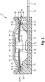
- Fig.1 and 2 each show a schematic sectional view of an embodiment of a temperature-dependent switch according to the invention, in which a switching mechanism according to the invention is used.
- the switch is designated in its entirety with the reference number 10.
- Fig.1 shows the closed position of switch 10.
- Fig. 2 shows the open position of switch 10.
- the switch 10 has a temperature-dependent switching mechanism 12 according to the invention.
- the switching mechanism 12 is designed to switch the switch 10 from its closed position to its open position and vice versa depending on its temperature.
- the switching mechanism 12 In the Fig.1 In the closed position of the switch 10 shown, the switching mechanism 12 establishes an electrically conductive connection between the two external terminals 14, 16 of the switch 10. In the Fig. 2 In the open position of the switch 10 shown, however, the switching mechanism 12 separates the electrically conductive connection between the first external connection 14 and the second external connection 16.
- the temperature-dependent switching mechanism 12 has a temperature-dependent bimetal disk 18, a temperature-independent spring disk 20, a movable contact part 22 and a retaining ring 24.
- the aforementioned components 18-24 of the switching mechanism 12 are connected to one another in a captive manner.
- the spring washer 20 has a central hole through which the contact part 22 is passed.
- the inner edge 26 of the spring washer 20 is clamped to the contact part 22.
- the contact part 22 is constructed in two parts and has a first component 28, which forms the main body of the contact part 22, and a second component 30, which is designed as a kind of circumferential shoulder and is firmly connected to the first component 28 of the contact part 22.
- the spring washer 20 is clamped with its inner edge 26 between the first component 28 and the second component 30 of the contact part 22.
- the peripheral edge 32 of the spring washer 20 is held captive on the retaining ring 24.
- the retaining ring 24 has a base body 34 and a clamping element 36 arranged in the base body 34.
- the base body 34 of the retaining ring 24 is made of metal or another electrically conductive material.
- This base body 34 is a rotationally symmetrical body that extends around a central axis 38 and forms a type of receiving pocket 40 in which the clamping element 36 and the peripheral outer edge 32 of the spring washer 20 are arranged.
- the receiving pocket 40 formed by the base body 34 of the retaining ring 24 is, as in Fig.1 and 2 shown, open towards the central axis 38 and essentially U- or J-shaped in cross section.
- the receiving pocket 40 formed by the base body 34 of the retaining ring 24 extends at least in sections along the retaining ring 24. It can, but does not necessarily have to, run along the entire circumference of the retaining ring 24, as will be explained in more detail below.
- the clamping element 36 is preferably a spacer ring which is designed as a rotating body and is adapted to the shape of the retaining ring or the shape of the receiving pocket 40 formed by the base body 34. This spacer ring is preferably fitted precisely into the receiving pocket 40.
- the spacer ring or the clamping element 36 is preferably made of electrically insulating material, for example plastic.
- the bimetal disk 18 While the spring disk 20 is clamped with its peripheral edge 32 between the base body 34 and the clamping element 36 of the retaining ring 24 and is clamped with its inner edge 26 to the contact part 22, the bimetal disk 18 is in the Fig.1 shown closed position of the switching mechanism 12.
- the bimetal disk 18 is arranged with its inner edge 42 between the second component 30 of the contact part 22, which is designed as a circumferential shoulder, and the spring disk 20.
- This type of arrangement means that the bimetal disk 18 is held captive on the contact part 22, but with play.
- the circumferential edge 44 protrudes into the interior of the switch and has neither contact with the retaining ring 24 nor with the switch housing 46 in which the switching mechanism 12 is arranged.
- the circumferential edge 44 of the bimetal disk 18 is thus at least It is freely accessible from the top and is not covered by the retaining ring 24 from this side.
- the retaining ring 24 surrounds the peripheral edge 32 of the spring washer 20 both from the peripheral side 48 and from the top and bottom sides 50, 52 of the spring washer 20.
- the bimetal disk 18 and the spring disk 20 are arranged one above the other in the height direction h.
- a height H, of the contact part 22 measured in the height direction h is greater than a height H 2 of the retaining ring 24 measured in the height direction h. Accordingly, the contact part 22 protrudes in the Fig.1 shown closed position of the rear derailleur 12 downwards out of the retaining ring 24. In the Fig. 2 In the closed position shown, the contact part 22 protrudes from the retaining ring 24 on both sides (downward and upward).
- an inner diameter d 1 of the base body 34 of the retaining ring 24 is smaller than an outer diameter D of the spring disk 20, but larger than an outer diameter D 1 of the bimetallic disk 18. This ensures that the spring disk 20 is held captive on the retaining ring 24 and cannot accidentally come loose from it. On the other hand, this ensures that the bimetallic disk 18 does not collide with the retaining ring 24 during its temperature-dependent movement.
- the base body 34 of the retaining ring 24 is designed in one piece. It has a ceiling wall 54, a bottom wall 56 which is integrally connected to the ceiling wall 54 and runs parallel thereto, and a side wall 58 which runs transversely to the ceiling wall 54 and the bottom wall 56.
- the side wall 58 connects the ceiling wall 54 to the bottom wall 56 and is integrally connected to both.
- top wall 54 and the bottom wall 56 of the base body 34 of the retaining ring 24 do not necessarily have to run all the way around. Although it is fundamentally It is possible for the top wall 54 to run along the entire circumference of the base body 34 of the retaining ring 24. However, to avoid creases, it is advantageous if the top wall 54 of the base body 34 of the retaining ring 24 has several separate, bent segments 60 distributed in the circumferential direction, as shown in the plan view in Fig.4 is shown.
- the switching mechanism 12 is inserted into the switch housing 46 as a whole during the manufacture of the switch 10.
- This switch housing 46 has a pot-shaped lower part 62, which is closed by a separately designed cover part 64.
- the lower part 62 and the cover part 64 in the switch according to the invention are made of electrically insulating material, e.g. plastic.
- the upper edge 66 of the lower part 62 is stamped onto the cover part in a vacuum-tight manner.
- the upper edge 66 of the lower part 62 is formed radially inwards by hot stamping during the manufacture of the switch 10, so that the lower part 62 is firmly connected to the cover part 64 and the interior of the switch is sealed, in particular to protect the switching mechanism 12 from moisture or other dirt penetrating the interior of the switch.
- the switch housing 46 itself does not serve for the electrical connection of the switching mechanism 12. Instead, the base body 34 of the retaining ring 24, which is made of electrically conductive material, functions as the first electrode 68.
- a second electrode 70 is embedded in the lower part 62 of the switch housing 46. This second electrode 70 is integrally connected to the second external connection 16.
- the second electrode 70 can, for example, be a metal sheet that is directly integrated into the lower part 62 of the switch housing 46.
- the lower part 62 is manufactured as a plastic injection-molded part during the manufacture of the switch 10 by overmolding the second electrode 70.
- the two electrodes 68, 70 of the switching mechanism 12 are held at a distance from one another in the vertical direction h by the lower part 62 of the switch housing 46.
- the retaining ring 24 rests on top of a shoulder 72 formed in the interior of the lower part and is simultaneously connected to a line connecting element 74 which is electrically connected to the first External connection 14 is connected in surface contact.
- This line connection element 74 can be, for example, a line plate or another electrical conductor that is integrated into the lower part 62 of the switch housing 46.
- the line connection element 74 electrically connects the base body 34 of the retaining ring 24, which functions as the first electrode 68 of the switching mechanism 12, to the first external connection 14.
- the first external connection 14 is accordingly in the Fig.1 and 2 shown sectional views "behind" the second external connection 16, since the first external connection 14 is arranged at the same height as the second external connection 16 and runs parallel to the second external connection 16. The latter is particularly evident when viewed in conjunction with the Fig.3 shown top view of the switch 10.
- the two external connections 14, 16 run as in Fig.3 shown, outside the switch housing 46 parallel to each other and can, due to the line connection element 74, in a common connection level E, which in Fig.1 and 2 indicated by a dashed line.
- the line connection element 74 also offers the advantage that the switching mechanism 12 only has to be inserted into the lower part 62 during the manufacture of the switch 10 and the electrical contact between the base body 34 of the retaining ring 24 and the first external connection 14 is then automatically established.
- Fig.3 shows a top view of the switch 10, whereby some components arranged inside the switch housing 46 (e.g. components 18, 20 and 34) are indicated by dashed lines, since they are not actually visible from the outside.
- the dashed lines indicate the outline or the outer circumference of the respective component.
- the second electrode 70 which in Fig.3 also indicated by dashed lines, runs diagonally or angled to the second external connection 16, but, as already mentioned, is located together with the second external connection 16 in the connection level E.
- Fig.1 and 2 therefore show the section along the section line AA.
- the second electrode 70 does not necessarily have to be angled or oblique to the second external connection 16, as is shown in Fig.3 is shown.
- the second electrode 70 can in principle also be aligned with the second external connection 16.
- the second external connection 16 runs together with the second electrode 70 in the radial direction of the switch housing 46. If the second external connection 16 is in the middle, i.e. opposite the Fig.3 shown position is arranged parallel and offset upwards in the direction of the first external connection 14, a parallel alignment of the two external connections 14, 16 is also possible.
- the second external terminal 16 and the second electrode 70 will then be arranged in a line parallel to the first external terminal 14 in the center of the switch housing 46.
- Fig.1 shows, as already mentioned, the closed position of the switch 10, in which the temperature-dependent switching mechanism 12 establishes an electrical contact between the two external connections 14, 16 inside the switch.
- the spring disk 20 presses the contact part 22 against a stationary counter-contact 76, which is attached to the second electrode 70.
- the bimetal disk 18 is in the closed position of the Switch 10 is mounted without current and without force. The contact pressure as well as the current flow is only caused by the spring washer 20.
- the spring washer 20 is supported with its peripheral edge 32 on the clamping element 36 and presses the centrally arranged contact part 22 against the counter contact 76.
- the current flows from the first external connection 14 via the line connection element 74, the retaining ring 24, the spring washer 20, the movable contact part 22, the stationary counter contact 76 and the second electrode 70 to the second external connection 16 (or in the opposite direction).
- the spring disk 20 In the closed position or low-temperature position of the switch 10 shown, the spring disk 20 is in its first configuration and the bimetal disk 18 is in its low-temperature configuration. If, starting from this situation, the temperature of the device to be protected and thus the temperature of the switch 10 and the temperature of the bimetal disk 18 increases to the response temperature of the bimetal disk 18 or above this response temperature, the bimetal disk 18 snaps from its Fig.1 shown, convex low temperature position to its concave high temperature position, which is Fig. 2 As shown in the drawing, the bimetal disk 18 rests with its outer edge 44 on the spring disk 20.
- the device to be protected is then de-energized so that it can cool down again. If the temperature then falls below the so-called recovery temperature of the bimetal disc 18, it snaps back from its Fig. 2 shown high temperature position to its in Fig.1 shown low temperature position, whereby the electrically conductive connection between the two external connections 14, 16 is closed again.
- a switch-back can be prevented by a switch-back lock or a heating resistor connected electrically in parallel to the switching mechanism 12, which causes a so-called self-holding function.
- the switch 10 can be modified in various ways to the embodiment shown in the drawings without departing from the scope of the present invention.
- the switch housing 46 does not necessarily have to be circular in longitudinal section, but can also be oval or square.
- the two disks 18, 20 do not necessarily have to be circular disks.
- the shape of the retaining ring 24, as well as the shape of the contact part 22, can also be designed somewhat differently and does not necessarily have to have exactly the shape shown in the drawings shown here.
Landscapes
- Physics & Mathematics (AREA)
- Thermal Sciences (AREA)
- Thermally Actuated Switches (AREA)
Priority Applications (1)
| Application Number | Priority Date | Filing Date | Title |
|---|---|---|---|
| EP25156933.1A EP4528772B1 (fr) | 2023-01-31 | 2024-01-19 | Mécanisme de commutation dépendant de la température et commutateur dépendant de la température |
Applications Claiming Priority (1)
| Application Number | Priority Date | Filing Date | Title |
|---|---|---|---|
| DE102023102304.7A DE102023102304B4 (de) | 2023-01-31 | 2023-01-31 | Temperaturabhängiges Schaltwerk und temperaturabhängiger Schalter |
Related Child Applications (1)
| Application Number | Title | Priority Date | Filing Date |
|---|---|---|---|
| EP25156933.1A Division EP4528772B1 (fr) | 2023-01-31 | 2024-01-19 | Mécanisme de commutation dépendant de la température et commutateur dépendant de la température |
Publications (1)
| Publication Number | Publication Date |
|---|---|
| EP4411778A1 true EP4411778A1 (fr) | 2024-08-07 |
Family
ID=89661952
Family Applications (2)
| Application Number | Title | Priority Date | Filing Date |
|---|---|---|---|
| EP25156933.1A Active EP4528772B1 (fr) | 2023-01-31 | 2024-01-19 | Mécanisme de commutation dépendant de la température et commutateur dépendant de la température |
| EP24152794.4A Pending EP4411778A1 (fr) | 2023-01-31 | 2024-01-19 | Mécanisme de commutation dépendant de la température et commutateur dépendant de la température |
Family Applications Before (1)
| Application Number | Title | Priority Date | Filing Date |
|---|---|---|---|
| EP25156933.1A Active EP4528772B1 (fr) | 2023-01-31 | 2024-01-19 | Mécanisme de commutation dépendant de la température et commutateur dépendant de la température |
Country Status (5)
| Country | Link |
|---|---|
| US (1) | US20240258054A1 (fr) |
| EP (2) | EP4528772B1 (fr) |
| JP (1) | JP2024109104A (fr) |
| CN (1) | CN118471734A (fr) |
| DE (1) | DE102023102304B4 (fr) |
Citations (7)
| Publication number | Priority date | Publication date | Assignee | Title |
|---|---|---|---|---|
| US2861151A (en) * | 1957-04-22 | 1958-11-18 | Westinghouse Electric Corp | Temperature-controlled apparatus |
| DE2917482A1 (de) | 1979-04-30 | 1980-11-06 | Hofsass P | Waermeschutzschalter |
| DE19919648A1 (de) | 1999-04-30 | 2000-12-07 | Marcel Hofsaess | Gerät mit in einer Tasche vorgesehenem temperaturabhängigen Schaltwerk |
| DE102007014237A1 (de) | 2007-03-16 | 2008-09-18 | Hofsaess, Marcel P. | Temperaturabhängiger Schalter und dafür vorgesehenes Schaltwerk |
| DE102011119632B3 (de) | 2011-11-22 | 2013-04-11 | Marcel P. HOFSAESS | Temperaturabhängiges Schaltwerk |
| DE102013102089A1 (de) | 2013-03-04 | 2014-09-04 | Marcel P. HOFSAESS | Temperaturabhängiger Schalter mit Isolierscheibe |
| DE102013017232A1 (de) * | 2013-10-17 | 2015-04-23 | Thermik Gerätebau GmbH | Temperaturabhängiges Schaltwerk |
Family Cites Families (12)
| Publication number | Priority date | Publication date | Assignee | Title |
|---|---|---|---|---|
| DE19527253B4 (de) * | 1995-07-26 | 2006-01-05 | Thermik Gerätebau GmbH | Nach dem Baukastenprinzip aufgebauter Temperaturwächter |
| DE19527254C2 (de) * | 1995-07-26 | 2000-01-20 | Thermik Geraetebau Gmbh | Temperaturwächter |
| DE19609577C2 (de) * | 1996-03-12 | 1998-02-19 | Thermik Geraetebau Gmbh | Schalter mit einem temperaturabhängigen Schaltwerk |
| US6069551A (en) * | 1997-05-02 | 2000-05-30 | Therm-O-Disc, Incorporated | Thermal switch assembly |
| DE19847208C2 (de) * | 1998-10-13 | 2002-05-16 | Marcel Hofsaes | Schalter mit einem Isolierstoffträger |
| KR20110005879A (ko) * | 2008-04-18 | 2011-01-19 | 타이코 일렉트로닉스 저팬 지.케이. | 회로 보호 디바이스 |
| DE102012112487A1 (de) * | 2012-12-18 | 2014-06-18 | Thermik Gerätebau GmbH | Temperaturschutzschaltung |
| DE102013109291A1 (de) * | 2013-08-27 | 2015-03-05 | Thermik Gerätebau GmbH | Temperaturabhängiger Schalter mit am Rand eingeklemmter Schnappscheibe |
| DE102014108518A1 (de) * | 2014-06-17 | 2015-12-17 | Thermik Gerätebau GmbH | Temperaturabhängiger Schalter mit Distanzring |
| JP2016096119A (ja) * | 2014-11-17 | 2016-05-26 | 株式会社小松ライト製作所 | ブレーカー及びそれを備えた安全回路並びに2次電池回路。 |
| DE102019125452B4 (de) * | 2019-09-20 | 2021-04-22 | Marcel P. HOFSAESS | Temperaturabhängiger Schalter |
| DE102019125451B4 (de) * | 2019-09-20 | 2021-04-08 | Marcel P. HOFSAESS | Temperaturabhängiger Schalter |
-
2023
- 2023-01-31 DE DE102023102304.7A patent/DE102023102304B4/de active Active
-
2024
- 2024-01-19 EP EP25156933.1A patent/EP4528772B1/fr active Active
- 2024-01-19 EP EP24152794.4A patent/EP4411778A1/fr active Pending
- 2024-01-30 US US18/427,728 patent/US20240258054A1/en active Pending
- 2024-01-30 CN CN202410132057.0A patent/CN118471734A/zh active Pending
- 2024-01-30 JP JP2024012304A patent/JP2024109104A/ja active Pending
Patent Citations (7)
| Publication number | Priority date | Publication date | Assignee | Title |
|---|---|---|---|---|
| US2861151A (en) * | 1957-04-22 | 1958-11-18 | Westinghouse Electric Corp | Temperature-controlled apparatus |
| DE2917482A1 (de) | 1979-04-30 | 1980-11-06 | Hofsass P | Waermeschutzschalter |
| DE19919648A1 (de) | 1999-04-30 | 2000-12-07 | Marcel Hofsaess | Gerät mit in einer Tasche vorgesehenem temperaturabhängigen Schaltwerk |
| DE102007014237A1 (de) | 2007-03-16 | 2008-09-18 | Hofsaess, Marcel P. | Temperaturabhängiger Schalter und dafür vorgesehenes Schaltwerk |
| DE102011119632B3 (de) | 2011-11-22 | 2013-04-11 | Marcel P. HOFSAESS | Temperaturabhängiges Schaltwerk |
| DE102013102089A1 (de) | 2013-03-04 | 2014-09-04 | Marcel P. HOFSAESS | Temperaturabhängiger Schalter mit Isolierscheibe |
| DE102013017232A1 (de) * | 2013-10-17 | 2015-04-23 | Thermik Gerätebau GmbH | Temperaturabhängiges Schaltwerk |
Also Published As
| Publication number | Publication date |
|---|---|
| EP4528772A2 (fr) | 2025-03-26 |
| CN118471734A (zh) | 2024-08-09 |
| EP4528772A3 (fr) | 2025-06-04 |
| DE102023102304B4 (de) | 2024-08-08 |
| US20240258054A1 (en) | 2024-08-01 |
| EP4528772B1 (fr) | 2026-05-13 |
| DE102023102304A1 (de) | 2024-08-01 |
| JP2024109104A (ja) | 2024-08-13 |
Similar Documents
| Publication | Publication Date | Title |
|---|---|---|
| EP2874171B1 (fr) | Mécanisme de commutation variable avec la température | |
| EP4310879B1 (fr) | Mécanisme de commutation dépendant de la température et interrupteur dépendant de la température doté d'un tel mécanisme de commutation | |
| EP2854149B1 (fr) | Commutateur thermosensible doté d'un disque à action rapide disposé sur le bord | |
| DE102022134380B3 (de) | Temperaturabhängige Schaltwerke und temperaturabhängiger Schalter mit einem solchen Schaltwerk | |
| EP4325541B1 (fr) | Commutateur dépendant de la température | |
| EP2783380B1 (fr) | Mécanisme interrupteur actionné thermiquement | |
| EP4258316B1 (fr) | Commutateur dépendant de la température | |
| EP4546389B1 (fr) | Commutateur dépendant de la température | |
| EP4310878B1 (fr) | Mécanisme de commutation dépendant de la température, commutateur dépendant de la température et procédé de fabrication d'un mécanisme de commutation dépendant de la température | |
| EP0778596A2 (fr) | Interrupteur avec un mécanisme de commutation sensible à la température | |
| CH661815A5 (de) | Thermischer schalter. | |
| DE102023102304B4 (de) | Temperaturabhängiges Schaltwerk und temperaturabhängiger Schalter | |
| DE102023102302B3 (de) | Temperaturabhängiger Schalter | |
| DE102023005419A1 (de) | Temperaturabhängiges Schaltwerk und temperaturabhängiger Schalter | |
| DE102023104807B3 (de) | Temperaturabhängiger Schalter | |
| EP4325543B1 (fr) | Commutateur dépendant de la température | |
| DE102023104836B3 (de) | Temperaturabhängiges Schaltwerk und temperaturabhängiger Schalter | |
| DE102022134379B3 (de) | Temperaturabhängiger Schalter | |
| DE102022120447B3 (de) | Temperaturabhängiger Schalter | |
| DE102023127597B3 (de) | Temperaturabhängiger Schalter | |
| EP4539082A1 (fr) | Mécanisme de commutation dépendant de la température et interrupteur dépendant de la température doté d'un tel mécanisme de commutation |
Legal Events
| Date | Code | Title | Description |
|---|---|---|---|
| PUAI | Public reference made under article 153(3) epc to a published international application that has entered the european phase |
Free format text: ORIGINAL CODE: 0009012 |
|
| STAA | Information on the status of an ep patent application or granted ep patent |
Free format text: STATUS: THE APPLICATION HAS BEEN PUBLISHED |
|
| AK | Designated contracting states |
Kind code of ref document: A1 Designated state(s): AL AT BE BG CH CY CZ DE DK EE ES FI FR GB GR HR HU IE IS IT LI LT LU LV MC ME MK MT NL NO PL PT RO RS SE SI SK SM TR |
|
| STAA | Information on the status of an ep patent application or granted ep patent |
Free format text: STATUS: REQUEST FOR EXAMINATION WAS MADE |
|
| 17P | Request for examination filed |
Effective date: 20250129 |
|
| GRAP | Despatch of communication of intention to grant a patent |
Free format text: ORIGINAL CODE: EPIDOSNIGR1 |
|
| STAA | Information on the status of an ep patent application or granted ep patent |
Free format text: STATUS: GRANT OF PATENT IS INTENDED |
|
| RIC1 | Information provided on ipc code assigned before grant |
Ipc: H01H 37/54 20060101AFI20260401BHEP Ipc: H01H 37/06 20060101ALN20260401BHEP |
|
| INTG | Intention to grant announced |
Effective date: 20260410 |