EP4412192B1 - Hintergrundlichtsubtraktion für infrarotbilder - Google Patents
Hintergrundlichtsubtraktion für infrarotbilder Download PDFInfo
- Publication number
- EP4412192B1 EP4412192B1 EP23154105.3A EP23154105A EP4412192B1 EP 4412192 B1 EP4412192 B1 EP 4412192B1 EP 23154105 A EP23154105 A EP 23154105A EP 4412192 B1 EP4412192 B1 EP 4412192B1
- Authority
- EP
- European Patent Office
- Prior art keywords
- image
- pixels
- light
- illuminated
- rolling shutter
- Prior art date
- Legal status (The legal status is an assumption and is not a legal conclusion. Google has not performed a legal analysis and makes no representation as to the accuracy of the status listed.)
- Active
Links
Images



Classifications
-
- H—ELECTRICITY
- H04—ELECTRIC COMMUNICATION TECHNIQUE
- H04N—PICTORIAL COMMUNICATION, e.g. TELEVISION
- H04N23/00—Cameras or camera modules comprising electronic image sensors; Control thereof
- H04N23/80—Camera processing pipelines; Components thereof
-
- H—ELECTRICITY
- H04—ELECTRIC COMMUNICATION TECHNIQUE
- H04N—PICTORIAL COMMUNICATION, e.g. TELEVISION
- H04N7/00—Television systems
- H04N7/18—Closed-circuit television [CCTV] systems, i.e. systems in which the video signal is not broadcast
- H04N7/183—Closed-circuit television [CCTV] systems, i.e. systems in which the video signal is not broadcast for receiving images from a single remote source
-
- H—ELECTRICITY
- H04—ELECTRIC COMMUNICATION TECHNIQUE
- H04N—PICTORIAL COMMUNICATION, e.g. TELEVISION
- H04N25/00—Circuitry of solid-state image sensors [SSIS]; Control thereof
- H04N25/50—Control of the SSIS exposure
- H04N25/53—Control of the integration time
-
- G—PHYSICS
- G06—COMPUTING OR CALCULATING; COUNTING
- G06T—IMAGE DATA PROCESSING OR GENERATION, IN GENERAL
- G06T5/00—Image enhancement or restoration
- G06T5/50—Image enhancement or restoration using two or more images, e.g. averaging or subtraction
-
- G—PHYSICS
- G06—COMPUTING OR CALCULATING; COUNTING
- G06V—IMAGE OR VIDEO RECOGNITION OR UNDERSTANDING
- G06V10/00—Arrangements for image or video recognition or understanding
- G06V10/10—Image acquisition
- G06V10/12—Details of acquisition arrangements; Constructional details thereof
- G06V10/14—Optical characteristics of the device performing the acquisition or on the illumination arrangements
- G06V10/143—Sensing or illuminating at different wavelengths
-
- G—PHYSICS
- G06—COMPUTING OR CALCULATING; COUNTING
- G06V—IMAGE OR VIDEO RECOGNITION OR UNDERSTANDING
- G06V20/00—Scenes; Scene-specific elements
- G06V20/50—Context or environment of the image
- G06V20/52—Surveillance or monitoring of activities, e.g. for recognising suspicious objects
- G06V20/54—Surveillance or monitoring of activities, e.g. for recognising suspicious objects of traffic, e.g. cars on the road, trains or boats
-
- G—PHYSICS
- G06—COMPUTING OR CALCULATING; COUNTING
- G06V—IMAGE OR VIDEO RECOGNITION OR UNDERSTANDING
- G06V20/00—Scenes; Scene-specific elements
- G06V20/60—Type of objects
- G06V20/62—Text, e.g. of license plates, overlay texts or captions on TV images
- G06V20/625—License plates
-
- H—ELECTRICITY
- H04—ELECTRIC COMMUNICATION TECHNIQUE
- H04N—PICTORIAL COMMUNICATION, e.g. TELEVISION
- H04N23/00—Cameras or camera modules comprising electronic image sensors; Control thereof
- H04N23/10—Cameras or camera modules comprising electronic image sensors; Control thereof for generating image signals from different wavelengths
-
- H—ELECTRICITY
- H04—ELECTRIC COMMUNICATION TECHNIQUE
- H04N—PICTORIAL COMMUNICATION, e.g. TELEVISION
- H04N23/00—Cameras or camera modules comprising electronic image sensors; Control thereof
- H04N23/10—Cameras or camera modules comprising electronic image sensors; Control thereof for generating image signals from different wavelengths
- H04N23/11—Cameras or camera modules comprising electronic image sensors; Control thereof for generating image signals from different wavelengths for generating image signals from visible and infrared light wavelengths
-
- H—ELECTRICITY
- H04—ELECTRIC COMMUNICATION TECHNIQUE
- H04N—PICTORIAL COMMUNICATION, e.g. TELEVISION
- H04N23/00—Cameras or camera modules comprising electronic image sensors; Control thereof
- H04N23/20—Cameras or camera modules comprising electronic image sensors; Control thereof for generating image signals from infrared radiation only
-
- H—ELECTRICITY
- H04—ELECTRIC COMMUNICATION TECHNIQUE
- H04N—PICTORIAL COMMUNICATION, e.g. TELEVISION
- H04N23/00—Cameras or camera modules comprising electronic image sensors; Control thereof
- H04N23/20—Cameras or camera modules comprising electronic image sensors; Control thereof for generating image signals from infrared radiation only
- H04N23/21—Cameras or camera modules comprising electronic image sensors; Control thereof for generating image signals from infrared radiation only from near infrared [NIR] radiation
-
- H—ELECTRICITY
- H04—ELECTRIC COMMUNICATION TECHNIQUE
- H04N—PICTORIAL COMMUNICATION, e.g. TELEVISION
- H04N23/00—Cameras or camera modules comprising electronic image sensors; Control thereof
- H04N23/20—Cameras or camera modules comprising electronic image sensors; Control thereof for generating image signals from infrared radiation only
- H04N23/23—Cameras or camera modules comprising electronic image sensors; Control thereof for generating image signals from infrared radiation only from thermal infrared radiation
-
- H—ELECTRICITY
- H04—ELECTRIC COMMUNICATION TECHNIQUE
- H04N—PICTORIAL COMMUNICATION, e.g. TELEVISION
- H04N23/00—Cameras or camera modules comprising electronic image sensors; Control thereof
- H04N23/56—Cameras or camera modules comprising electronic image sensors; Control thereof provided with illuminating means
-
- H—ELECTRICITY
- H04—ELECTRIC COMMUNICATION TECHNIQUE
- H04N—PICTORIAL COMMUNICATION, e.g. TELEVISION
- H04N23/00—Cameras or camera modules comprising electronic image sensors; Control thereof
- H04N23/70—Circuitry for compensating brightness variation in the scene
- H04N23/71—Circuitry for evaluating the brightness variation
-
- H—ELECTRICITY
- H04—ELECTRIC COMMUNICATION TECHNIQUE
- H04N—PICTORIAL COMMUNICATION, e.g. TELEVISION
- H04N23/00—Cameras or camera modules comprising electronic image sensors; Control thereof
- H04N23/70—Circuitry for compensating brightness variation in the scene
- H04N23/72—Combination of two or more compensation controls
-
- H—ELECTRICITY
- H04—ELECTRIC COMMUNICATION TECHNIQUE
- H04N—PICTORIAL COMMUNICATION, e.g. TELEVISION
- H04N23/00—Cameras or camera modules comprising electronic image sensors; Control thereof
- H04N23/70—Circuitry for compensating brightness variation in the scene
- H04N23/73—Circuitry for compensating brightness variation in the scene by influencing the exposure time
-
- H—ELECTRICITY
- H04—ELECTRIC COMMUNICATION TECHNIQUE
- H04N—PICTORIAL COMMUNICATION, e.g. TELEVISION
- H04N23/00—Cameras or camera modules comprising electronic image sensors; Control thereof
- H04N23/70—Circuitry for compensating brightness variation in the scene
- H04N23/74—Circuitry for compensating brightness variation in the scene by influencing the scene brightness using illuminating means
-
- H—ELECTRICITY
- H04—ELECTRIC COMMUNICATION TECHNIQUE
- H04N—PICTORIAL COMMUNICATION, e.g. TELEVISION
- H04N23/00—Cameras or camera modules comprising electronic image sensors; Control thereof
- H04N23/70—Circuitry for compensating brightness variation in the scene
- H04N23/741—Circuitry for compensating brightness variation in the scene by increasing the dynamic range of the image compared to the dynamic range of the electronic image sensors
-
- H—ELECTRICITY
- H04—ELECTRIC COMMUNICATION TECHNIQUE
- H04N—PICTORIAL COMMUNICATION, e.g. TELEVISION
- H04N23/00—Cameras or camera modules comprising electronic image sensors; Control thereof
- H04N23/70—Circuitry for compensating brightness variation in the scene
- H04N23/76—Circuitry for compensating brightness variation in the scene by influencing the image signals
-
- H—ELECTRICITY
- H04—ELECTRIC COMMUNICATION TECHNIQUE
- H04N—PICTORIAL COMMUNICATION, e.g. TELEVISION
- H04N25/00—Circuitry of solid-state image sensors [SSIS]; Control thereof
- H04N25/10—Circuitry of solid-state image sensors [SSIS]; Control thereof for transforming different wavelengths into image signals
- H04N25/11—Arrangement of colour filter arrays [CFA]; Filter mosaics
- H04N25/13—Arrangement of colour filter arrays [CFA]; Filter mosaics characterised by the spectral characteristics of the filter elements
- H04N25/131—Arrangement of colour filter arrays [CFA]; Filter mosaics characterised by the spectral characteristics of the filter elements including elements passing infrared wavelengths
-
- H—ELECTRICITY
- H04—ELECTRIC COMMUNICATION TECHNIQUE
- H04N—PICTORIAL COMMUNICATION, e.g. TELEVISION
- H04N25/00—Circuitry of solid-state image sensors [SSIS]; Control thereof
- H04N25/20—Circuitry of solid-state image sensors [SSIS]; Control thereof for transforming only infrared radiation into image signals
-
- H—ELECTRICITY
- H04—ELECTRIC COMMUNICATION TECHNIQUE
- H04N—PICTORIAL COMMUNICATION, e.g. TELEVISION
- H04N25/00—Circuitry of solid-state image sensors [SSIS]; Control thereof
- H04N25/50—Control of the SSIS exposure
- H04N25/53—Control of the integration time
- H04N25/531—Control of the integration time by controlling rolling shutters in CMOS SSIS
-
- H—ELECTRICITY
- H04—ELECTRIC COMMUNICATION TECHNIQUE
- H04N—PICTORIAL COMMUNICATION, e.g. TELEVISION
- H04N25/00—Circuitry of solid-state image sensors [SSIS]; Control thereof
- H04N25/50—Control of the SSIS exposure
- H04N25/57—Control of the dynamic range
- H04N25/58—Control of the dynamic range involving two or more exposures
- H04N25/587—Control of the dynamic range involving two or more exposures acquired sequentially, e.g. using the combination of odd and even image fields
-
- H—ELECTRICITY
- H04—ELECTRIC COMMUNICATION TECHNIQUE
- H04N—PICTORIAL COMMUNICATION, e.g. TELEVISION
- H04N25/00—Circuitry of solid-state image sensors [SSIS]; Control thereof
- H04N25/70—SSIS architectures; Circuits associated therewith
- H04N25/703—SSIS architectures incorporating pixels for producing signals other than image signals
- H04N25/706—Pixels for exposure or ambient light measuring
-
- G—PHYSICS
- G06—COMPUTING OR CALCULATING; COUNTING
- G06T—IMAGE DATA PROCESSING OR GENERATION, IN GENERAL
- G06T2207/00—Indexing scheme for image analysis or image enhancement
- G06T2207/10—Image acquisition modality
- G06T2207/10048—Infrared image
Definitions
- the present disclosure generally relates to background light subtraction in an infra-red (IR) image depicting a scene, and more specifically to background light subtraction in an IR image using a non-IR image, where both images being captured by a rolling shutter image sensor.
- IR infra-red
- Infra-red (IR) images can be advantageous in a variety of situations where visual information is not sufficient to detect or analyse objects or phenomena.
- a common example includes night-time or low-light conditions where IR cameras can capture images in the dark, making them useful for monitoring applications, search and rescue, and other applications that require visibility in low-light environments.
- One example includes using a camera with infra-red lights to read license plates, road signs or detect traffic cones in low-light conditions. License plates, road signs and traffic cones are typically made of reflecting material such as a retroreflector and return much IR-light.
- a problem is that strong light sources in the captured scene, such as headlights of a vehicle, can be directed into the camera and cause scattering and reflexes that cover the object to be detected and makes it hard for analytics software to find and analyse the object (e.g., reading the license plate, determining content in road sign, etc.,).
- Another existing solution includes syncing the IR-lights on the camera with the frame capture of the sensor of the camera.
- the IR-lights are switched on for one full frame, and then off for the next full frame.
- the image without IR is subtracted from the image with IR.
- Running the sensor at a high frame rate, for example 60 fps, makes it possible to capture video in half that frame rate, 30 fps, with background light subtracted from the IR-image.
- a problem with this solution is if the camera moves (e.g., a camera in a car) or if the scene moves (e.g., the scene includes a road), then the time difference between capturing of the two images only allows movements (objects in the scene and/or the camera) at a low speed (depending on zoom level, and application specific requirements for e.g., level of details, etc.) for the background light subtraction to work sufficiently well.
- EP2938065 A1 (THOMSON LICENSING [FR]) describes an image acquisition system for capturing images of a scene comprising at least one light unit for illuminating the scene; a light control device for controlling illumination by the at least one light unit in accordance with a plurality of illumination configurations applied in an alternate manner; an imaging device for capturing a sequence of images of the illuminated scene; the sequence of images comprising a plurality of interleaved series of images, each image series corresponding to a respective illumination configuration.
- EP2448251 A2 (MOBILEYE TECHNOLOGIES LTD [CY]) describes a system mountable in a motor vehicle that includes a camera and a processor configured to receive image data from the camera.
- the camera includes a rolling shutter configured to capture the image data during a frame period and to scan and to read the image data into multiple image frames.
- a near infra-red illuminator may be configured to provide a near infra-red illumination cone in the field of view of the camera.
- the near infrared illumination oscillates with an illumination period.
- a synchronization mechanism may be configured to synchronize the illumination period to the frame period of the rolling shutter.
- IR infra-red
- the method further comprises creating an IR-illuminated image based at least in part on the first set of lines of the two or more image frames and creating a non-IR-illuminated image based at least in part on the second set of lines of the two or more image frames.
- the method further comprises subtracting background light from the IR-illuminated image using pixel values in the non-IR-illuminated image, thereby creating a modified IR-illuminated image.
- the step of capturing three image frames comprises:
- X and y are positive natural numbers.
- a rolling shutter image sensor is a type of image sensor that captures images by scanning the scene progressively, row by row or column by column, rather than all at once. This means that the image is not captured all at once, but rather is constructed from a series of individual scan lines.
- the advantage of a rolling shutter is that it allows for faster image capture rates.
- a rolling shutter image sensor is used to capture high dynamic range (HDR) images, where the rolling shutter image sensor can be used to capture a series of images with different exposures (e.g., one image with a short exposure time and one image with a long exposure time) in rapid succession, which can then be combined to create an HDR image.
- the rolling shutter image sensor may be configured such that a first and second image is captured with the same or similar exposure time.
- a rolling shutter image sensor comprises sensors manufactured by Sony and Omnivision, such as CMOS image sensors supporting a DOL WDR (digital overlap wide dynamic range) function.
- each image of the at least two images will comprise lines of pixels captured with the IR light turned on, and a lines of pixels captured with the IP light turned off.
- the on-off cycle of the IR light can be synchronized with the exposure time and the time difference between the two and more captured images, making it possible to stitch an IR-illuminated image comprising (mostly or only) image data captured with the IR light turned on from the first set of lines of pixels in the respective captured image.
- the difference in capturing time of the IR-illuminated image and the non-IR-illuminated image may thus be small enough to allow for subtraction of background light from the IR illuminated image using pixel values in the non-IR-illuminated image, even if movements of the camera and/or the objects in the scene are substantial.
- background light should, in the context of present specification, be understood any light in an image that negatively affects detection and analysis of objects being of interest in the image.
- the background light may result from natural sources such as the sun or the moon, but typically the background light results from bright artificial sources of light such as headlights of a vehicle, spotlights, streetlights, etc, causing adverse reflections and scattering in the image.
- the non-IR-illuminated image and the IR-illuminated image may have the same resolution, which simplifies subtraction since the pixel value of a pixel at coordinate (X,Y) in the non-IR illuminated image may be subtracted from the pixel value of the pixel at the same coordinate (X, Y) in the IR-illuminated image, otherwise, necessary scale transforms of the coordinate space in one of the image may be needed.
- the IR-illuminated image and the non-IR illuminated image is captured using the same colour space, such as for example grayscale, RGB, CMYK etc, subtraction may be performed directly using element-wise arithmetic.
- the step of subtracting comprises, for each pixel coordinate of at least a sub-set of pixel coordinates in the non-IR-illuminated image, subtracting the pixel value at the pixel coordinate in the non-IR-illuminated image from the pixel value at a corresponding pixel coordinate in of the IR-illuminated image.
- this may increase details and sense of faithfulness in the modified IR illuminated image since areas of the image not affected by e.g., strong headlights need not to be modified as described herein.
- the sub-set of pixel coordinates is selected based on luminosity (lightness, etc.,) of the pixel values in the non-IR-illuminated image.
- the method thus comprises the step of selecting the sub-set of pixel coordinates based on luminosity of the pixel values in the non-IR-illuminated image.
- a luminosity of a pixel at (X, Y) exceeds a threshold luminosity (e.g., 80, 90 or any other suitable threshold in the LAB colour space, or e.g., 200, 215 or any other suitable threshold in the grayscale colour space)
- a threshold luminosity e.g. 80, 90 or any other suitable threshold in the LAB colour space, or e.g., 200, 215 or any other suitable threshold in the grayscale colour space
- the step of subtracting comprises, for each pixel coordinate of at least a sub-set of pixel coordinates in the non-IR-illuminated image, multiplying the pixel value at the pixel coordinate in the non-IR-illuminated image with a weight value, and subtracting the weighted pixel value at the pixel coordinate in the non-IR-illuminated image from the pixel value at a corresponding pixel coordinate in the IR-illuminated image.
- subtracting a fraction such as 10%, 50%, 60%, etc.
- the present embodiment allows for subtraction of different fractions of the background intensity, such that the of the amount of background subtracted and the amount of noise added may be optimized for each scene.
- the method comprises capturing a first image frame and a second image frame.
- This can be achieved by the step of continuously changing an on-off status of the IR light comprising completing an on-off cycle of the IR light during a first time span, t span , wherein the IR light is turned on during a first half of the time span and turned off during a second half of that time span.
- readout of lines of pixels to the two images can be implemented such that, for the first image, the rolling shutter image sensor reads out a first line of pixels at a first point in time, t, and for the second image, the rolling shutter image sensor reads out the first line of pixels at t + t span 2 .
- This pattern may then be kept for all lines of pixels in the first and second image, such that a line of pixels in the second image are read out at a point in time that is 0.5 t span after the corresponding lines of pixels was read out for the first image.
- the exposure time for each line of pixels may be less than 0.5 milliseconds. Even if that is a short exposure time, it still means that some lines of pixels will be exposed with both IR-light on and off.
- the method comprises capturing a third image frame. Then, readout of lines of pixels to the three images can be implemented such that, for the first image, the rolling shutter image sensor reads out a first line of pixels at a first point in time, t.
- the rolling shutter image sensor reads out the first line of pixels at t + t span 3
- the rolling shutter image sensor reads out the first line of pixels at t + 2 ⁇ t span 3 .
- t span i.e., the time span for completing an on-off cycle of the IR light
- t span in the three-image setup may be the same as t span in the two-image setup or it may be different.
- This pattern may then be kept for all lines of pixels in the first, second and third image, such that a line of pixels in the second image always are read out at a point in time that is 0.33 t span after the corresponding lines of pixels was read out for the first image and such that a line of pixels in the third image always are read out at a point in time that is 0.66 t span after the corresponding lines of pixels was read out for the first image. Consequently, line data from the first, second, and third exposures may be interleaved in time.
- t span may be at least 2 times the exposure time of any line of pixels in the two or more image frames. Consequently, a line of pixels has been exposed and read out in the first image before the corresponding line of pixels is exposed and read out in the second image. It should be noted that t span in some embodiments are anywhere between 2-4 times the exposure time. In the two frames embodiment, a longer time span may result in fewer regions with lines of pixels exposed with both IR-light on and off. A longer time span will result in a larger time separation between the frames, which may suffice when movements of the camera or an object in the scene is not as high, or when the requirements of level of details in images capturing the scene is not as high.
- the IR-illuminated image may be created using only lines of pixels that are exposed with the IR-light on.
- the non-IR-illuminated image may be created using only lines of pixels that are exposed with the IR-light off.
- the method comprises an initial step of determining a luminosity value of natural light in the scene, wherein, upon determining that the luminosity value exceeds a threshold luminosity, the method is aborted, and upon determining that the luminosity value does not exceed a threshold luminosity, the method is continued. Accordingly, the IR-lights are only used when it is not enough natural light present in the scene to capture details using only the natural light as illumination.
- the rolling shutter image sensor is configured to have a same exposure time for all lines of pixels. This reduces complexity and simplifies the process of creating the IR-illuminated image and the non-IR-illuminated image.
- the rolling shutter image sensor is provided in a camera capturing a scene comprising a road.
- the present disclosure enables background subtraction even when the scene changes rapidly.
- An example is a traffic scenario.
- the method further comprises the step of detecting a license plate in the modified IR illuminated image. Identifying license plates may advantageously be done using IR-illumination, since a license plate may be a retro reflector and returns a lot of IR light. Consequently, license plate detection may advantageously be implemented with background subtraction according to the present disclosure.
- a system comprising: a rolling shutter image sensor with a plurality lines of pixels, wherein the rolling shutter image sensor during capture of an image reads out pixel data from one line of pixels at a time; an IR light configured to be turned on and off, wherein when being turned on, the IR light is configured to illuminate the scene; an IR light controlling unit configured to changing an on-off status of the IR light a plurality of times while capturing an image with the rolling shutter image sensor.
- the rolling shutter image sensor is configured for capturing (S708) three image frames (302, 304, 306), the three image frames being captured in a chronological order and comprising a first image frame in chronological order and a last image frame in a chronological order, wherein the rolling shutter image sensor being configured to read out image data to the three image frames interleaved in time, such that read-out of a first line of pixels for the last image frame is performed prior to read-out of a last line of pixels to the first image frame, each image frame comprising: a first set of lines of pixels exposed only with the IR light turned on; a second set of lines of pixels exposed only with the IR light turned off; and a third set of lines of pixels exposed with the IR light turned both on and off.
- the rolling shutter image sensor is configured for: capturing a first image frame (302), a second image frame (304) and a third image frame (306); reading out a first line of pixels (212) for the first image frame (302) at a first point in time, t; reading out the first line of pixels (212) for the second image frame (304) at t + x ⁇ t span _ 2 3 ; and reading out the first line of pixels (212) for the third image frame (306) at t + y * ( 2 ⁇ t span _ 2 3 ); wherein x and y are positive natural numbers
- the system further comprises an image stitching unit configured to: create (S710) an IR-illuminated image using only the first set of lines of the three image frames; create (S712) a non-IR-illuminated image using only the second set of lines of the three frames; and subtract background light from the IR-illuminated image using pixel values in the non-IR-illuminated image, thereby creating a modified IR-illuminated image.
- an image stitching unit configured to: create (S710) an IR-illuminated image using only the first set of lines of the three image frames; create (S712) a non-IR-illuminated image using only the second set of lines of the three frames; and subtract background light from the IR-illuminated image using pixel values in the non-IR-illuminated image, thereby creating a modified IR-illuminated image.
- the system further comprises an image analysis unit configured to detect a license plate in the modified IR illuminated image.
- the above object is achieved by a non-transitory computer-readable storage medium having stored thereon instructions for implementing the method according to the first aspect when executed on a device having processing capabilities.
- the second and third aspects may generally have the same features and advantages as the first aspect. It is further noted that the disclosure relates to all possible combinations of features unless explicitly stated otherwise.
- the present disclosure relates to the field of background light subtraction.
- IR-images may advantageously be used to detect and analyse objects in a scene.
- the scene depicted in the IR-image comprises one or more strong light sources, such as streetlamps, car headlights, etc., these may cause scattering and reflexes that cover the object to be detected and makes it hard for analytics software to find and analyse the object in the IR-image.
- the present disclosure aims to provide methods, systems, devices and software to be used for background light subtraction in such scenarios, and in particular in scenarios where the objects to be detected moves in the scene or when the camera capturing the scene moves.
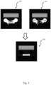
- Figure 1 schematically shows such a low light scenario comprising a vehicle with headlights and a license plate.
- an IR-illuminated image 102 and a non-IR-illuminated image 104 have been created as discussed above and further below in conjunction with figures 2-7 .
- the headlights in the IR-illuminated image 102 reduces the visibility of the license plate, e.g., due to scattering and/or reflexes resulting from the headlights being directed into the camera capturing the IR-illuminated image 102.
- pixel values from the non-IR-illuminated image 104 may be used to subtract the disturbing light from the IR-illuminated image 102 such that the license plate may be readily detected and analysed.
- a modified IR-illuminated image 106 is shown, in which background light from the IR-illuminated image 102 has been subtracted using pixel values in the non-IR-illuminated image 104.
- the license plate is clearly detectable and may be analysed to detect the registration identifier (AXIS 1) which is the alphanumeric ID that uniquely identifies the vehicle or the vehicle owner.
- the pixel values from the entire non-IR-illuminated image 104 (e.g., all pixels in the non-IR-illuminated image 104) is used for subtraction of the background light in the IR-illuminated image.
- a sub-set of pixel coordinates is determined from the non-IR-illuminated image such that background light subtraction only is applied to a corresponding sub-set of pixels in the IR-illuminated image 102 when creating the modified IR-illuminated image 106.
- the sub-set of pixel coordinates in the non-IR-illuminated image 104 may be determined based on an analysis of luminosity of the pixel values in the non-IR-illuminated image 104, such that a coordinate of a pixel is included in the sub-set of pixel coordinates in case the luminosity of the pixel exceeds a threshold value. Limiting the set of pixels used for background subtractions may reduce the noise added to the modified IR-illuminated image 104 due to the subtraction operation.
- FIG. 1 The concept of selecting a sub-set of pixel coordinates for subtraction is exemplified in figure 1 wherein the coordinates of the pixel data 108, 110 corresponding to the headlights and glares from the headlights in the non-IR-illuminated image 104 may be included in the sub-set. It should be noted that this sub-set of pixel coordinates 108, 110 is used as an example for ease of explanation of the concept of selecting pixel coordinates based on the luminosity value.
- the pixel values may be weighted with a weight value (e.g., between 0-1, such as 0.1, 0.5, 0.9, etc.) before being used for subtraction of background light.
- a weight value e.g., between 0-1, such as 0.1, 0.5, 0.9, etc.
- Subtracting a fraction (such as 10%, 50%, 90%, etc.) of the background light from the non-IR-illuminated image 104 may result in that less noise is added to the modified IR-illuminated image compared to the case where the full pixel values of the non-IR-illuminated image is subtracted.
- the non-IR-illuminated image 104 and the IR-illuminated image 102 is captured using the same colour space.
- subtraction may be performed directly using element-wise arithmetic, e.g., by subtracting the RGB values of a pixel in the non-IR-illuminated image 104 from the RBG values of the corresponding pixel in the IR-illuminated image 102.
- one or both of the non-IR-illuminated image 104 and the IR-illuminated image 102 is converted to another colour space before performing the subtraction, for example to the LAB colour space such that the L channel of the non-IR-illuminated image 104 is subtracted from the from the L channel of the IR-illuminated image 102.
- the resulting modified IR-illuminated image 106 may or may not be transformed back to the original colour space of the IR-illuminated image 102.
- the subtraction may be achieved by converting one or both to a different colour space prior to subtracting. For example, in case the IR-illuminated image 104 is a grayscale image and the non-IR-illuminated image 104 is a RGB image, the following steps may be performed:
- Any other suitable transformations and/or scaling of one or both of the non-IR-illuminated image 104 and the IR-illuminated image 102 may be performed before performing the subtraction.
- the non-IR-illuminated image 104 and the IR-illuminated image 102 is advantageously captured close in time. This may be achieved using a rolling shutter image sensor which supports capturing two or more images with a smaller time difference compared to the readout time of the full sensor (e.g., first capturing the non-IR-illuminated image 104 and then the IR-illuminated image 102 or the other way around).
- the rolling shutter image sensor supports an interleaved configuration which now will be described in conjunction with figure 2 .
- Figure 2 schematically shows capturing of two image frames interleaved in time using a rolling shutter image sensor and modulated IR light source.
- the rolling shutter image sensor is configured such that, during capture of an image, it reads out pixel data from one line of pixels at a time. Consequently, by modulating the IR light source such that it changes an on-off status 206 a plurality of times while capturing an image with the rolling shutter image sensor, each of the image frames will comprise a first set of lines of pixels 214 (in dark colour in figure 2 ) comprising image data captured with the IR light turned on, and a second set of lines of pixels 216 (in white colour in figure 2 ) comprising image data captured with the IR light turned off.
- an IR-illuminated image (ref 102 in figure 1 ) may be created based at least in part on the first set of lines 214 of the two image frames 202, 204, and a non-IR-illuminated image 104 may be created based at least in part on the second set of lines 216 of the two image frames 202, 204.
- Both images 202, 204 contains a pattern of lines of pixels captured with the IR-light off (bright stripes) and lines of pixels captured with the IR-light on (dark stripes), due to a rolling shutter read-out pattern in combination with blinking IR-light.
- a time difference 208 between the first image frame 202 and the second image frame 204 to the same, or a multiply of, (substantially) half a time span, t span , 210 of an on-off cycle of the IR light, the patterns in the two image frames 202, 204 will be out of phase.
- a first line of pixels 212 of the first image frame 202 will be read out at a first point in time t
- the corresponding first line of pixels 212 of the second image frame 204 will be read out at a second point in time t + t span 2 .
- the IR light source is modulated with a square wave 206 (ON/OFF) where half the period of the wave corresponds to the time difference 208 between the two frames.
- t span 210 may be at least 2 times the exposure time of any line of pixels in the two or more image frames.
- the on-off cycle of the IR light, t span is between 1-2 ms
- shutter time (exposure time) of the rolling image shutter sensor is 0.5 ms
- row time the difference in time between the beginning exposure of neighbouring rows/lines of pixels
- a short row time is advantageous since this will result in less distortion of moving objects in each image frame 202, 204 captured by the rolling shutter image sensor.
- the shutter time is not indefinitely short, and the row time typically is shorter than the shutter time, some of the lines of pixels will be exposed with both IR-light on and off. This is illustrated in figure 4 .
- the lines of pixels read out during time span 402 in both the first image frame 202 and the second image frame 204 are exposed with both IR-light 206 being on and off.
- the number of lines of pixels read out during time span 402 corresponds to the ratio between the shutter time and the row time.
- the lines of pixels read out during time span 404 in both the first image frame 202 and the second image frame 204 are exposed with only IR on or off.
- an IR-illuminated image (or non-IR-illuminated image) created from the two captured image frames 202, 204 will include lines of pixels which are exposed with both IR-light on and off, e.g., during the time span 402. This may still suffice to perform the subtraction to create the modified IR-illuminated image as described in conjunction with figure 1 .
- stripes of image data which may reduce quality of e.g., image analysis of the modified IR-illuminated image will occur in the modified IR-illuminated image in the two-image setup as shown in figure 2 and figure 4 .
- the three-image setup may allow for the modulation frequency of the IR-light to be matched with the time differences between the first, second and third image frames such that is always one image frame among the three image frames which has 100% IR-light on at every row of the image.
- one image frame among the three image frames which has 100% IR-light off at every row of the image will exist.
- Figure 3 schematically shows capturing of three image frames 302, 304, 306 interleaved in time using a rolling shutter image sensor and modulated IR light source.
- the rolling shutter image sensor thus supports a three-frame-interleaved mode.
- each of the image frames will comprise a first set of lines of pixels 214 (in dark colour in figure 3 ) comprising image data captured with the IR light turned on, and a second set of lines of pixels 216 (in white colour in figure 3 ) comprising image data captured with the IR light turned off.
- an IR-illuminated image (ref 102 in figure 1 ) may be created based at least in part on the first set of lines 214 of the three image frames 302, 304, 306 and a non-IR-illuminated image (ref 104 in figure 1 ) may be created based at least in part on the second set of lines 216 of the three image frames 302, 304, 306.
- any lines of pixels which are exposed with both IR-light on and off may be avoided in the non-IR-illuminated image and the IR-illuminated image.
- the rolling shutter image sensor is reading out a first line of pixels 212 for the first image frame 302 at a first point in time, t.
- t span_ 2 may be at least 6 times the shutter time to avoid lines of pixels in each image frame are exposed with both IR-light 306 being on and off.
- the result is schematically shown in figure 5 . Similar to what was described in conjunction with figure 4 above, some lines of pixels in each image frame are exposed with both IR-light 306 being on and off. However, by capturing three image frames 302, 304, 306 with the time difference between the first image 302 and the second image 304, and between the second image 304 and the third image 306, to the same, or a multiply of, (substantially) 1/3 of a time span of an on-off cycle of the IR light 306, these lines of pixels may be avoided in the Result 506.
- the Result 506 thus represent an IR-illuminated image (or non-IR-illuminated image) created from the three captured image frames 302, 304, 306 and may not include any lines of pixels that are exposed with both IR-light on and off.
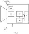
- Figure 6 schematically shows by way of example a system 602 adapted to perform background light subtraction in an IR illuminated image depicting a scene.
- the functionality of the system will now be described in conjunction with figure 7 .
- the system 602 comprises a rolling shutter image sensor 606 with a plurality lines of pixels, wherein the rolling shutter image sensor during capture of an image reads out pixel data from one line of pixels at a time.
- the rolling shutter image sensor 606 is thus provided S702.
- the system 602 further comprises an IR light source 604 configured to be turned on and off, wherein when being turned on, the IR light is configured to illuminate the scene.
- the IR light is thus provided S704.
- IR is electromagnetic radiation (EMR) with wavelengths longer than those of visible light. It is therefore invisible to the human eye. IR is generally understood to encompass wavelengths from around 1 millimetre (300 GHz) to the nominal red edge of the visible spectrum, around 700 nanometres (430 THz). Infrared light sources may be used to augment the available ambient light for conversion by night vision devices, increasing in-the-dark visibility without actually using a visible light source.
- the IR light source and thus the method 700 shown in figure 7 , is only used when a determined luminosity value of natural light in the scene does not exceed a threshold luminosity.
- Any type of light sensor e.g., a light meter, a lux meter, or a photometer
- the threshold luminosity may be configured based on the use case and the parameters of the rolling shutter image sensor.
- the threshold luminosity may be set to e.g., 2 lux, 1 lux, 0.5 lux, etc.
- Any suitable IR light source 604 may be used, such as bulbs, lamps or diodes.
- the system 602 further comprises an IR light controlling unit 608 configured to change S706 an on-off status of the IR light a plurality of times while capturing an image with the rolling shutter image sensor.
- the rolling shutter image sensor 606 is configured for capturing S708 two or more image frames (as exemplified in figures 2-3 ), wherein the rolling shutter image sensor being configured to read out image data to the two or more image frames interleaved in time. Consequently, each image frame will comprise a first set of lines of pixels comprising image data captured with the IR light turned on and a second set of lines of pixels comprising image data captured with the IR light turned off.
- the system 602 further comprises an image stitching unit 610 configured to create S710 (e.g., crop and stitch), as exemplified in figure 4-5 , an IR-illuminated image based at least in part on the first set of lines of the two or more image frames and to create S712 a non-IR-illuminated image based at least in part on the second set of lines of the two or more image frames.
- the image stitching unit 610 may further be configured to subtract S714 background light from the IR-illuminated image using pixel values in the non-IR-illuminated image, thereby creating a modified IR-illuminated image (as shown in figure 1 as reference 106).
- the system 602 further comprises an image analysis unit 612 configured to detect a license plate in the modified IR illuminated image.
- the rolling shutter image sensor may be provided in a camera 600 capturing a scene comprising a road.
- the system 602 further comprises a wireless transmitter 614. It can be used to transmit data such as the modified IR-illumined image or any detected license plates or other data from analysing the modified IR-illumined image.
- the data may be transmitted for storage, or further analysis at a server.
- the data may be received by a human operator trained to act on the data.
- the system 602 may in examples be implemented in a single device such as a camera 600.
- some or all of the different components (modules, units, etc.,) 606, 608, 610, 612, 614 may be implemented in a server or in the cloud.
- the device (camera, server, etc.,) implementing the components 606, 608, 610, 612, 614 may comprise circuitry which is configured to implement the components 606, 608, 610, 612, 614 and, more specifically, their functionality.
- the described features in the system 602 can be implemented advantageously in one or more computer programs that are executable on a programmable system including at least one programmable processor coupled to receive data and instructions from, and to transmit data and instructions to, a data storage system, at least one input device such as a camera, and at least one output device such as a display.
- Suitable processors for the execution of a program of instructions include, by way of example, both general and special purpose microprocessors, and the sole processor or one of multiple processors or cores, of any kind of computer.
- the processors can be supplemented by, or incorporated in, ASICs (application-specific integrated circuits).
- the image analysis unit 612 may be configured to detect road signs.
- the output from the image analysis unit may be used to control a vehicle that the camera 600 is mounted to.
Landscapes
- Engineering & Computer Science (AREA)
- Multimedia (AREA)
- Signal Processing (AREA)
- Physics & Mathematics (AREA)
- Theoretical Computer Science (AREA)
- General Physics & Mathematics (AREA)
- Toxicology (AREA)
- Health & Medical Sciences (AREA)
- Spectroscopy & Molecular Physics (AREA)
- Studio Devices (AREA)
- Image Processing (AREA)
- Transforming Light Signals Into Electric Signals (AREA)
- Image Analysis (AREA)
- Image Input (AREA)
- Apparatus For Radiation Diagnosis (AREA)
- Endoscopes (AREA)
Claims (12)
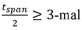
- Verfahren zum Durchführen von Hintergrundlichtsubtraktion in einem mit Infrarot bzw. IR beleuchteten Bild, das eine Szene darstellt, wobei das Verfahren Folgendes umfasst:Bereitstellen (S702) eines Rolling Shutter-Bildsensors mit einer Vielzahl von Pixelzeilen, wobei der Rolling Shutter-Bildsensor während der Aufnahme eines Bildes Pixeldaten aus einer Pixelzeile zurzeit ausliest;Bereitstellen (S704) einer IR-Lichtquelle (206, 306, 604), die dafür ausgelegt ist, ein- und ausgeschaltet zu werden, wobei das IR-Licht dafür ausgelegt ist, wenn eingeschaltet, die Szene zu beleuchten;mehrmaliges Ändern (S706) eines Ein-/Aus-Status (206) der IR-Lichtquelle während Aufnehmens eines Bildes mit dem Rolling Shutter-Bildsensor;Aufnehmen (S708) von drei Bildframes (302, 304, 306) unter Verwendung des Rolling Shutter-Bildsensors, wobei die drei Bildframes in einer chronologischen Reihenfolge aufgenommen werden und einen ersten Bildframe (302) in chronologischer Reihenfolge und einen letzten Bildframe (306) in einer chronologischen Reihenfolge umfassen, wobei der Rolling Shutter-Bildsensor dafür ausgelegt ist, Bilddaten zeitlich verschachtelt an die drei Bildframes auszulesen, so dass Auslesen einer ersten Pixelzeile für den letzten Bildframe vor Auslesen einer letzten Pixelzeile zum ersten Bildframe durchgeführt wird, wobei jeder Bildframe Folgendes umfasst:einen ersten Satz von Pixelzeilen, der nur bei eingeschaltetem IR-Licht belichtet wird;einen zweiten Satz von Pixelzeilen, der nur bei ausgeschaltetem IR-Licht belichtet wird;einen dritten Satz von Pixelzeilen, der sowohl bei ein- als auch ausgeschaltetem IR-Licht belichtet wird;Erschaffen (S710) eines IR-beleuchteten Bildes (102), wobei nur der erste Satz von Zeilen der drei Frames verwendet wird;Erschaffen (S712) eines nicht-IR-beleuchteten Bildes (104), wobei nur der zweite Satz von Zeilen der drei Bildframes verwendet wird;Subtrahieren (S714) von Hintergrundlicht von dem IR-beleuchteten Bild unter Verwendung von Pixelwerten in dem nicht-IR-beleuchteten Bild, wodurch ein modifiziertes IR-beleuchtetes Bild (106) geschaffen wird,wobei der Schritt des Wechselns eines Ein-Aus-Status der IR-Leuchte Abschließen eines Ein-Aus-Zyklus der IR-Leuchte während einer zweiten Zeitspanne, t span_2, (310) umfasst, wobei die IR-Leuchte während einer ersten Hälfte der zweiten Zeitspanne eingeschaltet und während einer zweiten Hälfte der zweiten Zeitspanne ausgeschaltet ist und wobei
 wobei der Schritt des Aufnehmens von drei Bildframes Folgendes umfasst:Aufnehmen eines ersten Bildframes (302), eines zweiten Bildframes (304) und eines dritten Bildframes (306);Auslesen, durch den Rolling Shutter-Bildsensor, einer ersten Pixelzeile (212) für den ersten Bildframe (302) zu einem ersten Zeitpunkt, t;Auslesen, durch den Rolling Shutter-Bildsensor, der ersten Pixelzeile (212) für den zweiten Bildframe (304) bei
 Auslesen, durch den Rolling Shutter-Bildsensor, der ersten Pixelzeile (212) für den dritten Bildframe (306) bei
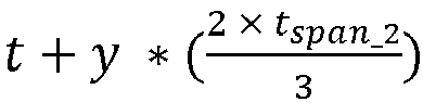 wobei x und y positive natürliche Zahlen sind.
 - Verfahren nach Anspruch 1, wobei der Schritt des Subtrahierens, für jede Pixelkoordinate mindestens eines Teilsatzes von Pixelkoordinaten (108, 110) im nicht-IR-beleuchteten Bild, Subtrahieren des Pixelwerts an der Pixelkoordinate im nicht-IR-beleuchteten Bild vom Pixelwert an einer korrespondierenden Pixelkoordinate in dem IR-beleuchteten Bild, umfasst.
- Verfahren nach Anspruch 2, ferner umfassend den Schritt von Auswählen des Teilsatzes von Pixelkoordinaten auf der Grundlage der Luminosität der Pixelwerte im nicht-IR-beleuchteten Bild.
- Verfahren nach Anspruch 1, wobei der Schritt des Subtrahierens umfasst: für jede Pixelkoordinate von mindestens einem Teilsatz von Pixelkoordinaten (108, 110) im nicht-IR-beleuchteten Bild, Multiplizieren des Pixelwerts an der Pixelkoordinate im nicht-IR-beleuchteten Bild mit einem Gewichtswert, und Subtrahieren des gewichteten Pixelwerts an der Pixelkoordinate im nicht-IR-beleuchteten Bild vom Pixelwert an einer korrespondierenden Pixelkoordinate im IR-beleuchteten Bild.
- Verfahren nach einem der Ansprüche 1-4, umfassend einen Anfangsschritt von Bestimmen eines Luminositätswerts von natürlichem Licht in der Szene, wobei, bei Bestimmen, dass der Luminositätswert eine Schwellenluminosität überschreitet, das Verfahren abgebrochen wird, und bei Bestimmen, dass der Luminositätswert eine Schwellenluminosität nicht überschreitet, das Verfahren weitergeführt wird.
- Verfahren nach einem der Ansprüche 1-5, wobei der Rolling Shutter-Bildsensor dafür ausgelegt ist, für alle Pixelzeilen eine selbe Belichtungszeit aufzuweisen.
- Verfahren nach einem der Ansprüche 1-6, ferner umfassend den Schritt von:
Detektieren eines Nummernschilds in dem modifizierten IR-beleuchteten Bild. - Verfahren nach einem der Ansprüche 1-7, wobei der Rolling Shutter-Bildsensor in einer Kamera vorgesehen ist, die eine Szene aufnimmt, die eine Straße umfasst.
- Verfahren nach einem der Ansprüche 1-8, wobei x=1 und y=1 ist.
- System (602), umfassend:einen Rolling Shutter-Bildsensor (606) mit einer Vielzahl von Pixelzeilen, wobei der Rolling Shutter-Bildsensor während der Aufnahme eines Bildes Pixeldaten aus einer Pixelzeile zurzeit ausliest;eine IR-Leuchte (604), die dafür ausgelegt ist, ein- und ausgeschaltet zu werden, wobei die IR-Leuchte dafür ausgelegt ist, wenn eingeschaltet, die Szene zu beleuchten;eine IR-Leuchte-Steuerungseinheit (608), ausgelegt zum mehrmaligen Ändern (S706) eines Ein-/Aus-Status der IR-Leuchte während Aufnehmens eines Bildes mit dem Rolling Shutter-Bildsensor;wobei der Rolling Shutter-Bildsensor ausgelegt ist zum Aufnehmen (S708) von drei Bildframes (302, 304, 306), wobei die drei Bildframes in einer chronologischen Reihenfolge aufgenommen werden und einen ersten Bildframe in chronologischer Reihenfolge und einen letzten Bildframe in einer chronologischen Reihenfolge umfassen, wobei der Rolling Shutter-Bildsensor dafür ausgestaltet ist, Bilddaten zeitlich verschachtelt an die drei Bildframes auszulesen, so dass Auslesen einer ersten Pixelzeile für den letzten Bildframe vor Auslesen einer letzten Pixelzeile zum ersten Bildframe durchgeführt wird, wobei jeder Bildframe Folgendes umfasst:einen ersten Satz von Pixelzeilen, die nur bei eingeschalteter IR-Leuchte belichtet werden;einen zweiten Satz von Pixelzeilen, die nur bei ausgeschalteter IR-Leuchte belichtet werden;einen dritten Satz von Pixelzeilen, der sowohl bei ein- als auch ausgeschalteter IR-Leuchte belichtet wird;wobei die Vorrichtung ferner eine Bildzusammensetzeinheit (610) umfasst, die ausgelegt ist zum:Erschaffen (S710) eines IR-beleuchteten Bildes, wobei nur der erste Satz von Zeilen der drei Bildframes verwendet wird;Erschaffen (S712) eines nicht-IR-beleuchteten Bildes, wobei nur der zweite Satz von Zeilen der drei Bildframes verwendet wird; undSubtrahieren (S714) von Hintergrundlicht von dem IR-beleuchteten Bild unter Verwendung von Pixelwerten in dem nicht-IR-beleuchteten Bild, wodurch ein modifiziertes IR-beleuchtetes Bild geschaffen wird,wobei die IR-Leuchte-Steuerungseinheit ausgelegt ist zum Abschließen eines Ein-Aus-Zyklus der IR-Leuchte während einer zweiten Zeitspanne, t span_2, (310), wobei
 wobei der Rolling Shutter-Bildsensor ausgelegt ist zum:Aufnehmen eines ersten Bildframes (302), eines zweiten Bildframes (304) und eines dritten Bildframes (306);Auslesen einer ersten Pixelzeile (212) für den ersten Bildframe (302) zu einem ersten Zeitpunkt, t;Auslesen der ersten Pixelzeile (212) für den zweiten Bildframe (304) bei t + x *
 Auslesen der ersten Pixelzeile (212) für den dritten Bildframe (306) bei t + y * (
 wobei x und y positive natürliche Zahlen sind.
 - System nach Anspruch 10, ferner umfassend:
eine Bildanalyseeinheit (612), die ausgelegt ist zum Detektieren eines Nummernschilds im modifizierten IR-beleuchteten Bild. - Nicht-transitorisches computerlesbares Speicherungsmedium, das darauf Anweisungen gespeichert hat zum Implementieren des Verfahrens nach einem der Ansprüche 1-9, wenn auf einer Vorrichtung ausgeführt, die Verarbeitungsfähigkeiten aufweist.
Priority Applications (6)
| Application Number | Priority Date | Filing Date | Title |
|---|---|---|---|
| EP23154105.3A EP4412192B1 (de) | 2023-01-31 | 2023-01-31 | Hintergrundlichtsubtraktion für infrarotbilder |
| KR1020230180813A KR102868442B1 (ko) | 2023-01-31 | 2023-12-13 | 적외선 이미지의 배경광 제거 방법 |
| TW113101160A TWI904542B (zh) | 2023-01-31 | 2024-01-11 | 執行用於紅外線影像之背景光減除之方法及相關之系統及非暫時性電腦可讀儲存媒體 |
| US18/414,910 US12375827B2 (en) | 2023-01-31 | 2024-01-17 | Background light subtraction for infra-red images |
| JP2024008513A JP7784456B2 (ja) | 2023-01-31 | 2024-01-24 | 赤外画像のための背景光減算 |
| CN202410117077.0A CN118433555B (zh) | 2023-01-31 | 2024-01-26 | 用于红外图像的背景光消减 |
Applications Claiming Priority (1)
| Application Number | Priority Date | Filing Date | Title |
|---|---|---|---|
| EP23154105.3A EP4412192B1 (de) | 2023-01-31 | 2023-01-31 | Hintergrundlichtsubtraktion für infrarotbilder |
Publications (3)
| Publication Number | Publication Date |
|---|---|
| EP4412192A1 EP4412192A1 (de) | 2024-08-07 |
| EP4412192B1 true EP4412192B1 (de) | 2025-05-28 |
| EP4412192C0 EP4412192C0 (de) | 2025-05-28 |
Family
ID=85150172
Family Applications (1)
| Application Number | Title | Priority Date | Filing Date |
|---|---|---|---|
| EP23154105.3A Active EP4412192B1 (de) | 2023-01-31 | 2023-01-31 | Hintergrundlichtsubtraktion für infrarotbilder |
Country Status (6)
| Country | Link |
|---|---|
| US (1) | US12375827B2 (de) |
| EP (1) | EP4412192B1 (de) |
| JP (1) | JP7784456B2 (de) |
| KR (1) | KR102868442B1 (de) |
| CN (1) | CN118433555B (de) |
| TW (1) | TWI904542B (de) |
Family Cites Families (28)
| Publication number | Priority date | Publication date | Assignee | Title |
|---|---|---|---|---|
| DE112007003473B4 (de) | 2007-05-07 | 2017-04-06 | Fujitsu Limited | Nachtsichtgerät |
| US8289300B2 (en) * | 2009-07-17 | 2012-10-16 | Microsoft Corporation | Ambient correction in rolling image capture system |
| EP3588939B1 (de) * | 2010-10-31 | 2023-10-18 | Mobileye Vision Technologies Ltd. | Gebündelte nachtsicht- und andere fahrerassistenzsysteme mithilfe von nahinfrarotbeleuchtung und einem rolling shutter |
| US9083905B2 (en) | 2011-04-26 | 2015-07-14 | Semiconductor Components Industries, Llc | Structured light imaging system |
| CN103781398B (zh) * | 2011-11-07 | 2016-08-17 | 奥林巴斯株式会社 | 摄像装置 |
| EP2938065A1 (de) * | 2014-04-23 | 2015-10-28 | Thomson Licensing | Verfahren und Vorrichtung zur Erfassung einer Szene unter verschiedenen Beleuchtungskonfigurationen |
| JP6471953B2 (ja) * | 2014-05-23 | 2019-02-20 | パナソニックIpマネジメント株式会社 | 撮像装置、撮像システム、及び撮像方法 |
| US9704201B2 (en) * | 2014-07-30 | 2017-07-11 | Conduent Business Services, Llc | Method and system for detecting uninsured motor vehicles |
| WO2016093070A1 (ja) * | 2014-12-10 | 2016-06-16 | ソニー株式会社 | 撮像装置、撮像方法、およびプログラム、並びに画像処理装置 |
| US9736405B2 (en) * | 2015-01-29 | 2017-08-15 | Altasens, Inc. | Global shutter image sensor having extremely fine pitch |
| EP3113477B1 (de) * | 2015-06-30 | 2017-08-02 | Axis AB | Überwachungskamera |
| CN105306796A (zh) * | 2015-10-10 | 2016-02-03 | 安霸半导体技术(上海)有限公司 | 具有定期红外照明和全局快门cmos传感器的夜视设备 |
| JP6700731B2 (ja) * | 2015-11-13 | 2020-05-27 | キヤノン株式会社 | 投影装置および投影システム |
| US9800807B2 (en) * | 2016-02-26 | 2017-10-24 | Intel Corporation | Image sensor operation for shutter modulation and high dynamic range |
| WO2018145030A1 (en) * | 2017-02-06 | 2018-08-09 | Intuitive Surgical Operations, Inc. | System and method for extracting multiple feeds from a rolling-shutter sensor |
| US11375174B2 (en) | 2017-11-27 | 2022-06-28 | Nlight, Inc. | System and method of reducing ambient background light in a pulse-illuminated image |
| US10609298B2 (en) * | 2018-02-06 | 2020-03-31 | Google Llc | Adaptive infrared illumination for exposure correction |
| WO2020069034A1 (en) * | 2018-09-26 | 2020-04-02 | Zoox, Inc. | Image scan line timestamping |
| CN110248105B (zh) | 2018-12-10 | 2020-12-08 | 浙江大华技术股份有限公司 | 一种图像处理方法、摄像机及计算机存储介质 |
| CN109886896B (zh) * | 2019-02-28 | 2021-04-27 | 闽江学院 | 一种蓝色车牌分割与矫正方法 |
| CN110493492B (zh) * | 2019-05-31 | 2021-02-26 | 杭州海康威视数字技术股份有限公司 | 图像采集装置及图像采集方法 |
| US11196937B2 (en) | 2019-11-25 | 2021-12-07 | Qualcomm Incorporated | High frame rate in high dynamic range processing |
| CN112995441B (zh) | 2019-12-12 | 2024-05-28 | 超威半导体(上海)有限公司 | 用于对象识别的处理装置和处理方法 |
| EP3839880A1 (de) * | 2019-12-20 | 2021-06-23 | Koninklijke Philips N.V. | System zur durchführung einer umgebungslichtbildkorrektur |
| CN111526303B (zh) | 2020-04-30 | 2022-05-24 | 长春长光辰芯光电技术有限公司 | 结构光成像中去除背景光的方法 |
| CN114079709B (zh) * | 2020-08-07 | 2024-04-12 | 安霸国际有限合伙企业 | 用于卷帘式快门传感器的驱动器机构以获取结构光图案 |
| JP7609611B2 (ja) * | 2020-11-20 | 2025-01-07 | ソニー・オリンパスメディカルソリューションズ株式会社 | 光源制御装置及び医療用観察システム |
| CN213637953U (zh) | 2020-12-16 | 2021-07-06 | 珠海市深九鼎光电科技有限公司 | 一种摄像头模组 |
-
2023
- 2023-01-31 EP EP23154105.3A patent/EP4412192B1/de active Active
- 2023-12-13 KR KR1020230180813A patent/KR102868442B1/ko active Active
-
2024
- 2024-01-11 TW TW113101160A patent/TWI904542B/zh active
- 2024-01-17 US US18/414,910 patent/US12375827B2/en active Active
- 2024-01-24 JP JP2024008513A patent/JP7784456B2/ja active Active
- 2024-01-26 CN CN202410117077.0A patent/CN118433555B/zh active Active
Also Published As
| Publication number | Publication date |
|---|---|
| US20240259691A1 (en) | 2024-08-01 |
| JP7784456B2 (ja) | 2025-12-11 |
| CN118433555B (zh) | 2026-03-03 |
| JP2024109072A (ja) | 2024-08-13 |
| KR20240120637A (ko) | 2024-08-07 |
| EP4412192A1 (de) | 2024-08-07 |
| KR102868442B1 (ko) | 2025-10-02 |
| CN118433555A (zh) | 2024-08-02 |
| US12375827B2 (en) | 2025-07-29 |
| EP4412192C0 (de) | 2025-05-28 |
| TWI904542B (zh) | 2025-11-11 |
| TW202507660A (zh) | 2025-02-16 |
Similar Documents
| Publication | Publication Date | Title |
|---|---|---|
| CN114422724B (zh) | 分束扩展的动态范围图像捕获系统 | |
| US20200265258A1 (en) | Systems and methods for locating a retroreflective object in a digital image | |
| US8723980B2 (en) | Image processing system and image acquisition method | |
| CN110505377B (zh) | 图像融合设备和方法 | |
| CN110557574A (zh) | 高动态范围上可见光通信源的检测 | |
| JP2020529159A (ja) | 多重化高ダイナミックレンジ画像 | |
| US9105105B2 (en) | Imaging device, imaging system, and imaging method utilizing white balance correction | |
| CN110493496A (zh) | 图像采集装置及方法 | |
| CN110493537B (zh) | 图像采集装置及图像采集方法 | |
| CN110493533B (zh) | 图像采集装置及图像采集方法 | |
| EP4412192B1 (de) | Hintergrundlichtsubtraktion für infrarotbilder | |
| JP2004229034A (ja) | 赤外線照明内蔵型デイナイトカメラ | |
| US9832398B2 (en) | Camera system, especially for a vehicle, and method for ascertaining image information of a signal source pulsed as a function of time | |
| US20220103769A1 (en) | An Imaging Device and a Method of Enabling Rolling Shutter Image Sensor to Function as Global Shutter | |
| JP6525723B2 (ja) | 撮像装置及びその制御方法、プログラム、並びに記憶媒体 | |
| JP4677924B2 (ja) | 撮影システム、動画像処理方法および動画像処理装置 | |
| Leznik et al. | Optimization of demanding scenarios in CMS and image quality criteria | |
| KR101691043B1 (ko) | 적외선을 이용하여 야간 컬러영상을 구현하는 폐쇄회로 텔레비전 카메라 | |
| CN119136066A (zh) | 行车记录图像的生成方法、装置、设备以及存储介质 | |
| CN118890420A (zh) | 一种基于双目摄像头的全亮度场景输出视频流的方法 | |
| JP2021044667A (ja) | 露光制御装置 | |
| JP2016200742A (ja) | 撮像装置 | |
| CN117835068A (zh) | 一种用于红绿灯识别的摄像机控制方法、设备及存储介质 | |
| CN112995581A (zh) | 一种视频监控方法及系统 |
Legal Events
| Date | Code | Title | Description |
|---|---|---|---|
| PUAI | Public reference made under article 153(3) epc to a published international application that has entered the european phase |
Free format text: ORIGINAL CODE: 0009012 |
|
| STAA | Information on the status of an ep patent application or granted ep patent |
Free format text: STATUS: EXAMINATION IS IN PROGRESS |
|
| 17P | Request for examination filed |
Effective date: 20230629 |
|
| AK | Designated contracting states |
Kind code of ref document: A1 Designated state(s): AL AT BE BG CH CY CZ DE DK EE ES FI FR GB GR HR HU IE IS IT LI LT LU LV MC ME MK MT NL NO PL PT RO RS SE SI SK SM TR |
|
| GRAP | Despatch of communication of intention to grant a patent |
Free format text: ORIGINAL CODE: EPIDOSNIGR1 |
|
| STAA | Information on the status of an ep patent application or granted ep patent |
Free format text: STATUS: GRANT OF PATENT IS INTENDED |
|
| INTG | Intention to grant announced |
Effective date: 20250311 |
|
| GRAS | Grant fee paid |
Free format text: ORIGINAL CODE: EPIDOSNIGR3 |
|
| GRAA | (expected) grant |
Free format text: ORIGINAL CODE: 0009210 |
|
| STAA | Information on the status of an ep patent application or granted ep patent |
Free format text: STATUS: THE PATENT HAS BEEN GRANTED |
|
| AK | Designated contracting states |
Kind code of ref document: B1 Designated state(s): AL AT BE BG CH CY CZ DE DK EE ES FI FR GB GR HR HU IE IS IT LI LT LU LV MC ME MK MT NL NO PL PT RO RS SE SI SK SM TR |
|
| REG | Reference to a national code |
Ref country code: GB Ref legal event code: FG4D |
|
| REG | Reference to a national code |
Ref country code: CH Ref legal event code: EP |
|
| REG | Reference to a national code |
Ref country code: IE Ref legal event code: FG4D Ref country code: DE Ref legal event code: R096 Ref document number: 602023003649 Country of ref document: DE |
|
| U01 | Request for unitary effect filed |
Effective date: 20250528 |
|
| U07 | Unitary effect registered |
Designated state(s): AT BE BG DE DK EE FI FR IT LT LU LV MT NL PT RO SE SI Effective date: 20250605 |
|
| PG25 | Lapsed in a contracting state [announced via postgrant information from national office to epo] |
Ref country code: ES Free format text: LAPSE BECAUSE OF FAILURE TO SUBMIT A TRANSLATION OF THE DESCRIPTION OR TO PAY THE FEE WITHIN THE PRESCRIBED TIME-LIMIT Effective date: 20250528 |
|
| PG25 | Lapsed in a contracting state [announced via postgrant information from national office to epo] |
Ref country code: GR Free format text: LAPSE BECAUSE OF FAILURE TO SUBMIT A TRANSLATION OF THE DESCRIPTION OR TO PAY THE FEE WITHIN THE PRESCRIBED TIME-LIMIT Effective date: 20250829 Ref country code: NO Free format text: LAPSE BECAUSE OF FAILURE TO SUBMIT A TRANSLATION OF THE DESCRIPTION OR TO PAY THE FEE WITHIN THE PRESCRIBED TIME-LIMIT Effective date: 20250828 |
|
| PG25 | Lapsed in a contracting state [announced via postgrant information from national office to epo] |
Ref country code: PL Free format text: LAPSE BECAUSE OF FAILURE TO SUBMIT A TRANSLATION OF THE DESCRIPTION OR TO PAY THE FEE WITHIN THE PRESCRIBED TIME-LIMIT Effective date: 20250528 |
|
| PG25 | Lapsed in a contracting state [announced via postgrant information from national office to epo] |
Ref country code: HR Free format text: LAPSE BECAUSE OF FAILURE TO SUBMIT A TRANSLATION OF THE DESCRIPTION OR TO PAY THE FEE WITHIN THE PRESCRIBED TIME-LIMIT Effective date: 20250528 |
|
| PG25 | Lapsed in a contracting state [announced via postgrant information from national office to epo] |
Ref country code: RS Free format text: LAPSE BECAUSE OF FAILURE TO SUBMIT A TRANSLATION OF THE DESCRIPTION OR TO PAY THE FEE WITHIN THE PRESCRIBED TIME-LIMIT Effective date: 20250828 |
|
| PG25 | Lapsed in a contracting state [announced via postgrant information from national office to epo] |
Ref country code: IS Free format text: LAPSE BECAUSE OF FAILURE TO SUBMIT A TRANSLATION OF THE DESCRIPTION OR TO PAY THE FEE WITHIN THE PRESCRIBED TIME-LIMIT Effective date: 20250928 |
|
| PG25 | Lapsed in a contracting state [announced via postgrant information from national office to epo] |
Ref country code: SM Free format text: LAPSE BECAUSE OF FAILURE TO SUBMIT A TRANSLATION OF THE DESCRIPTION OR TO PAY THE FEE WITHIN THE PRESCRIBED TIME-LIMIT Effective date: 20250528 |
|
| PG25 | Lapsed in a contracting state [announced via postgrant information from national office to epo] |
Ref country code: CZ Free format text: LAPSE BECAUSE OF FAILURE TO SUBMIT A TRANSLATION OF THE DESCRIPTION OR TO PAY THE FEE WITHIN THE PRESCRIBED TIME-LIMIT Effective date: 20250528 |
|
| U20 | Renewal fee for the european patent with unitary effect paid |
Year of fee payment: 4 Effective date: 20251217 |
|
| PG25 | Lapsed in a contracting state [announced via postgrant information from national office to epo] |
Ref country code: SK Free format text: LAPSE BECAUSE OF FAILURE TO SUBMIT A TRANSLATION OF THE DESCRIPTION OR TO PAY THE FEE WITHIN THE PRESCRIBED TIME-LIMIT Effective date: 20250528 |
|
| PLBE | No opposition filed within time limit |
Free format text: ORIGINAL CODE: 0009261 |
|
| STAA | Information on the status of an ep patent application or granted ep patent |
Free format text: STATUS: NO OPPOSITION FILED WITHIN TIME LIMIT |
|
| REG | Reference to a national code |
Ref country code: CH Ref legal event code: L10 Free format text: ST27 STATUS EVENT CODE: U-0-0-L10-L00 (AS PROVIDED BY THE NATIONAL OFFICE) Effective date: 20260409 |