EP4414282A1 - Verschlussvorrichtung mit kappe mit vergrösserter innenfläche - Google Patents
Verschlussvorrichtung mit kappe mit vergrösserter innenfläche Download PDFInfo
- Publication number
- EP4414282A1 EP4414282A1 EP23155929.5A EP23155929A EP4414282A1 EP 4414282 A1 EP4414282 A1 EP 4414282A1 EP 23155929 A EP23155929 A EP 23155929A EP 4414282 A1 EP4414282 A1 EP 4414282A1
- Authority
- EP
- European Patent Office
- Prior art keywords
- lid
- closure device
- protrusions
- internal side
- cap
- Prior art date
- Legal status (The legal status is an assumption and is not a legal conclusion. Google has not performed a legal analysis and makes no representation as to the accuracy of the status listed.)
- Withdrawn
Links
Images





Classifications
-
- B—PERFORMING OPERATIONS; TRANSPORTING
- B65—CONVEYING; PACKING; STORING; HANDLING THIN OR FILAMENTARY MATERIAL
- B65D—CONTAINERS FOR STORAGE OR TRANSPORT OF ARTICLES OR MATERIALS, e.g. BAGS, BARRELS, BOTTLES, BOXES, CANS, CARTONS, CRATES, DRUMS, JARS, TANKS, HOPPERS, FORWARDING CONTAINERS; ACCESSORIES, CLOSURES, OR FITTINGS THEREFOR; PACKAGING ELEMENTS; PACKAGES
- B65D55/00—Accessories for container closures not otherwise provided for
- B65D55/16—Devices preventing loss of removable closure members
-
- B—PERFORMING OPERATIONS; TRANSPORTING
- B65—CONVEYING; PACKING; STORING; HANDLING THIN OR FILAMENTARY MATERIAL
- B65D—CONTAINERS FOR STORAGE OR TRANSPORT OF ARTICLES OR MATERIALS, e.g. BAGS, BARRELS, BOTTLES, BOXES, CANS, CARTONS, CRATES, DRUMS, JARS, TANKS, HOPPERS, FORWARDING CONTAINERS; ACCESSORIES, CLOSURES, OR FITTINGS THEREFOR; PACKAGING ELEMENTS; PACKAGES
- B65D5/00—Rigid or semi-rigid containers of polygonal cross-section, e.g. boxes, cartons or trays, formed by folding or erecting one or more blanks made of paper
- B65D5/42—Details of containers or of foldable or erectable container blanks
- B65D5/72—Contents-dispensing means
- B65D5/74—Spouts
- B65D5/746—Spouts formed separately from the container
-
- B—PERFORMING OPERATIONS; TRANSPORTING
- B65—CONVEYING; PACKING; STORING; HANDLING THIN OR FILAMENTARY MATERIAL
- B65D—CONTAINERS FOR STORAGE OR TRANSPORT OF ARTICLES OR MATERIALS, e.g. BAGS, BARRELS, BOTTLES, BOXES, CANS, CARTONS, CRATES, DRUMS, JARS, TANKS, HOPPERS, FORWARDING CONTAINERS; ACCESSORIES, CLOSURES, OR FITTINGS THEREFOR; PACKAGING ELEMENTS; PACKAGES
- B65D51/00—Closures not otherwise provided for
- B65D51/24—Closures not otherwise provided for combined or co-operating with auxiliary devices for non-closing purposes
Definitions
- the present invention relates to a closure device comprising a pour spout with a through-opening and a cap which has an increased internal surface area.
- the pour spout can be fixed to an outer surface of a container.
- the present invention relates to a closure device were the cap is attached to the pour spout via a hinged portion for retaining the cap in an up-right position to the pour spout when the cap is opened, and where the cap comprises structural protrusions on the side of the cap facing the pour spout through-opening when the cap is closed.
- the structural protrusions are for retaining a fluid.
- the invention also relates to an assembly comprising a package and the closure device comprising a pour spout with a through-opening and a cap which has an increased internal surface area.
- the present invention relates to a closure device were the cap is attached to the pour spout via a hinged portion for retaining the cap in an up-right position to the pour spout when the cap is opened, and where the cap comprises structural protrusions on the side of the cap facing the pour spout through-opening when the cap is closed.
- a package or carton is typically produced from a laminate packaging material, which typically comprises a multi-ply paper or paperboard sheet on which is laminated one or a plurality of barrier layers for holding the pourable product, e.g. a liquid, and/or prevent migration of air and flavour degrading substances through the paper or paperboard sheet.
- a laminate packaging material typically comprises a multi-ply paper or paperboard sheet on which is laminated one or a plurality of barrier layers for holding the pourable product, e.g. a liquid, and/or prevent migration of air and flavour degrading substances through the paper or paperboard sheet.
- a hinge closure device on a package prevents users from misplacing and losing the lid portion when operating the package, e.g. when pouring liquid from the package.
- hinge closure devices are known.
- WO 2019/238988 A1 discloses a collapsible cap for containers comprising a lower ring connected to a cap via an extendable hinged portion.
- the cap portion is configured to stay connected to the container via the hinge portion when the cap is opened.
- US 2012/298,666 A1 discloses a stopper/hinge closure device for a packaging container having a long neck portion. The cap is kept at the side of the container when the cap is in an open position.
- a disadvantage seen with these kind of closure devices is that liquid product may adhere to the internal side of the cap.
- the cap When the cap is in an open position where the cap is retained to the container via a hinge it is likely that any adhered liquid product may start to flow, due to gravity, from the cap and onto for example a hinge portion of the closure device or the container itself.
- the liquid product is a semi viscous or viscous fluid such as drinking yogurt or yogurt which will typically have a tendency to adhere to the cap for a limited time before starting to flow off the cap and onto the hinge portion or the container when the container is resting on a planar surface or handled by a consumer, thus causing undesired spilling of the liquid content of the container.
- An object of the present invention is to provide a closure device comprising a cap which is attached to a pour spout which when in an open position reduces the problems of spilling liquid product.
- a second object of the present invention is to provide a closure device which is simple and economical to manufacture.
- a third object of the present invention is to provide an assembly comprising a package or carton and a closure device which reduces the problems of spilling liquid product.
- the present invention provides a hinged closure device for a paper or paperboard-based container comprising a pour spot and a cap which is possible to flip open.
- a hinge portion is provided between a lid portion and a retainment portion attached to the pour spout to ensure that these parts are kept together even when the cap is flipped and pivoting away from the spout.
- the lid portion is provided with an increased internal surface for retaining fluid when the cap is flipped and pivoted away from the pour spout and while the container is being handled.
- the present invention provides
- the lid portion is operable between a first position in which the lid portion sealingly covers said opening of the pour spout and a second position in which the lid portion is located at least partly at a side of the opening.
- the lid portion further comprising;
- the lid portion further comprising;
- the effect of the increased surface area is enhanced retention of any liquids that may be adhered to the lid internal side for example if the package is shaken before opening the closure device.
- An advantage of the enhanced retention is that it prevents spilling of liquid which typically would flow down from the lid portion and onto the hinge portion, the package or other place when the liquid is affected by gravity.
- the fluid to be retained is semi viscous or viscous and has a centipoise rating between 70-2200 cps.
- poise is the unit for dynamic viscosity.
- centi- is added to provide centipoise abbreviated cps.
- the plurality of protrusions extends 0,5 mm - 10 mm, 0,6 mm - 8 mm, 0,8 mm - 6 mm, 0,9 mm - 4 mm or 1,0 mm - 2 mm perpendicularly from the lid internal side.
- the protrusions may extend substantially perpendicular to the lid internal side.
- the protrusions may also extend at an angle of between 80°-90° or 85°-90° or 86°, 87°, 88° or 89° from the lid internal side.
- the plurality of protrusions covers at least 20%, at least 40%, at least 50%, at least 60%, at least 70%, at least 80% or at least 90% of the area of the lid internal side.
- the plurality of protrusions may for example cover a maximum of 95% of the area of the lid internal side.
- Materials for production of the cap may be saved if only a part of the lid internal side is covered by protrusions.
- the lid internal side comprises
- the central area may retain a droplet of fluid effectively.
- the plurality of protrusions extends further from the lid internal side towards the hinge portion side of the cap creating a wedged shape.
- the plurality of protrusions extends progressively further from the lid internal side towards the hinge portion side of the cap creating a wedged shape.
- Such a wedge shape may help effectively retaining a liquid when the lid portion is in the open second position since the lid portion may then be arranged in a substantially up-right position.
- the wedge shape will then provide a barrier for the liquid to overcome before spilling onto the hinge portion or other undesired places.
- the pour spout comprises;
- the bore seal extends between 1 mm - 15 mm, 1,5 mm - 8 mm, 1,8mm- 6 mm, 1,9 mm - 4 mm, 2,0 mm - 3,0 mm from the lid internal side.
- the bore seal extends further from the lid internal side at the hinge portion side of the cap than the at the opposite side, such as between 2 mm - 6 mm at the hinge portion side and between 1 mm - 3 mm on the opposite side. Or 4 mm - 8 mm at the hinge portion side and between 2 mm - 4 mm on the opposite side or 6 mm - 10 mm at the hinge portion side and between 3 mm -5 mm on the opposite side or 8 mm - 15 mm at the hinge portion side and between 4 mm - 10 mm on the opposite side.
- the bore seal may in this configuration further contribute to the retainment of liquid.
- the plurality of protrusions extends less than 95 %, less than 90 %, less than 80 %, less than 70 %, less than 50 %, less than 40 % or less than 30% of the extent of the bore seal from the lid internal side.
- the liquid may even more effectively be retained within the perimeter of the bore seal and reduce the risk of spilling of liquid, especially when re-closing a previously opened lid portion.
- the plurality of protrusions has a hexagonal honeycomb shape.
- Using a hexagonal or honeycomb shape for the plurality of protrusion allows for efficient use of material due to the sharing of side walls of the protrusions. This results in minimal use of materials and thus a low weight and cost-effective production is achieved.
- the plurality the plurality of protrusions has a triangular, rectangular, circular, oval or square shape.
- the plurality of protrusions are hollow and open at the end distal from the lid internal side.
- capillary effect contributes to retainment of liquid within the plurality of protrusions shown.
- the plurality of protrusions has a pin shape.
- the protrusions may be spaced apart.
- the plurality of protrusions are arranged in concentrical rings.
- the plurality of protrusions are arranged in a spiral or an Archimedean spiral.
- the invention is related to an assembly comprising a paper or paperboard-based package and a closure device as described above.
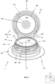
- Fig. 1 shows a first embodiment of the closure device 1.
- the closure device 1 generally comprises a pour spout 100 and a cap 200.
- the pour spout 100 comprises a longitudinal center axis A L defining an axial direction z, a circumferential direction c, and a radial direction r.
- the pour spout 100 comprises an annular neck portion 102 with a first axial end 104 and a second axial end 106.
- the first axial end 104 comprises an annular flange portion 110 extending in the radial direction outwards from the pour spout 100.
- the annular flange portion 110 is for attaching the pour spout 100 to a paper or paper board container 50.
- the neck portion 102 comprises at least one external structure 108 located on the outside surface of the neck portion 102.
- the at least one external structure 108 may be a thread or multiple threads.
- the second axial 106 end is arranged opposite to the first axial end 104.
- the internal perimeter of the second axial end 106 defines a dispensing opening 118 through which contents may be poured or accessed.
- the longitudinal center axis A L runs between the first axial end 104 and the second axial end 106.
- the second axial end 106 may comprise a sealing lip 120 extending in the radial direction r into the dispensing opening.
- the cap 200 may comprise a retainment portion 400 circumferentially arranged around the pour spout 100, a lid portion 300 and a hinge portion 500 for permanently connecting the lid portion 300 to the retainment portion 400.
- the lid portion 300 is open at its bottom end and closed at its top end by an endwall 321, at the outer periphery of which an annular longitudinal/tubular skirt 320 extends axially from the end wall 321.
- the skirt 320 may comprise at least one internal structure 322 for interacting with the external structure 108 of the neck portion 102 for releasably securing the lid portion 300 to the pour spout 100.
- the at least one internal structure 322 may be a thread.
- internal structure 322 and external structure 108 may be envisaged, for example corresponding protrusions and recesses configured for interaction with each other for providing a so-called snap closure.
- Fig. 1 illustrates the closure device 1 in an open position where, when the closure device 1 is attached to a package 50 (not shown in fig. 1 ), the contents within the package 50 can be accessed or poured through the dispensing opening 118.
- the hinge portion 500 may permanently connect the lid portion 300 to the retainment portion 400 and may allow the lid portion to pivot around a pivot axis A P .
- the lid portion 300 may sealingly cover the dispensing opening 118.
- the lid portion 300 is then in a first position (not shown in fig. 1 ).
- Fig. 1 illustrates that the lid portion 300 is pivoting away from the dispensing opening 118 such that the lid portion 300 is located at the side of the pour spout 100.
- the lid portion 300 is not covering the dispensing opening 118 and the lid portion 300 is thus in a second position where the closure device 1 is open.
- the hinge portion 500 allows the lid portion 300 to be operable between the first position and the second position while also being retained to the pour spout 100 by the retainment portion 400.
- the lid portion 300 comprises a lid internal side 301 and a skirt 320 extending from the lid internal side 301.
- the lid internal side 301 faces the dispensing opening 118 when the lid portion 300 covers said dispensing opening 118, i.e. when the lid portion 300 is in the first position.
- the lid internal side 301 may comprise an annular longitudinal bore seal 340 that extends axially from the lid internal side 301.
- the bore seal 340 is configured concentrically and within the skirt 320.
- the bore seal is circular and defines a perimeter 342.
- the bore seal 340 is configured to interact with the sealing lip 120 when the lid portion 300 is in the first position for providing a sealing of the dispensing opening 118 such that liquid content will not pass therethrough. As shown in fig. 1 the bore seal 340 extends the same height from the lid internal side 301 around the entire bore seal 340.
- the lid internal side 301 further comprises a plurality of protrusions 310 extending outwards from the lid internal side 301.
- the plurality of protrusions 310 covers an internal area portion 302 of the lid internal side 301. As shown in fig. 1 the plurality of protrusions 310 may cover the area within the perimeter 342.
- the plurality of protrusions 310 may extend an equal length of the bore seal 340. Further the plurality of protrusions 310 may extend to the same length over the entire area 302 they cover. However, it is also envisaged that the plurality of protrusions 310 may extend to a varying extent over the area they cover. This will be explained in further detail below.
- the plurality of protrusions 310 may be hollow and open at the end distal from the lid internal side 301.
- the plurality of protrusions 310 shown in fig. 1 displays a hexagonal or honeycomb shape where hexagonal protrusions extend from the lid internal side, the protrusions being closed at the protrusion ends proximal to the lid internal side 301 by said lid internal side 301.
- the plurality of protrusions 310 shown in fig. 1 are arranged adjacent to one another and sharing side walls, while they are open at the end distal from the lid internal side 301.
- the plurality of protrusions 310 provides the lid internal side 301 with an increased surface area compared to a lid internal side which has a smooth surface. The effect of this is that any liquids that is accumulated onto the lid internal side 301 may be retained within the lid portion 300 due to the surface tension of the liquid for a longer period of time than for a smooth surface. A consumer may thus avoid spilling any liquid while the lid portion 300 is in the open position.
- capillary effect contributes to retainment of liquid within the plurality of protrusions shown in fig. 1 .
- Using a hexagonal or honeycomb shape for the plurality of protrusion allows for efficient use of material due to the sharing of side walls of the protrusions. This results in minimal use of materials and thus a low weight and cost-effective production is achieved.
- Fig. 2 shows a front view of the same embodiment as fig. 1 .
- Fig. 3 shows a front view of another embodiment of the closure device 1 where the lid portion displays a plurality of protrusions 310 in the shape of pins.
- the pins are arranged within the perimeter 342 defined by the bore seal 340.
- the pins may extend the same length from the lid internal side 301 as the bore seal 340.
- the pins may be arranged in a pattern of concentrical rings.
- the plurality of protrusions 310 shown in fig. 3 is arranged with space between each individual protrusion.
- the plurality of protrusions 310 arranged as pins also increase surface area in order to retain liquid on the lid internal side 301.
- Fig. 4 shows a front view of an embodiment of the closure device 1, where the plurality of protrusions 310 are of a square shape. Other types of rectangular shapes may also be envisaged.
- Fig. 5 shows a front view of an embodiment of the closure device 1, where the plurality of protrusions 310 are of a triangular shape. Protrusions 310 of an oval shape may also be envisaged.
- Fig. 6 shows a front view of another embodiment of the closure device 1 where the lid portion displays a plurality of protrusions 310 in the shape of pins covering a central area of the lid internal side where an area concentrically outside of the covered central area is free of protrusions 310.
- Fig. 7 shows a side view cut of an embodiment of the closure device 1 where the plurality of protrusions 310 extends less from the lid internal side 301 than the bore seal 340 extends from the lid internal side 301. All shapes of protrusions mentioned herein are suitable for the configuration shown in fig. 7 .
- Fig. 8 shows a side view cut of an embodiment of the closure device 1 where the protrusions 310 extends further from the lid internal side 301 at the side of the lid portion where the hinge portion 500 is located.
- the plurality of protrusions 310 may form a wedge shape. All shapes of protrusions mentioned herein are suitable for the configuration shown in fig. 8 .
- Fig. 9 shows a side view of an embodiment of closure device 1 where the plurality of protrusions 310 extends less from the lid internal side at an internal side central area 305 than the plurality of protrusion 310 located concentrically outside of the internal side central area 305. All shapes of protrusions mentioned herein are suitable for the configuration shown in fig. 9 .
- Fig. 10 shows a side view of an embodiment of the closure device 1 where the bore seal 340 extends more from the lid internal side 301 at the side of the lid portion 300 proximal to the hinge portion 500 than on the side of the lid portion 300 distal to the hinge portion 500.
- FIG. 11 shows an assembly of a package 50 with the closure device 1 attached thereto.
- the lid portion 300 covers the dispensing opening 118 (not shown).
- the lid portion 300 is shown in the closed first position.
- List of references 1 Closure device 50 Package 100 Pour spout 102 Neck portion 104 First axial end 106 Second axial end 108 External structure 110 Annular flange portion 118 Dispensing opening 120 Sealing lip 200 Cap 300 Lid portion 301 Lid internal side 302 Lid internal area 305 Lid internal side central area 310 Protrusions 320 Skirt 321 End wall 322 Internal structure 340 Bore seal 342 Perimeter 400 Retainment portion 500 Hinge portion
Landscapes
- Engineering & Computer Science (AREA)
- Mechanical Engineering (AREA)
- Closures For Containers (AREA)
Priority Applications (3)
| Application Number | Priority Date | Filing Date | Title |
|---|---|---|---|
| EP23155929.5A EP4414282A1 (de) | 2023-02-09 | 2023-02-09 | Verschlussvorrichtung mit kappe mit vergrösserter innenfläche |
| EP24702767.5A EP4662134A1 (de) | 2023-02-09 | 2024-01-30 | Verschlussvorrichtung mit kappe mit vergrösserter innenfläche |
| PCT/EP2024/052216 WO2024165379A1 (en) | 2023-02-09 | 2024-01-30 | Closure device comprising a cap with increased internal surface area |
Applications Claiming Priority (1)
| Application Number | Priority Date | Filing Date | Title |
|---|---|---|---|
| EP23155929.5A EP4414282A1 (de) | 2023-02-09 | 2023-02-09 | Verschlussvorrichtung mit kappe mit vergrösserter innenfläche |
Publications (1)
| Publication Number | Publication Date |
|---|---|
| EP4414282A1 true EP4414282A1 (de) | 2024-08-14 |
Family
ID=85225251
Family Applications (2)
| Application Number | Title | Priority Date | Filing Date |
|---|---|---|---|
| EP23155929.5A Withdrawn EP4414282A1 (de) | 2023-02-09 | 2023-02-09 | Verschlussvorrichtung mit kappe mit vergrösserter innenfläche |
| EP24702767.5A Pending EP4662134A1 (de) | 2023-02-09 | 2024-01-30 | Verschlussvorrichtung mit kappe mit vergrösserter innenfläche |
Family Applications After (1)
| Application Number | Title | Priority Date | Filing Date |
|---|---|---|---|
| EP24702767.5A Pending EP4662134A1 (de) | 2023-02-09 | 2024-01-30 | Verschlussvorrichtung mit kappe mit vergrösserter innenfläche |
Country Status (2)
| Country | Link |
|---|---|
| EP (2) | EP4414282A1 (de) |
| WO (1) | WO2024165379A1 (de) |
Citations (7)
| Publication number | Priority date | Publication date | Assignee | Title |
|---|---|---|---|---|
| EP0204425A2 (de) * | 1985-06-04 | 1986-12-10 | Johnsen & Jorgensen (Plastics) Limited | Behälterverschluss (Zellenabdichtung) |
| US20040182863A1 (en) * | 2003-03-21 | 2004-09-23 | Taylor Dale W. | Blow-molded paint container |
| US20120298666A1 (en) | 2010-01-28 | 2012-11-29 | Si Joong Kwon | Stopper for packaging container |
| WO2019238988A1 (es) | 2018-06-12 | 2019-12-19 | Jose Francisco Gonzalez Sanchez | Tapón abatible para envases |
| DE102021117931A1 (de) * | 2020-07-10 | 2022-01-13 | Rosti Gp Germany Gmbh | Mehrteiliger verschluss |
| FR3120354A1 (fr) * | 2021-03-02 | 2022-09-09 | United Caps France | Bouchon muni d’un doigt de verrouillage |
| CH718664A1 (de) * | 2021-05-26 | 2022-11-30 | Alpla Werke Alwin Lehner Gmbh & Co Kg | Behälterverschluss. |
-
2023
- 2023-02-09 EP EP23155929.5A patent/EP4414282A1/de not_active Withdrawn
-
2024
- 2024-01-30 WO PCT/EP2024/052216 patent/WO2024165379A1/en not_active Ceased
- 2024-01-30 EP EP24702767.5A patent/EP4662134A1/de active Pending
Patent Citations (7)
| Publication number | Priority date | Publication date | Assignee | Title |
|---|---|---|---|---|
| EP0204425A2 (de) * | 1985-06-04 | 1986-12-10 | Johnsen & Jorgensen (Plastics) Limited | Behälterverschluss (Zellenabdichtung) |
| US20040182863A1 (en) * | 2003-03-21 | 2004-09-23 | Taylor Dale W. | Blow-molded paint container |
| US20120298666A1 (en) | 2010-01-28 | 2012-11-29 | Si Joong Kwon | Stopper for packaging container |
| WO2019238988A1 (es) | 2018-06-12 | 2019-12-19 | Jose Francisco Gonzalez Sanchez | Tapón abatible para envases |
| DE102021117931A1 (de) * | 2020-07-10 | 2022-01-13 | Rosti Gp Germany Gmbh | Mehrteiliger verschluss |
| FR3120354A1 (fr) * | 2021-03-02 | 2022-09-09 | United Caps France | Bouchon muni d’un doigt de verrouillage |
| CH718664A1 (de) * | 2021-05-26 | 2022-11-30 | Alpla Werke Alwin Lehner Gmbh & Co Kg | Behälterverschluss. |
Also Published As
| Publication number | Publication date |
|---|---|
| EP4662134A1 (de) | 2025-12-17 |
| WO2024165379A1 (en) | 2024-08-15 |
Similar Documents
| Publication | Publication Date | Title |
|---|---|---|
| EP3854716B1 (de) | Verschlussvorrichtung für eine verpackung auf papier- oder kartonbasis | |
| EP2844610B1 (de) | Behälterverschluss für einen entlüfteten giesstrog einer länglichen öffnung | |
| RU2521396C2 (ru) | Сосуд и способ его изготовления | |
| US20090261152A1 (en) | Container with folding lid | |
| CN101734417B (zh) | 刺穿衬板的可扭弯的封闭件 | |
| CA2866350A1 (en) | Container closure for vented pouring through a curved aperture | |
| CN107074410A (zh) | 分配封闭件 | |
| WO2008091936A2 (en) | Flip top closure assembly for a bottle | |
| US5467879A (en) | Linerless closure and fitment assembly | |
| JP2011246137A (ja) | ヒンジキャップ | |
| JP6533383B2 (ja) | ヒンジキャップ | |
| WO2000016668A1 (en) | Retractable drink spout | |
| US20090283491A1 (en) | Multiple reservoir bottle | |
| EP4414282A1 (de) | Verschlussvorrichtung mit kappe mit vergrösserter innenfläche | |
| JP5000425B2 (ja) | 注出筒を有するプラスチックキャップ | |
| JP7499394B2 (ja) | 油脂容器用注ぎ口 | |
| US7000808B2 (en) | Spout design | |
| JP2021008290A (ja) | 容器用キャップ | |
| JP4840568B2 (ja) | キャップ | |
| CA2485477A1 (en) | Spout closure for liquid packagings | |
| EP4455041A1 (de) | Verschluss für einen behälter und behälter mit einem solchen verschluss | |
| JP4154716B2 (ja) | 液垂れ防止用キャップ | |
| JP3103088U (ja) | 液垂れ防止用キャップ | |
| RU2430868C2 (ru) | Упаковочный контейнер, прежде всего выполненный в виде банки контейнер | |
| US20010030206A1 (en) | One-piece push-pull cap with non-spurting clean top |
Legal Events
| Date | Code | Title | Description |
|---|---|---|---|
| PUAI | Public reference made under article 153(3) epc to a published international application that has entered the european phase |
Free format text: ORIGINAL CODE: 0009012 |
|
| STAA | Information on the status of an ep patent application or granted ep patent |
Free format text: STATUS: THE APPLICATION HAS BEEN PUBLISHED |
|
| AK | Designated contracting states |
Kind code of ref document: A1 Designated state(s): AL AT BE BG CH CY CZ DE DK EE ES FI FR GB GR HR HU IE IS IT LI LT LU LV MC ME MK MT NL NO PL PT RO RS SE SI SK SM TR |
|
| STAA | Information on the status of an ep patent application or granted ep patent |
Free format text: STATUS: THE APPLICATION IS DEEMED TO BE WITHDRAWN |
|
| 18D | Application deemed to be withdrawn |
Effective date: 20250215 |