EP4414539A2 - Machine utilitaire compacte avec système de refroidissement passif - Google Patents
Machine utilitaire compacte avec système de refroidissement passif Download PDFInfo
- Publication number
- EP4414539A2 EP4414539A2 EP24151933.9A EP24151933A EP4414539A2 EP 4414539 A2 EP4414539 A2 EP 4414539A2 EP 24151933 A EP24151933 A EP 24151933A EP 4414539 A2 EP4414539 A2 EP 4414539A2
- Authority
- EP
- European Patent Office
- Prior art keywords
- engine
- engine compartment
- fan
- air
- compact
- Prior art date
- Legal status (The legal status is an assumption and is not a legal conclusion. Google has not performed a legal analysis and makes no representation as to the accuracy of the status listed.)
- Pending
Links
Images


Classifications
-
- F—MECHANICAL ENGINEERING; LIGHTING; HEATING; WEAPONS; BLASTING
- F01—MACHINES OR ENGINES IN GENERAL; ENGINE PLANTS IN GENERAL; STEAM ENGINES
- F01P—COOLING OF MACHINES OR ENGINES IN GENERAL; COOLING OF INTERNAL-COMBUSTION ENGINES
- F01P1/00—Air cooling
- F01P1/06—Arrangements for cooling other engine or machine parts
-
- E—FIXED CONSTRUCTIONS
- E02—HYDRAULIC ENGINEERING; FOUNDATIONS; SOIL SHIFTING
- E02F—DREDGING; SOIL-SHIFTING
- E02F3/00—Dredgers; Soil-shifting machines
- E02F3/04—Dredgers; Soil-shifting machines mechanically-driven
- E02F3/28—Dredgers; Soil-shifting machines mechanically-driven with digging tools mounted on a dipper- or bucket-arm, i.e. there is either one arm or a pair of arms, e.g. dippers, buckets
- E02F3/34—Dredgers; Soil-shifting machines mechanically-driven with digging tools mounted on a dipper- or bucket-arm, i.e. there is either one arm or a pair of arms, e.g. dippers, buckets with bucket-arms, i.e. a pair of arms, e.g. manufacturing processes, form, geometry, material of bucket-arms directly pivoted on the frames of tractors or self-propelled machines
- E02F3/3414—Dredgers; Soil-shifting machines mechanically-driven with digging tools mounted on a dipper- or bucket-arm, i.e. there is either one arm or a pair of arms, e.g. dippers, buckets with bucket-arms, i.e. a pair of arms, e.g. manufacturing processes, form, geometry, material of bucket-arms directly pivoted on the frames of tractors or self-propelled machines the arms being pivoted at the rear of the vehicle chassis, e.g. skid steer loader
-
- E—FIXED CONSTRUCTIONS
- E02—HYDRAULIC ENGINEERING; FOUNDATIONS; SOIL SHIFTING
- E02F—DREDGING; SOIL-SHIFTING
- E02F9/00—Component parts of dredgers or soil-shifting machines, not restricted to one of the kinds covered by groups E02F3/00 - E02F7/00
- E02F9/08—Superstructures; Supports for superstructures
- E02F9/0858—Arrangement of component parts installed on superstructures not otherwise provided for, e.g. electric components, fenders, air-conditioning units
- E02F9/0866—Engine compartment, e.g. heat exchangers, exhaust filters, cooling devices, silencers, mufflers, position of hydraulic pumps in the engine compartment
-
- E—FIXED CONSTRUCTIONS
- E02—HYDRAULIC ENGINEERING; FOUNDATIONS; SOIL SHIFTING
- E02F—DREDGING; SOIL-SHIFTING
- E02F9/00—Component parts of dredgers or soil-shifting machines, not restricted to one of the kinds covered by groups E02F3/00 - E02F7/00
- E02F9/16—Cabins, platforms, or the like, for drivers
-
- E—FIXED CONSTRUCTIONS
- E02—HYDRAULIC ENGINEERING; FOUNDATIONS; SOIL SHIFTING
- E02F—DREDGING; SOIL-SHIFTING
- E02F9/00—Component parts of dredgers or soil-shifting machines, not restricted to one of the kinds covered by groups E02F3/00 - E02F7/00
- E02F9/20—Drives; Control devices
- E02F9/22—Hydraulic or pneumatic drives
-
- F—MECHANICAL ENGINEERING; LIGHTING; HEATING; WEAPONS; BLASTING
- F01—MACHINES OR ENGINES IN GENERAL; ENGINE PLANTS IN GENERAL; STEAM ENGINES
- F01P—COOLING OF MACHINES OR ENGINES IN GENERAL; COOLING OF INTERNAL-COMBUSTION ENGINES
- F01P1/00—Air cooling
- F01P1/02—Arrangements for cooling cylinders or cylinder heads, e.g. ducting cooling-air from its pressure source to cylinders or along cylinders
-
- F—MECHANICAL ENGINEERING; LIGHTING; HEATING; WEAPONS; BLASTING
- F01—MACHINES OR ENGINES IN GENERAL; ENGINE PLANTS IN GENERAL; STEAM ENGINES
- F01P—COOLING OF MACHINES OR ENGINES IN GENERAL; COOLING OF INTERNAL-COMBUSTION ENGINES
- F01P5/00—Pumping cooling-air or liquid coolants
- F01P5/02—Pumping cooling-air; Arrangements of cooling-air pumps, e.g. fans or blowers
- F01P5/06—Guiding or ducting air to, or from, ducted fans
-
- F—MECHANICAL ENGINEERING; LIGHTING; HEATING; WEAPONS; BLASTING
- F01—MACHINES OR ENGINES IN GENERAL; ENGINE PLANTS IN GENERAL; STEAM ENGINES
- F01P—COOLING OF MACHINES OR ENGINES IN GENERAL; COOLING OF INTERNAL-COMBUSTION ENGINES
- F01P1/00—Air cooling
- F01P2001/005—Cooling engine rooms
-
- F—MECHANICAL ENGINEERING; LIGHTING; HEATING; WEAPONS; BLASTING
- F01—MACHINES OR ENGINES IN GENERAL; ENGINE PLANTS IN GENERAL; STEAM ENGINES
- F01P—COOLING OF MACHINES OR ENGINES IN GENERAL; COOLING OF INTERNAL-COMBUSTION ENGINES
- F01P5/00—Pumping cooling-air or liquid coolants
- F01P5/02—Pumping cooling-air; Arrangements of cooling-air pumps, e.g. fans or blowers
- F01P2005/025—Pumping cooling-air; Arrangements of cooling-air pumps, e.g. fans or blowers using two or more air pumps
-
- F—MECHANICAL ENGINEERING; LIGHTING; HEATING; WEAPONS; BLASTING
- F01—MACHINES OR ENGINES IN GENERAL; ENGINE PLANTS IN GENERAL; STEAM ENGINES
- F01P—COOLING OF MACHINES OR ENGINES IN GENERAL; COOLING OF INTERNAL-COMBUSTION ENGINES
- F01P2060/00—Cooling circuits using auxiliaries
- F01P2060/04—Lubricant cooler
Definitions
- the present invention relates to a compact utility machine with a passive cooling system. More particularly, the invention relates to a compact utility machine with a passive cooling system that establishes a negative pressure zone within an engine compartment to draw air across components for cooling. The invention additionally relates to a method of operating such a machine.
- Utility machines such as skid steer loaders, track loaders, and utility track loaders typically have liquid cooled engines.
- Many cooling systems of these machines include joint engine coolant radiators and hydraulic oil coolers that are mounted remotely from their engines.
- Active cooling systems have fans that are mounted against and push cooling air across the joint radiators / coolers and into the engine compartment. These fans are typically remote from the engine and are rotated by either electric motors or hydraulic motors.
- the components and controls needed for implementing electric and hydraulic fans add to overall system cost, complexity, and can create maintenance challenges.
- compact utility machines are designed to be relatively smaller to accommodate certain operating environments in which light operational weight and enhanced maneuverability are desirable.
- Such "compact machines” or “compact utility machines” include telehandlers, skid-steer machines, trenchers, and loaders. Loaders of this type are referred to as “compact utility loaders”, “compact loaders”, “mini loaders,” or “compact mini loaders.”
- the term “compact utility machines” will be used herein for the sake of consistency.
- Compact utility machines may be propelled by either wheels or tracks. Depending on their design and size, compact utility machines may be controlled by a seated operator or a standing operator stationed on a platform at the rear of the machine.
- Some compact utility machines employ smaller and lighter air-cooled engines instead of liquid-cooled engines in order to reduce the weight and size of these smaller machines.
- compact utility machines still need to cool their hydraulic systems' oil. This is done with oil cooling systems that have oil coolers and cooperating electric or hydraulically driven fans as active cooling systems that push cooling air into the engine compartments and across the oil coolers, similar to cooling systems of larger machines with liquid-cooled engines. Due to limited space in compact utility machines, some of the oil cooling systems require baffling to direct the air from the fans across the oil coolers, which again adds to overall system cost, complexity, and can create maintenance challenges.
- a compact utility machine such as a compact loader, a compact telehandler, a compact skid-steer machine, or a compact trencher, that implements a passive cooling system for cooling hydraulic oil.
- the passive cooling system includes an exhaust fan that evacuates air from the machine's engine compartment. This establishes a negative pressure zone within the engine compartment that draws cooling air from the ambient into the engine compartment, upstream of the exhaust fan. A positive pressure zone is defined downstream of the exhaust fan, through which an airflow from the engine compartment is released into the ambient.
- the exhaust fan rotates within a fan shroud that defines a boundary between the negative and positive pressure zones.
- the compact utility machine implements an air-cooled engine.
- the air-cooled engine has an engine-cooling fan mounted within the engine's blower housing.
- the engine-cooling fan and the exhaust fan may be mounted to opposite ends of the engine's crankshaft.
- a pump stack defined by a pair of hydraulic pumps is driven by the end of the engine crankshaft that drives the engine-cooling fan in the blower housing.
- a coupler may connect the hydraulic pump(s) to the crankshaft and longitudinally space the pump(s) from the blower housing, providing an uncovered inlet through which the blower housing can receive air.
- an oil cooler is mounted in the engine compartment's negative pressure zone, against an air inlet. Ambient air is drawn into the negative pressure zone passively and flows across the oil cooler as a function of the pressure differential between the ambient and the engine compartment's negative pressure zone.
- the pump stack extends axially from and is connected to an engine output shaft at the engine's flywheel side. This may position the pump stack relatively low in the engine compartment and contribute to a low center of gravity when compared to belt-driven or other high-mounted pump arrangements.
- the pump stack is mounted upstream of the engine and the fan(s) that drives air out of the engine compartment. This may position the pump stack in an operational envelope that is outside of a heat-influenced zone of the engine, passively reducing the pump stack's operating temperature.
- the pump stack is mounted toward a back end of the loader, near an operator platform.
- This rear-mounted configuration of the pump stack allows for use of shorter hydraulic hoses from the pumps to hydraulically driven components, such as hydraulic cylinders that actuate the loader boom's lift arms.
- a method is provided of operating a compact utility machine having at least some of the features described above.
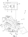
- a compact utility machine is shown in the form of compact loader 10 that is equipped with a passive cooling system 12.
- the compact loader 10 may be one of the general type that is commercially available from Wacker Neuson America Corporation of Menomonee Falls, Wisconsin.
- compact loader 10 includes a chassis 16 with a frame 18 that provides an undercarriage and a boom support to a boom 20 with lift arms 22.
- Lift arms 22 are attached at their upper ends 24 to the frame 18 toward a back end of the compact loader 10.
- Tool carrier 28 typically includes a quick-release connector for attaching different tools or accessories to the lift arms 20.
- Operator platform 30, shown configured to accommodate a standing operator, is connected to the frame 18 at an operator end or the back end of compact loader 10.
- drive system 40 includes an engine 42, represented here as an air-cooled engine that powers hydraulic system 44.
- Hydraulic system 44 provides hydraulic power for moving the compact loader 10 by selectively driving a pair of drive motors 46 (only one shown) to independently control rotation of tracks 48 (only one shown).
- Hydraulic system 44 is also used for actuating the boom 20 and its carried tool or accessory through lift/lower and curl/uncurl functions. Hydraulic system 44 further provides auxiliary hydraulic flow to power hydraulically powered accessories through hydraulic remotes 49.
- passive cooling system 12 typically includes at least portions of various bodywork-type components of compact loader 10.
- the bodywork may provide an engine compartment 50 that is implemented as an enclosure with interconnected panels. These panels may include a belly pan or bottom wall 52 that is defined by a portion of or otherwise supported by frame 18 and rear compartment baffle 54 that is connected to bottom wall 52 and that extends angularly up and rearwardly, supporting a portion of the hydraulic system 44 at its rearward end, toward the operator platform 30.
- Engine support platform 56 is supported by frame 18, to which engine 42 is mounted, and is vertically spaced above bottom wall 52.
- the panels also include a hood or top wall 58 that defines an upper boundary of the engine compartment 50 and side walls 60, 62 (only sidewall 60 shown in this view) that define side boundaries of the engine compartment 50.
- Engine compartment 50 includes a main compartment segment 70 and nose segment 72.
- a fan shroud 74 separates the main compartment segment 70 and nose segment 72.
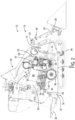
- passive cooling system 12 is configured to evacuate air from the engine compartment 50 and to draw in ambient air. This establishes a cooling airflow through the engine compartment 50 from its back end toward its front end for cooling engine 42 and various components of hydraulic system 44.
- Hydraulic system 44 has at least one hydraulic pump, shown here as a pump stack 80 with multiple axially aligned and connected pumps 82, 84, 86. With respect to a back-to-front airflow through ending compartment 50, the pump stack 80 is mounted upstream relative to engine 42.
- the pump stack 80 By being upstream of the engine 42 relative to a flow direction of a cooling-airflow, the pump stack 80 is in an operational envelope that is substantially outside of a heat-influence zone of the engine 42, since heated air from the engine is substantially evacuated in a forward direction. Also upstream of engine 42 is the hydraulic system's hydraulic oil cooler 88. The oil cooler's 88 operational envelope is also substantially outside of the heat-influenced zone of the engine 42.
- coupler 90 connects an input shaft 92 the pump stack 80 to an output shaft 94 of engine 42, spacing the pump stack from the engine 42.
- coupler 90 is a jaw-style coupler with rubber or other damping elements 96 between cooperating teeth of segments of coupler 90 that are respectively mounted to the pump stack input shaft 92 and engine output shaft 94.
- Engine output shaft 94 is axially aligned with or corresponds to the engine's crankshaft 100.
- Crankshaft 100 drives a PTO shaft or defines a PTO output at a first or forward end 102.
- An exhaust fan 104 with blades 106 is mounted to PTO shaft or forward crankshaft end 102, within an opening of fan shroud 74.
- the engine's flywheel 110 is mounted to the crankshaft 100.
- a blower housing 112 is mounted to the engine 42 and generally encloses an engine-cooling fan 114 with blades 116. Blower housing 112 radially shrouds the engine-cooling fan 114 and is configured to direct a corresponding airflow across and around engine 42.
- the exhaust fan 104 and engine-cooling fan 114 are coaxially aligned and rotate in unison with each other, driven at opposite ends of crankshaft 100.
- Engine-cooling fan 114 may be radially smaller than and have a lower flow rate than that of exhaust fan 104. It is understood that the exhaust fan 104 may provide a greater flow rate than the engine-cooling fan 114 and yet have the same or a smaller radius than the engine-cooling fan 114, based on factors such as blade pitch or surface area.
- both the exhaust fan 104 and engine-cooling fan 114 rotate, which evacuates air out of the front of the engine compartment 50.
- the exhaust and engine cooling fans 104, 114 push air out of engine compartment's 50 main compartment segment 70 into a nose segment 72, which is vented to the atmosphere.
- This establishes a pressure differential across the fan shroud 74, with a negative pressure zone 120 with a lower than ambient pressure defined in the main compartment segment 70, represented by horizontal dashed-lines, and a positive pressure zone 122 with a higher than ambient pressure defined in the nose segment 72, represented by horizontal solid-lines.
- the pressure differential(s) between the negative pressure zone 120 and positive pressure zone 122 establish various airflows through the engine compartment 50 that allow the passive cooling system 12 to cool various components, such as those of hydraulic system 44.
- the airflows and airflow segments and flow directions and characteristics are established as functions of the configurations and locations of various inlets and outlets as well as a passive air flow driving force established by a pressure differential(s) provided between the engine compartment 50 and the ambient.
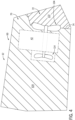
- Each of the engine compartment's side walls 60, 62 is shown with a respective inlet 130, 132.
- Each of interconnected walls 140, 142, 144 of the engine enclosure's nose segment 72 is shown with respective outlets 150, 152, 154.
- the outlets 150, 152, 154 of the nose segment's walls 140, 142, 144 occupy the major wall surface areas of the nose segment's walls 140, 142, 144.
- the nose segment's walls 140, 142, 144 have a substantially open mesh or screen configuration with typically at least 50% openness of surface area, and more typically at least 80% openness, to permit free airflow therethrough.
- the exhaust and engine-cooling fans 104, 114 rotate to force air out of the main compartment segment 70 and into the nose segment 72, pressurizing the nose segment 72 and drawing a vacuum within the main compartment segment 70.
- the negative pressure zone 120 and positive pressure zone 122 are established.
- the vacuum in the negative pressure zone 120 draws ambient air as cooling air into the main compartment segment 70.
- a first inlet airflow segment or volume 160 is drawn through inlet 130.
- the first inlet airflow segment 160 is directed through the oil cooler 88, which is typically mounted to side wall 60 at a position that overlies inlet 130.
- a second inlet airflow segment 162 or volume is drawn through inlet 132 into the general open space in the main compartment segment 70.
- the first and second inlet airflow segments 160, 162 initially flow toward each other, perpendicularly with respect to a centerline of the engine compartment 50.
- the first and second inlet airflow segments 160, 162 merge with each other and change direction to flow parallel to the centerline of the engine compartment 50, defining a merged airflow segment 164 or volume that is represented by the longer bold and solid arrows.
- the merged airflow segment 164 flows toward the exhaust and engine-cooling fans 104, 114. At least some of the merged airflow segment 164 is drawn into an annular inlet of blower housing 112.
- engine-cooling fan 114 pushes a volume of air as an engine-cooling airflow segment or vloume166, represented as thin open arrows, across the engine 42 and toward exhaust fan 104.
- the exhaust fan 104 pushes a volume of air through the opening of fan shroud 74, into the nose segment 72 as an exhaust airflow segment or volume 168, represented by thick open arrows.
- the exhaust airflow segment 168 diffuses out of the outlets 150, 152, 154 as driven out by the pressurization of positive pressure zone 122.
- the passive cooling system 12 may implement forward-mounted air-moving components driven by and/or incorporated into an air-cooled engine 42 to direct the heated air out the front of the compact loader 10. This passively provides substantial cooling of the hydraulic system 44 while directing the heated air away from the operator. Since the airflow(s) of passive cooling system 12 directs the exhausted air away the operator, not only is the operator exposed to less component operational heat during use, but the operator is also exposed to less dust or other air-entrained particles that are common during machine operation.
Landscapes
- Engineering & Computer Science (AREA)
- General Engineering & Computer Science (AREA)
- Mining & Mineral Resources (AREA)
- Civil Engineering (AREA)
- Structural Engineering (AREA)
- Mechanical Engineering (AREA)
- Chemical & Material Sciences (AREA)
- Combustion & Propulsion (AREA)
- Component Parts Of Construction Machinery (AREA)
- Cooling, Air Intake And Gas Exhaust, And Fuel Tank Arrangements In Propulsion Units (AREA)
Applications Claiming Priority (1)
| Application Number | Priority Date | Filing Date | Title |
|---|---|---|---|
| US18/099,023 US20240247465A1 (en) | 2023-01-19 | 2023-01-19 | Compact Utility Machine with a Passive Cooling System |
Publications (2)
| Publication Number | Publication Date |
|---|---|
| EP4414539A2 true EP4414539A2 (fr) | 2024-08-14 |
| EP4414539A3 EP4414539A3 (fr) | 2024-12-11 |
Family
ID=89619403
Family Applications (1)
| Application Number | Title | Priority Date | Filing Date |
|---|---|---|---|
| EP24151933.9A Pending EP4414539A3 (fr) | 2023-01-19 | 2024-01-15 | Machine utilitaire compacte avec système de refroidissement passif |
Country Status (2)
| Country | Link |
|---|---|
| US (1) | US20240247465A1 (fr) |
| EP (1) | EP4414539A3 (fr) |
Family Cites Families (9)
| Publication number | Priority date | Publication date | Assignee | Title |
|---|---|---|---|---|
| GB731326A (en) * | 1952-07-05 | 1955-06-08 | Porsche Ferdinand A | An improved arrangement of oil cooler in air cooled internal combustion engines |
| DE2934095A1 (de) * | 1979-08-23 | 1981-03-26 | Klöckner-Humboldt-Deutz AG, 51063 Köln | Verkleidung fuer eine insbesondere in einem kraftfahrzeug einbaubare luftgekuehlte brennkraftmaschine |
| DE3423531A1 (de) * | 1984-03-23 | 1985-10-03 | Owatonna Manufacturing Co.,Inc., Owatonna, Minn. | Aufschwenkbare anordnung aus motor- und oelkuehler |
| US7492050B2 (en) * | 2006-10-24 | 2009-02-17 | Briggs & Stratton Corporation | Cooling system for a portable generator |
| KR101001869B1 (ko) * | 2008-03-31 | 2010-12-17 | 국제종합기계 주식회사 | 엔진 냉각장치를 포함하는 이앙기 |
| JP5594197B2 (ja) * | 2011-03-16 | 2014-09-24 | コベルコ建機株式会社 | 建設機械の冷却構造 |
| JP5949730B2 (ja) * | 2013-11-07 | 2016-07-13 | コベルコ建機株式会社 | 建設機械の電装品配設構造 |
| JP6591356B2 (ja) * | 2016-06-21 | 2019-10-16 | 株式会社クボタ | 作業機 |
| CA3148815A1 (fr) * | 2019-07-29 | 2021-02-04 | Great Plains Manufacturing, Inc. | Chargeur utilitaire compact |
-
2023
- 2023-01-19 US US18/099,023 patent/US20240247465A1/en active Pending
-
2024
- 2024-01-15 EP EP24151933.9A patent/EP4414539A3/fr active Pending
Also Published As
| Publication number | Publication date |
|---|---|
| US20240247465A1 (en) | 2024-07-25 |
| EP4414539A3 (fr) | 2024-12-11 |
Similar Documents
| Publication | Publication Date | Title |
|---|---|---|
| US6302066B1 (en) | Apparatus and method of cooling a work machine | |
| US8104559B2 (en) | Multiple air flow paths using single axial fan | |
| US4815550A (en) | Engine cooling system for skid steer loaders | |
| CN102105639B (zh) | 用于机械的冷却系统封装布置 | |
| CA1073007A (fr) | Tracteur a moteur avant ayant un echangeur thermique transversal median | |
| US8403089B2 (en) | Use of fan shroud to ventilate engine compartment | |
| US3727712A (en) | Cooling arrangement | |
| EP1338705A1 (fr) | Machines de chantier | |
| US3868992A (en) | Gross flow cooling system | |
| EP4414539A2 (fr) | Machine utilitaire compacte avec système de refroidissement passif | |
| JP2025079595A (ja) | 電動作業車 | |
| US7028646B1 (en) | Cooling system for skid steer loader including fan assembly mounted to engine | |
| JP4056405B2 (ja) | 草刈機の冷却構造 | |
| JP7423560B2 (ja) | 作業車両の冷却装置および作業車両 | |
| US12371876B2 (en) | Work machine | |
| JP3511283B2 (ja) | 建設機械の冷却装置 | |
| JPH11280112A (ja) | 建設機械の冷却装置 | |
| JP3046271B2 (ja) | 走行作業機におけるエンジン等の配置機構 | |
| EP4726110A1 (fr) | Machine de travail | |
| JP3051691B2 (ja) | 走行作業機におけるエンジン等の配置機構 | |
| JP2025154226A (ja) | 作業用車両 | |
| JPH11241369A (ja) | 建設機械の冷却装置 | |
| JP3073332B2 (ja) | 旋回型作業車 | |
| JPH11269920A (ja) | 建設機械の冷却装置 | |
| JP2012126337A (ja) | 走行車両 |
Legal Events
| Date | Code | Title | Description |
|---|---|---|---|
| PUAI | Public reference made under article 153(3) epc to a published international application that has entered the european phase |
Free format text: ORIGINAL CODE: 0009012 |
|
| STAA | Information on the status of an ep patent application or granted ep patent |
Free format text: STATUS: THE APPLICATION HAS BEEN PUBLISHED |
|
| AK | Designated contracting states |
Kind code of ref document: A2 Designated state(s): AL AT BE BG CH CY CZ DE DK EE ES FI FR GB GR HR HU IE IS IT LI LT LU LV MC ME MK MT NL NO PL PT RO RS SE SI SK SM TR |
|
| PUAL | Search report despatched |
Free format text: ORIGINAL CODE: 0009013 |
|
| AK | Designated contracting states |
Kind code of ref document: A3 Designated state(s): AL AT BE BG CH CY CZ DE DK EE ES FI FR GB GR HR HU IE IS IT LI LT LU LV MC ME MK MT NL NO PL PT RO RS SE SI SK SM TR |
|
| RIC1 | Information provided on ipc code assigned before grant |
Ipc: F01P 5/02 20060101ALN20241104BHEP Ipc: F01P 1/00 20060101ALN20241104BHEP Ipc: E02F 9/08 20060101ALI20241104BHEP Ipc: E02F 3/34 20060101ALI20241104BHEP Ipc: F01P 5/06 20060101ALI20241104BHEP Ipc: F01P 1/06 20060101ALI20241104BHEP Ipc: F01P 1/02 20060101AFI20241104BHEP |
|
| STAA | Information on the status of an ep patent application or granted ep patent |
Free format text: STATUS: REQUEST FOR EXAMINATION WAS MADE |
|
| 17P | Request for examination filed |
Effective date: 20250611 |
|
| GRAP | Despatch of communication of intention to grant a patent |
Free format text: ORIGINAL CODE: EPIDOSNIGR1 |
|
| STAA | Information on the status of an ep patent application or granted ep patent |
Free format text: STATUS: GRANT OF PATENT IS INTENDED |
|
| RIC1 | Information provided on ipc code assigned before grant |
Ipc: F01P 1/02 20060101AFI20251118BHEP Ipc: F01P 1/06 20060101ALI20251118BHEP Ipc: F01P 5/06 20060101ALI20251118BHEP Ipc: E02F 3/34 20060101ALI20251118BHEP Ipc: E02F 9/08 20060101ALI20251118BHEP Ipc: F01P 1/00 20060101ALN20251118BHEP Ipc: F01P 5/02 20060101ALN20251118BHEP |
|
| INTG | Intention to grant announced |
Effective date: 20251203 |
|
| GRAS | Grant fee paid |
Free format text: ORIGINAL CODE: EPIDOSNIGR3 |
|
| GRAJ | Information related to disapproval of communication of intention to grant by the applicant or resumption of examination proceedings by the epo deleted |
Free format text: ORIGINAL CODE: EPIDOSDIGR1 |
|
| GRAL | Information related to payment of fee for publishing/printing deleted |
Free format text: ORIGINAL CODE: EPIDOSDIGR3 |
|
| STAA | Information on the status of an ep patent application or granted ep patent |
Free format text: STATUS: REQUEST FOR EXAMINATION WAS MADE |
|
| GRAP | Despatch of communication of intention to grant a patent |
Free format text: ORIGINAL CODE: EPIDOSNIGR1 |
|
| STAA | Information on the status of an ep patent application or granted ep patent |
Free format text: STATUS: GRANT OF PATENT IS INTENDED |