EP4414543A2 - Wärmetransportbuspumpen für düsentriebwerk - Google Patents
Wärmetransportbuspumpen für düsentriebwerk Download PDFInfo
- Publication number
- EP4414543A2 EP4414543A2 EP24155886.5A EP24155886A EP4414543A2 EP 4414543 A2 EP4414543 A2 EP 4414543A2 EP 24155886 A EP24155886 A EP 24155886A EP 4414543 A2 EP4414543 A2 EP 4414543A2
- Authority
- EP
- European Patent Office
- Prior art keywords
- pump
- fuel
- engine
- pounds
- gas turbine
- Prior art date
- Legal status (The legal status is an assumption and is not a legal conclusion. Google has not performed a legal analysis and makes no representation as to the accuracy of the status listed.)
- Withdrawn
Links
Images




Classifications
-
- F—MECHANICAL ENGINEERING; LIGHTING; HEATING; WEAPONS; BLASTING
- F02—COMBUSTION ENGINES; HOT-GAS OR COMBUSTION-PRODUCT ENGINE PLANTS
- F02C—GAS-TURBINE PLANTS; AIR INTAKES FOR JET-PROPULSION PLANTS; CONTROLLING FUEL SUPPLY IN AIR-BREATHING JET-PROPULSION PLANTS
- F02C7/00—Features, components parts, details or accessories, not provided for in, or of interest apart form groups F02C1/00 - F02C6/00; Air intakes for jet-propulsion plants
- F02C7/12—Cooling of plants
- F02C7/14—Cooling of plants of fluids in the plant, e.g. lubricant or fuel
- F02C7/141—Cooling of plants of fluids in the plant, e.g. lubricant or fuel of working fluid
-
- F—MECHANICAL ENGINEERING; LIGHTING; HEATING; WEAPONS; BLASTING
- F02—COMBUSTION ENGINES; HOT-GAS OR COMBUSTION-PRODUCT ENGINE PLANTS
- F02C—GAS-TURBINE PLANTS; AIR INTAKES FOR JET-PROPULSION PLANTS; CONTROLLING FUEL SUPPLY IN AIR-BREATHING JET-PROPULSION PLANTS
- F02C7/00—Features, components parts, details or accessories, not provided for in, or of interest apart form groups F02C1/00 - F02C6/00; Air intakes for jet-propulsion plants
- F02C7/22—Fuel supply systems
-
- F—MECHANICAL ENGINEERING; LIGHTING; HEATING; WEAPONS; BLASTING
- F02—COMBUSTION ENGINES; HOT-GAS OR COMBUSTION-PRODUCT ENGINE PLANTS
- F02C—GAS-TURBINE PLANTS; AIR INTAKES FOR JET-PROPULSION PLANTS; CONTROLLING FUEL SUPPLY IN AIR-BREATHING JET-PROPULSION PLANTS
- F02C3/00—Gas-turbine plants characterised by the use of combustion products as the working fluid
- F02C3/20—Gas-turbine plants characterised by the use of combustion products as the working fluid using a special fuel, oxidant, or dilution fluid to generate the combustion products
- F02C3/22—Gas-turbine plants characterised by the use of combustion products as the working fluid using a special fuel, oxidant, or dilution fluid to generate the combustion products the fuel or oxidant being gaseous at standard temperature and pressure
-
- F—MECHANICAL ENGINEERING; LIGHTING; HEATING; WEAPONS; BLASTING
- F02—COMBUSTION ENGINES; HOT-GAS OR COMBUSTION-PRODUCT ENGINE PLANTS
- F02C—GAS-TURBINE PLANTS; AIR INTAKES FOR JET-PROPULSION PLANTS; CONTROLLING FUEL SUPPLY IN AIR-BREATHING JET-PROPULSION PLANTS
- F02C7/00—Features, components parts, details or accessories, not provided for in, or of interest apart form groups F02C1/00 - F02C6/00; Air intakes for jet-propulsion plants
- F02C7/12—Cooling of plants
- F02C7/16—Cooling of plants characterised by cooling medium
-
- F—MECHANICAL ENGINEERING; LIGHTING; HEATING; WEAPONS; BLASTING
- F02—COMBUSTION ENGINES; HOT-GAS OR COMBUSTION-PRODUCT ENGINE PLANTS
- F02C—GAS-TURBINE PLANTS; AIR INTAKES FOR JET-PROPULSION PLANTS; CONTROLLING FUEL SUPPLY IN AIR-BREATHING JET-PROPULSION PLANTS
- F02C7/00—Features, components parts, details or accessories, not provided for in, or of interest apart form groups F02C1/00 - F02C6/00; Air intakes for jet-propulsion plants
- F02C7/12—Cooling of plants
- F02C7/16—Cooling of plants characterised by cooling medium
- F02C7/18—Cooling of plants characterised by cooling medium the medium being gaseous, e.g. air
- F02C7/185—Cooling means for reducing the temperature of the cooling air or gas
-
- F—MECHANICAL ENGINEERING; LIGHTING; HEATING; WEAPONS; BLASTING
- F02—COMBUSTION ENGINES; HOT-GAS OR COMBUSTION-PRODUCT ENGINE PLANTS
- F02C—GAS-TURBINE PLANTS; AIR INTAKES FOR JET-PROPULSION PLANTS; CONTROLLING FUEL SUPPLY IN AIR-BREATHING JET-PROPULSION PLANTS
- F02C7/00—Features, components parts, details or accessories, not provided for in, or of interest apart form groups F02C1/00 - F02C6/00; Air intakes for jet-propulsion plants
- F02C7/22—Fuel supply systems
- F02C7/224—Heating fuel before feeding to the burner
-
- F—MECHANICAL ENGINEERING; LIGHTING; HEATING; WEAPONS; BLASTING
- F05—INDEXING SCHEMES RELATING TO ENGINES OR PUMPS IN VARIOUS SUBCLASSES OF CLASSES F01-F04
- F05D—INDEXING SCHEME FOR ASPECTS RELATING TO NON-POSITIVE-DISPLACEMENT MACHINES OR ENGINES, GAS-TURBINES OR JET-PROPULSION PLANTS
- F05D2220/00—Application
- F05D2220/30—Application in turbines
- F05D2220/32—Application in turbines in gas turbines
- F05D2220/323—Application in turbines in gas turbines for aircraft propulsion, e.g. jet engines
-
- F—MECHANICAL ENGINEERING; LIGHTING; HEATING; WEAPONS; BLASTING
- F05—INDEXING SCHEMES RELATING TO ENGINES OR PUMPS IN VARIOUS SUBCLASSES OF CLASSES F01-F04
- F05D—INDEXING SCHEME FOR ASPECTS RELATING TO NON-POSITIVE-DISPLACEMENT MACHINES OR ENGINES, GAS-TURBINES OR JET-PROPULSION PLANTS
- F05D2260/00—Function
- F05D2260/20—Heat transfer, e.g. cooling
-
- F—MECHANICAL ENGINEERING; LIGHTING; HEATING; WEAPONS; BLASTING
- F05—INDEXING SCHEMES RELATING TO ENGINES OR PUMPS IN VARIOUS SUBCLASSES OF CLASSES F01-F04
- F05D—INDEXING SCHEME FOR ASPECTS RELATING TO NON-POSITIVE-DISPLACEMENT MACHINES OR ENGINES, GAS-TURBINES OR JET-PROPULSION PLANTS
- F05D2260/00—Function
- F05D2260/20—Heat transfer, e.g. cooling
- F05D2260/213—Heat transfer, e.g. cooling by the provision of a heat exchanger within the cooling circuit
-
- F—MECHANICAL ENGINEERING; LIGHTING; HEATING; WEAPONS; BLASTING
- F05—INDEXING SCHEMES RELATING TO ENGINES OR PUMPS IN VARIOUS SUBCLASSES OF CLASSES F01-F04
- F05D—INDEXING SCHEME FOR ASPECTS RELATING TO NON-POSITIVE-DISPLACEMENT MACHINES OR ENGINES, GAS-TURBINES OR JET-PROPULSION PLANTS
- F05D2260/00—Function
- F05D2260/81—Modelling or simulation
Definitions
- This disclosure relates generally to fluid pumps, and, more particularly, to pumps for aircraft jet engines.
- Aircraft typically include various accessory systems supporting the operation of the aircraft and/or its gas turbine engine(s).
- such accessory systems may include a lubrication system that lubricates components of the engine(s), an engine cooling system that provides cooling air to engine components, an environmental control system that provides cooled air to the cabin of the aircraft, and/or the like.
- a fluid e.g., oil, air, etc.
- a thermal management system such as a closed-loop advanced Brayton cycle.
- A, B, and/or C refers to any combination or subset of A, B, C such as (1) A alone, (2) B alone, (3) C alone, (4) A with B, (5) A with C, (6) B with C, or (7) A with B and with C.
- the phrase "at least one of A and B" is intended to refer to implementations including any of (1) at least one A, (2) at least one B, or (3) at least one A and at least one B.
- the phrase "at least one of A or B" is intended to refer to implementations including any of (1) at least one A, (2) at least one B, or (3) at least one A and at least one B.
- the phrase "at least one of A and B" is intended to refer to implementations including any of (1) at least one A, (2) at least one B, or (3) at least one A and at least one B.
- the phrase "at least one of A or B" is intended to refer to implementations including any of (1) at least one A, (2) at least one B, or (3) at least one A and at least one B.
- connection references e.g., attached, coupled, connected, and joined
- connection references may include intermediate members between the elements referenced by the connection reference and/or relative movement between those elements unless otherwise indicated. As such, connection references do not necessarily infer that two elements are directly connected and/or in fixed relation to each other.
- any part is in "contact" with another part is defined to mean that there is no intermediate part between the two parts.
- descriptors such as “first,” “second,” “third,” etc. are used herein without imputing or otherwise indicating any meaning of priority, physical order, arrangement in a list, and/or ordering in any way, but are merely used as labels and/or arbitrary names to distinguish elements for ease of understanding the disclosed examples.
- the descriptor "first” may be used to refer to an element in the detailed description, while the same element may be referred to in a claim with a different descriptor such as "second” or “third.” In such instances, it should be understood that such descriptors are used merely for identifying those elements distinctly that might, for example, otherwise share a same name.
- forward and aft refer to relative positions within a gas turbine engine, pump, or vehicle, and refer to the normal operational attitude of the gas turbine engine, pump, or vehicle.
- forward refers to a position closer to an engine inlet and aft refers to a position closer to an engine nozzle or exhaust.
- forward refers to a position closer to a pump inlet and aft refers to a position closer to an end of the pump opposite the inlet.
- upstream and downstream refer to the location along a fluid flow path relative to the direction of fluid flow.
- upstream refers to a location from which the fluid flows
- downstream refers to a location toward which the fluid flows.
- an engine inlet is said to be upstream of an engine outlet, and the engine outlet is said to be downstream of the engine inlet.
- the attached figures are annotated with a set of axes including an axis of rotation (e.g., axial axis) z and a radial axis r.
- the attached figures can be annotated with reference to an axial direction A, a radial direction R, and/or a circumferential direction C of the vehicle associated with the features, forces, and moments.
- the axial direction refers to a direction parallel to the axis of rotation z about which the rotating components of a turbine engine rotate.
- the radial direction refers to a direction that is perpendicular to the axis of rotation and points towards (radially inward) or away from (radially outward) the axis of rotation.
- the circumferential direction at a given point is a direction that is normal to a local radial direction and normal to the axial direction.
- the meridional plane refers to the plane formed by the axis of rotation and the radial axis.
- thrust class refers to a group or classification of gas turbine engines, or a type of gas turbine engine that can generate a similar amount of thrust during various flight conditions (e.g., takeoff, cruise, landing, etc.), as specified in engine certification documents.
- a first thrust class includes one or more gas turbine engines that generate a maximum cruise thrust between 30000 pounds-force (lbf) and 40000 lbf.
- SFC specific fuel consumption
- normalization refers to the creation of shifted and scaled versions of variables used in relationships disclosed herein.
- the normalized valves allow for the comparison of variables, ratios, and/or relationships in a way that eliminates or lessens the effects of certain gross influences (e.g., density, viscosity, specific heat capacity, etc.).
- pump power refers to the power the pump uses to pressurize a working fluid to a mass flow rate.
- corrected pump power refers to the pump power that is normalized based on the properties of water to represent the pump power used to pressurize water to the same mass flow rate.
- rotor diameter refers to an exit diameter of a most upstream rotor in a pump.
- the most upstream rotor can be either the only rotor in a single-stage pump or the most upstream rotor in a multistage pump.
- the most upstream rotor is the impeller that the working fluid first contacts upon flowing into the inlet of the pump.
- corrected rotor diameter refers to an exit diameter of the most upstream rotor in the pump that has been normalized based on the properties of water.
- a first pump includes a first impeller having a rotor diameter to pressurize a working fluid to a certain mass flow rate
- a second pump can include a second impeller with a corrected rotor diameter to pressurize water to the same mass flow rate.
- exit diameter refers to the diameter of a rotor (e.g., an impeller of a centrifugal/radial pump/compressor or a rotor of an axial pump/compressor) at a most downstream point of the rotor.
- the exit diameter corresponds to the diameter at the outermost tip of the impeller vanes.
- the exit diameter corresponds to the diameter at the trailing edge of the rotor blades.
- fuel flow rate refers to the mass flow rate of fuel injected into a combustor of the gas turbine engine to generate thrust for cruising conditions.
- corrected fuel flow rate refers to the fuel flow rate that is normalized based on properties (e.g., specific heat capacities, etc.) of a fuel being burned and a working fluid in a thermal transport bus (described below).
- NHC net heat of combustion
- c p specific heat capacity
- a turbine engine also referred to herein as a gas turbine engine, is a type of internal combustion engine that uses atmospheric air as a moving fluid.
- the gas turbine engine is a turbofan engine that includes a fan section upstream of a low-pressure compressor section and a bypass airflow passage.
- a volume of air enters an inlet of the engine and passes into the fan section.
- a first portion of air is directed or routed into the bypass airflow passage, and a second portion of air is directed or routed into the low-pressure compressor section where the pressure of the air is increased.
- the pressure of the second portion of air is further increased as it is routed through a high-pressure compressor section and into a combustion chamber where the pressurized air is mixed with fuel and burned to provide combustion gases.
- the combustion gases are routed through a high-pressure turbine section and a low-pressure turbine section, where a portion of thermal and/or kinetic energy from the combustion gases is extracted.
- the combustion gases are then routed through a jet exhaust nozzle section of the gas turbine engine to provide propulsive thrust.
- the pressure of the first portion of air is substantially increased as the first portion of air is routed through the bypass airflow passage before it is exhausted from a fan nozzle exhaust section of the turbofan engine, also providing propulsive thrust.
- the combination of propulsive thrusts from the first and second portions of air determines an overall thrust that the turbofan engine generates to propel the aircraft in flight.
- the power of the gas turbine engine can be defined as a product of the overall thrust and the cruising speed of the aircraft. In general, as the size of the gas turbine engine increases, so does the engine power, the thrust class, and the SFC thereof.
- TMSs thermal management systems
- a working fluid e.g., water, oil, supercritical carbon dioxide (sCO2), liquid helium, helium-xenon, etc.
- sCO2 supercritical carbon dioxide
- Such TMSs can heat or cool accessory systems, sections, and/or components in the engine(s) to improve the power, efficiency, and/or structural integrity thereof.
- the TMS includes the thermal transport bus (TTB) to transmit the working fluid (or heat exchange fluid) between elements (e.g., accessory systems, sections, components, etc.) of the gas turbine engine such that heat can be transferred to/from the working fluid and from/to the elements.
- TTB thermal transport bus
- the TMS uses sCO2 as the working fluid because it has a low viscosity and a high specific heat, enabling heat exchangers to efficiently transfer heat to and/or from the sCO2.
- sCO2 is chemically stable, reliable, readily available, and non-flammable, making sCO2 more advantageous than some other heat exchange fluids (e.g., water, air, etc.).
- sCO2 is not prone to phase changes, unlike other heat exchange fluids, such as water, that can freeze or evaporate.
- the TMS includes a TTB pump (or sCO2 pump) to pressurize the sCO2 within the TTB.
- the TTB pump may be a centrifugal pump or an axial pump (e.g., a single-stage centrifugal pump, a multistage centrifugal pump, a multistage axial pump, etc.) that uses an electric motor to rotate a shaft coupled to one or more rotors (e.g., impellers, rotor blades, etc.), which draws the working fluid into a pump inlet and accelerates the working fluid radially and/or axially to the pump outlet and/or other rotors in the pump.
- the TTB is a rotary screw pump, as described below.
- the motor converts electrical energy of an armature into mechanical work of a shaft coupled thereto.
- the shaft generates a torque and rotates at a rotational speed. Because the rotor is coupled to the shaft, the torque is transferred to the rotor, and the rotor rotates at the same angular velocity.
- Pump power e.g., mechanical power, fluid power, etc.
- Pump power corresponds to a product of the amount of torque generated and the rotational speed of the shaft.
- the rotational speed also increases.
- the rotor(s) compress or pressurize the working fluid to a certain pressure head.
- pressure head is used herein as a measure of kinetic energy that the pump generates.
- the pressure head is the measurement of a height of an incompressible fluid column that the pump could create based on the kinematic energy provided to the incompressible fluid.
- the working fluid accelerates, and a mass flow rate of the working fluid (e.g., compressible fluid, such as sCO2) also increases.
- the angular velocity (or rotational speed) of the rotor (e.g., impeller for centrifugal pumps, rotor blades for axial pumps, etc.) remains constant along its diameter.
- a tangential velocity at a point on the rotor equals the product of the angular velocity and a distance from the point to an axis of rotation of the rotor.
- the tangential velocity of the rotor is largest at its tip and/or outer diameter.
- the pressure head that the rotor generates is directly proportional to the tangential velocity at an exit diameter of the rotor. For example, when the pump is a single-stage centrifugal pump with an impeller as the rotor, the pressure head doubles as the impeller diameter doubles.
- the pump head is directly proportional to the square of the angular velocity of the rotor. For example, when the angular velocity doubles, the pressure head quadruples. Therefore, since the mass flow rate increases with the pressure head, and the pressure head increases with the angular and tangential velocities, both the pump power and the rotor diameter affect the mass flow rate that the pump can supply.
- the temperature of the fuel can affect the SFC (or efficiency) of an engine. That is to say, increasing the temperature of the fuel prior to injection into the combustion chamber can increase the energy (heat) generated while reducing the amount of fuel consumed, which can improve (reduce) the SFC of the gas turbine engine.
- the mass flow rate of the working fluid within the TMS can affect the amount of heat transferred to the fuel.
- the pump power and the rotor diameter of the TTB pump affect the mass flow rate, a certain pump power and/or a rotor diameter can be determined to improve the SFC of a gas turbine engine based on a certain thrust class (or corrected fuel flow rate) of the gas turbine engine.
- the TTB pump can be designed to produce a pump power that can improve the SFC of the engine without introducing other unacceptable drawbacks, such as increased engine weight, increased pump volume, reduced engine efficiency, etc.
- Designing the TTB pump to improve the SFC of the engine can be a challenging process that involves many tradeoffs between the TTB pump size and the SFC benefit that the TTB pump provides.
- the pump may be fitted with a larger motor, drive shaft, compressor, etc., which ultimately increases the volume and weight of the pump.
- Analyses are typically performed and iterated upon to design a TTB pump that outputs a proper amount of power for a particular aircraft thrust-producing gas turbine engine without oversizing the TTB pump.
- Such analyses can be uncertain, indeterminate, time-consuming, and are regarded as highly dependent upon a particular engine architecture.
- TTB pumps When designing a TTB pump for a particular thrust class, there is no conventional design standard that limits the size of the pump while also providing a pump power to achieve the desired SFC benefit. As such, conventional TTB pumps can be oversized or undersized for a given thrust class. Increasing the pump power improves the SFC, but also increases the size of the TTB pump. At a certain point, the SFC benefits from increased pump power are outweighed by the increased size (e.g., weight and volume) of the pump. In other words, the TTB pump design can be oversized in an attempt to improve the SFC of the engine. On the other hand, the power of the TTB pump may be reduced in an attempt to limit the weight and volume of the pump.
- the inventors developed architectures for gas turbine engines and the TTB pump of the TMS in the aircraft. Particularly, the inventors proceeded in the manner of designing TTB pumps with given performance characteristics of the pump motor (e.g., power, etc.) and dimensional characteristics of the pump rotor (e.g., exit diameter, etc.). The inventors redesigned the TTB pump to achieve particular mass flow characteristics of the working fluid in the TMS and heat transfer rates between the working fluid and the fuel in the engine, hence increasing the temperature of the fuel, improving an SFC of the gas turbine engine, and reducing overall fuel consumption of the engine.
- the pump motor e.g., power, etc.
- dimensional characteristics of the pump rotor e.g., exit diameter, etc.
- the inventors rechecked the TTB pump power, the exit rotor diameter, the size of the TTB pump, and the SFC of the engine that resulted from the redesigned TTB pump during the design of several different types of gas turbine engines and TTB pumps, including the TTB pumps and engines described below in connection with FIGS. 6 and 7 .
- TTB pump During the process of studying and evaluating various performance characteristics of TTB pump, and size characteristics (e.g., dimensions, weight, etc.) of the TTB pump considered feasible for best satisfying flight requirements, the inventors unexpectedly discovered that a certain relationship exists between pump power and a fuel flow rate of the engine as well as a relationship between pump exit rotor diameter and the fuel flow rate of the engine. These relationships provide a certain sized TTB pump that improves the SFC of the engine while reducing the weight of the TTB pump and providing additional space in the aircraft and/or the engine for other components, systems, and subsystems. This discovery is described in greater detail below.
- FIG. 1 is a side view of an example aircraft 10.
- the aircraft 10 includes a fuselage 12 and a pair of wings 14 (one is shown) extending outward from the fuselage 12.
- a gas turbine engine 100 is supported on each wing 14 to propel the aircraft through the air during flight.
- the aircraft 10 includes a vertical stabilizer 16 and a pair of horizontal stabilizers 18 (one is shown).
- the aircraft 10 includes engines of different types and/or in different positions than the illustrative example of FIG. 1 .
- the aircraft 10 includes a thermal management system 102 (TMS 102) for transferring heat between fluids supporting the operation of the aircraft 10.
- TMS 102 thermal management system
- the aircraft 10 includes one or more accessory systems configured to support the operation of the aircraft 10.
- accessory systems include a lubrication system that lubricates components of the engines 100, a cooling system that provides cooling air to components of the engines 100, an environmental control system that provides cooled air to the cabin of the aircraft 10, and/or the like.
- the TMS 102 is configured to transfer heat from one or more fluids supporting the operation of the aircraft 10 (e.g., the oil of the lubrication system, the air of the cooling system and/or the environmental control system, and/or the like) to one or more other fluids supporting the operation of the aircraft 10 (e.g., the fuel supplied to the engines 100).
- the TMS 102 is configured to transfer heat directly to and/or from other components that support the operation of the aircraft 10 without an intermediate fluid.
- examples disclosed herein are described with reference to the aircraft 10 of FIG. 1 , examples disclosed herein can be applicable to another type or configuration of aircraft that uses a thermal management system similar to the TMS 102 of FIGS. 1-3 .
- the present subject matter can be readily adaptable to another aircraft (e.g., military jet aircraft, cargo aircraft, etc.) with another engine (e.g., turbojet, turboprop, etc.).
- the TMS 102 of FIG. 1 is shown as located in the fuselage 12 of the aircraft 10, the TMS 102 (or a portion of the TMS 102, such as the TTB, a heat exchanger, the TTB pump, etc.) can be located within the wing 14, the engine 100, and/or another location in the aircraft 10.
- FIG. 2 is a schematic cross-sectional view of an example gas turbine engine 100.
- the engine 100 is configured as a high-bypass turbofan engine.
- the engine 100 is configured as a propfan engine, a turbojet engine, a turboprop engine, a turboshaft gas turbine engine, and/or the like.
- the engine 100 includes the TMS 102. In some examples, the entire TMS 102 is located within the engine 100. In some examples, a portion of the TMS 102 is located in the engine 100 and other portion(s) of the TMS 102 are located in other component(s) (e.g., the fuselage 12, the wing 14, etc.) of the aircraft 10.
- the engine 100 extends along an axial centerline 103 and includes a fan 104, a low-pressure (LP) spool 106, and a high pressure (HP) spool 108, which are at least partially encased by an annular housing or nacelle 110.
- LP low-pressure
- HP high pressure
- the fan 104 can include a fan rotor 112 and a plurality of fan blades 114 (one is shown) coupled to the fan rotor 112.
- the fan blades 114 are circumferentially spaced apart and extend radially outward from the fan rotor 112.
- the LP and HP spools 106, 108 are positioned downstream from the fan 104 along the axial centerline 103.
- the LP spool 106 is rotatably coupled to the fan rotor 112, which permits the LP spool 106 to rotate the fan blades 114.
- a plurality of outlet guide vanes or struts 116 are circumferentially spaced apart from each other and extend radially between an outer casing 118 surrounding the LP and HP spools 106, 108 and the nacelle 110.
- the struts 116 support the nacelle 110 relative to the outer casing 118 such that the outer casing 118 and the nacelle 110 define a bypass airflow passage 120 positioned therebetween.
- the outer casing 118 generally surrounds or encases, in serial flow order, a compressor section 122, a combustion section 124, a turbine section 126, and an exhaust section 128.
- the compressor section 122 includes a low-pressure (LP) compressor 130 of the LP spool 106 and a high-pressure (HP) compressor 132 of the HP spool 108 positioned downstream from the LP compressor 130 along the axial centerline 103.
- Each compressor 130, 132 can, in turn, include one or more rows of compressor stator vanes 134 interdigitated with one or more rows of compressor rotor blades 136. As such, the compressors 130, 132 define a compressed air flow path 133 extending therethrough.
- the turbine section 126 includes a high-pressure (HP) turbine 138 of the HP spool 108 and a low-pressure (LP) turbine 140 of the LP spool 106 positioned downstream from the HP turbine 138 along the axial centerline 103.
- HP high-pressure
- LP low-pressure
- Each turbine 138, 140 can, in turn, include one or more rows of turbine stator vanes 142 interdigitated with one or more rows of turbine rotor blades 144.
- the LP spool 106 includes a low-pressure (LP) shaft 146 and the HP spool 108 includes a high-pressure (HP) shaft 148 positioned concentrically around the LP shaft 146.
- the HP shaft 148 rotatably couples the turbine rotor blades 144 of the HP turbine 138 and the compressor rotor blades 136 of the HP compressor 132 such that rotation of the turbine rotor blades 144 of the HP turbine 138 rotatably drives the compressor rotor blades 136 of the HP compressor 132.
- the LP shaft 146 is directly coupled to the turbine rotor blades 144 of the LP turbine 140 and the compressor rotor blades 136 of the LP compressor 130.
- the LP shaft 146 is coupled to the fan 104 via a gearbox 150.
- the rotation of the turbine rotor blades 144 of the LP turbine 140 rotatably drives the compressor rotor blades 136 of the LP compressor 130 and the fan blades 114.
- the engine 100 generates thrust to propel an aircraft. More specifically, during operation, air 152 enters an inlet portion 154 of the engine 100.
- the fan 104 supplies a first portion 156 of the air 152 to the bypass airflow passage 120 and a second portion 158 of the air 152 to the compressor section 122.
- the second portion 158 of the air 152 first flows through the LP compressor 130 in which the compressor rotor blades 136 therein progressively compress the second portion 158 of the air 152.
- the second portion 158 of the air 152 flows through the HP compressor 132 in which the compressor rotor blades 136 therein continue to progressively compress the second portion 158 of the air 152.
- the compressed second portion 158 of the air 152 is subsequently delivered to the combustion section 124.
- the combustion section 124 the second portion 158 of the air 152 mixes with fuel and burns to generate high-temperature and high-pressure combustion gases 160.
- the combustion gases 160 flow through the HP turbine 138 in which the turbine rotor blades 144 of the HP turbine 138 extract a first portion of kinetic and/or thermal energy therefrom.
- This energy extraction rotates the HP shaft 148, which drives the HP compressor 132.
- the combustion gases 160 then flow through the LP turbine 140 in which the turbine rotor blades 144 of the LP turbine 140 extract a second portion of kinetic and/or thermal energy therefrom.
- This energy extraction rotates the LP shaft 146, which drives the LP compressor 130 and the fan 104 via the gearbox 150.
- the combustion gases 160 then exit the engine 100 through the exhaust section 128.
- the aircraft 10 includes the TMS 102 for transferring heat between fluids supporting the operation of the aircraft 10.
- the TMS 102 is positioned within the engine 100.
- the TMS 102 is positioned within the outer casing 118 of the engine 100.
- the TMS 102 (or portions of the TMS 102) is positioned at another location within the engine 100, such as the nacelle 110.
- the TMS 102 transfers heat to a fuel flowing through a fuel supply flowline 170.
- the fuel supply flowline 170 transmits fuel from a supply tank and/or a fuel pump to the combustion section 124.
- the TMS 102 transfers heat from a working fluid (e.g., a heat exchange fluid such as a supercritical fluid (e.g., supercritical carbon dioxide (sCO 2 ), etc.)) within the TTB to the fuel within the fuel supply flowline 170 via a heat sink exchanger (described below).
- a working fluid e.g., a heat exchange fluid such as a supercritical fluid (e.g., supercritical carbon dioxide (sCO 2 ), etc.
- the pump power and/or the rotor diameter of the TTB pump of the TMS 102 affect the rate of heat transfer between the working fluid and the fuel. Additionally, the heat of the fuel in the fuel supply flowline 170 (upstream of the combustion section 124) can affect the SFC of the engine. Thus, it is advantageous for the TMS 102 to produce a certain pressure and/or flow rate with an efficiently sized TTB pump such that the SFC of the engine is effectively improved without the TMS 102 adding substantial weight to the engine 100.
- examples disclosed herein are described with reference to the gas turbine engine 100 of FIG. 2 , examples disclosed herein can be applicable to another type or configuration of engine that uses a thermal management system similar to the TMS 102 of FIGS. 1-3 .
- the present subject matter can be readily adaptable to another engine and/or another heat transfer application associated with another type of aircraft.
- FIG. 3 is a schematic diagram of an example implementation of the TMS 102 for transferring heat between fluids.
- the TMS 102 is discussed in the context of the aircraft 10 and the gas turbine engine 100 described above and shown in FIGS. 1 and 2 .
- the TMS 102 can be implemented within another type of aircraft and/or another gas turbine engine of another configuration.
- the TMS 102 includes a thermal transport bus 302 to transmit a working fluid (e.g., a heat exchange fluid) throughout the TMS 102.
- the thermal transport bus 302 (TTB 302) includes one or more fluid conduits through which the working fluid flows.
- the working fluid flows through various heat exchangers such that heat is added to and/or removed from the working fluid.
- the working fluid can be supercritical carbon dioxide (sCO2), oil, liquid helium, helium-xenon, and/or the like.
- the TMS 102 includes a thermal transport bus pump 304 (TTB pump 304) to pump the working fluid through the TTB 302.
- the TTB pump 304 of the TMS 102 includes a compressor 304a and a power source 304b coupled to a shaft 304c.
- the compressor 304a is rotatably interlocked with the shaft 304c, and the power source 304b drives rotation of the shaft 304c.
- the power source 304b drives rotation of the compressor 304a
- the rotation of the compressor 304a provides a pressure head to the working fluid in the TTB 302 downstream of the TTB pump 304.
- the compressor 304a increases the pressure of the working fluid, the flow rate of the working fluid accelerates downstream toward a low pressure end (e.g., upstream of the TTB pump 304).
- the TTB pump 304 drives the working fluid through the TMS 102.
- the compressor 304a is a centrifugal compressor (or radial compressor) and includes one or more impellers.
- the working fluid can enter along an axis of rotation of the compressor 304a and accelerate radially outward from the rotating impeller into an outlet port, which creates the increased pressure head.
- the compressor 304a is a single-stage centrifugal compressor having a single impeller mounted on an end of the shaft 304c.
- the compressor 304a is a multistage centrifugal compressor having multiple impellers mounted in series along on the shaft 304c.
- the compressor 304a is an axial compressor having multiple stages of rotors and stators that sequentially increase the pressure of the working fluid.
- the working fluid can enter along the axis of rotation of the compressor 304a and pressurize/accelerate along a flow path parallel to the axis of rotation.
- the compressor 304a is a rotary screw compressor including two adjacent shafts with spiral threads that mesh together. As the working fluid radially enters the rotary screw compressor, the two shafts rotate and force the fluid axially along the shafts. The fluid pressure increases as the rotating threads drive the flow into an outlet where the working fluid radially exits from the rotary screw compressor.
- the power source 304b generates torque from electrical and/or mechanical power and transfers that torque along the shaft 304c to the compressor 304a.
- the power source 304b is an electric motor (e.g., direct current (DC) brushless motor, etc.) including fields magnets that emit magnetic fields and an armature (or armature windings) that generate alternating electromagnetic fields.
- the stator or the rotor can be configured as the armature based on the type of example motor implemented as the power source 304b.
- the electric motor includes a rotor and a stator, and the rotor is coupled to the shaft 304c, which rotates based on magnetic interactions between the field magnets and the armature.
- the power source 304b is a turbine that extracts thermal energy of the working fluid in the TTB 302 to generate mechanical power. Such a configuration includes multiple sequential stages of rotating rotor blades and stationary stator blades that generate mechanical power based on the kinetic and thermal energies of the working fluid.
- the TTB pump 304 includes a separate motor coupled to the shaft 304c in conjunction with the power source 304b (e.g., turbine) to supplement the power available to the compressor 304a.
- the power source 304b is configured in another manner to provide power to the compressor 304a that corresponds with a certain pressure output of the TTB pump 304.
- the TMS 102 includes one or more heat source exchangers 306 arranged along the thermal transport bus 302. More specifically, the heat source exchangers 306 are fluidly coupled to the thermal transport bus 302 such that the working fluid flows through the heat source exchangers 306. In some examples, the heat source exchangers 306 transfer heat from fluids supporting the operation of the aircraft 10 to the working fluid, which cools the fluids supporting the operation of the aircraft 10 and heats the working fluid. Although two heat source exchangers 306 are illustrated in FIG. 3 , the TMS 102 of FIGS. 1-3 can include a single heat source exchanger 306 or multiple (e.g., two, three, five, etc.) heat source exchangers 306.
- the heat source exchangers 306 can correspond to heat exchangers for cooling a fluid to support the operation of the aircraft 10.
- at least one of the heat source exchangers 306 is coupled to a lubrication system of the engine 100.
- the heat source exchanger 306 can transfer heat from the oil lubricating the engine 100 to the working fluid.
- at least one of the heat source exchangers 306 is coupled to a cooling system of the engine 100.
- the heat source exchanger 306 can transfer heat from the cooling air bled from the compressor section 122 (or a compressor discharge plenum) of the engine 100 to the working fluid.
- the heat source exchangers 306 correspond to another manner of cooling a fluid supporting the operation of the aircraft 10.
- the TMS 102 includes a plurality of heat sink exchangers 308 arranged along the thermal transport bus 302. More specifically, the heat sink exchangers 308 are fluidly coupled to the thermal transport bus 302 such that the working fluid flows through the heat sink exchangers 308. In some examples, the heat sink exchangers 308 transfer heat from the working fluid to other fluids supporting the operation of the aircraft 10, which heats the other fluids supporting the operation of the aircraft 10 and cools the working fluid. Although two heat sink exchangers 308 are illustrated in FIG. 3 , the TMS 102 of FIGS. 1-3 can include a single heat sink exchanger 308 or multiple (e.g., two, three, five, etc.) heat sink exchangers 308.
- the heat sink exchangers 308 can correspond to heat exchangers for heating a fluid to support the operation of the aircraft 10.
- at least of one of the heat sink exchangers 308 is coupled to a fuel system of the engine 100.
- the heat sink exchanger 308 can transfer heat from the working fluid to the fuel flowing though the fuel supply flowline 170 of the engine 100 of FIG. 2 .
- at least one of the heat sink exchangers 308 contacts the first portion 156 of the air 152 flowing through the bypass airflow passage 120 of the engine 100.
- the heat exchanger 308 can transfer heat from the working fluid to the first portion 156 of the air 152 flowing through the bypass airflow passage 120.
- the TMS 102 of FIG. 3 includes one or more bypass conduits 310 to allow the working fluid to circumvent the heat source exchangers 306 or the heat sink exchangers 308. As shown, each of the bypass conduits 310 is fluidly coupled to the thermal transport bus 302 such that at least a portion of the working fluid can bypass the heat source exchangers 306 or the heat sink exchangers 308. Furthermore, the TMS 102 includes one or more heat source valves 312 to cause a portion of the working fluid to enter the bypass conduits 310 and circumvent one or more of the heat source exchangers 306.
- the TMS 102 also includes one or more heat sink valves 314 to cause a portion of the working fluid to enter the bypass conduits 310 and circumvent one or more of the heat sink heat exchangers 308.
- the heat source valves 312 and the heat sink valves 314 are fluidly coupled to the thermal transport bus 302 and the corresponding bypass conduits 310. Furthermore, the heat source valves 312 and the heat sink valves 314 can be moved between fully and/or partially opened and/or closed positions to selectively occlude the flow of heat exchange through the bypass conduit 310.
- the heat source valve 312 is opened to allow a portion of the working fluid to enter the bypass conduit 310, circumvent the heat source exchanger 306, and reduce the temperature and pressure of the working fluid within the TTB 302 (e.g., to inhibit accelerated wear of the TTB 302).
- the heat sink valve 314 is opened to allow a portion of the working fluid to enter the bypass conduit 310, circumvent the heat sink exchanger 308, and increase the temperature and pressure of the working fluid within the TTB 302 (e.g., to improve the heat transfer capability of the working fluid).
- each heat source exchanger 306 and each heat sink exchanger 308 has a corresponding bypass conduit 310.
- heat source valves 312 and the heat sink valves 314 are hydraulically controlled based on the pressure of the working fluid within the thermal transport bus 302. Thus, for example, when the pressure of the heat exchange fluid satisfies a certain pressure threshold, the heat source valve(s) 312 opens to cause a portion of the working fluid to bypass the heat source exchanger(s) 306.
- TTB pump 304 illustrated in FIG. 3 and the engine 100 of FIGS. 1 and 2 . It will be appreciated that these relationships can be used to design TTB pumps that can be implemented in the TMS 102 of FIGS. 1-3 , the engine 100 of FIGS. 1-2 , or another similar TMS or engine.
- the discovered relationships identify TTB pumps that improve the SFC for certain engine thrust classes without falling outside the scope of benefits to SFC when implementing the relationships set forth below for selecting or designing a pump.
- a TTB pump can be designed to generate a pump power of a desired size based on a thrust class such that the SFC of a gas turbine engine in the thrust class is improved.
- the inventors proceeded to design various TTB pumps that generate differing pump powers and included differing rotor diameters while determining an effectiveness of the TTB pumps to improve the SFC for differing thrust classes, as explained earlier.
- the inventors discovered that a relationship between i) pump power of the TTB pump and ii) fuel flow rate for engines during cruise conditions results in a compact and lightweight TTB pump design (relative to engine size) to produce fuel consumption benefits.
- the inventors discovered unexpectedly that a relationship exists between i) a pump rotor diameter and ii) fuel flow rate to provide a radially compact pump and producing fuel consumption benefits (i.e., lower SFC).
- fuel consumption benefits i.e., lower SFC.
- the inventors discovered that when applying one or both of these relationships to the pump design a lower SFC for an aircraft thrust-producing gas turbine engine can be realized, while avoiding a TTB pump that is larger and/or heavier than needed.
- the unexpected discovery between a pump mass flow rate (mass flow rate of the working fluid exiting the TTB pump) and aircraft fuel mass flow rate (mass flow rate of the fuel injected into the combustion chamber) identifies a pump power and rotor diameter suited for a given engine thrust class.
- the TTB pump designs selected neither oversize nor undersize the pump for a given engine thrust class and provide desired SFC benefits.
- the disclosed relationships also eliminate TTB pump designs that are inefficient, such as TTB pumps that provide too little SFC benefit or TTB pump that are too large for a given engine thrust class.
- the disclosed relationships enable the TTB pump to pressurize the working fluid to a mass flow rate that improves the SFC of an engine while maintaining an efficient size of the TTB pump.
- Some example TTB pump embodiments disclosed below in connections with FIGS. 6 and 7 can increase the pressure of the working fluid to counteract a pressure drop across the TMS.
- some example TTB pump embodiments disclosed herein can improve SFC while accounting for an effectiveness of a heat sink exchanger coupled to the TTB and a fuel supply line, the type of working fluid used in the TTB (e.g., supercritical carbon dioxide (sCO2), liquid helium (He), helium-xenon, etc.), the type of fuel used in the aircraft (e.g., hydrocarbon fuel (Jet-A), hydrogen fuel (H2), etc.), the efficiency of the gas turbine engine, etc.
- the type of working fluid used in the TTB e.g., supercritical carbon dioxide (sCO2), liquid helium (He), helium-xenon, etc.
- the type of fuel used in the aircraft e.g., hydrocarbon fuel (Jet-A), hydrogen fuel (H2), etc.
- the efficiency of the gas turbine engine etc.
- FIG. 4 there is shown in graphical form the aforementioned discovery, which reveals a relationship between the properties of a pressurized working fluid in a thermal transport bus (TTB) and fuel properties for fuel consumed by an aircraft thrust-producing gas turbine engine.
- TTB thermal transport bus
- the fuel-burn benefit to selecting the right size pump for a particular engine size, i.e., lower SFC, could not be realized if the demand for working fluid pressure for heat transfer was not carefully matched to the fuel rate and volume, and temperature environment of a particular engine during operation (cruise conditions).
- a pump for the working fluid that was either oversized (capable of providing more pumping power than needed top transfer heat to the fuel) or undersized (not capable of enabling efficient heat transfer from the working fluid to the fuel) would result in unsatisfactory improvement in SFC for the gas turbine engine during aircraft cruise conditions.
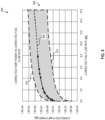
- FIG. 4 shows a first graph 400 that relates a corrected pump power 402 (e.g., Y-axis) and a corrected fuel flow rate 404 (e.g., X-axis).
- the corrected fuel flow rate 404 is representative of engine thrust classes at cruise flight operations.
- the corrected pump power 402 is a pump power output for the TTB pump 304 normalized based on properties (specific heat capacity and density) of water and the chosen working fluid for the TTB 302.
- the corrected fuel flow rate 404 is a rate of fuel consumption for the gas turbine engine 100 of FIGS.
- a first design space 406 (shaded area) of FIG. 4 represents a range of TTB pump designs that were found to efficiently improve the SFC across various engine thrust classes.
- the first design space 406 defines ranges of corrected pump powers that can provide a working fluid (e.g., sCO2, liquid helium, helium-xenon, etc.) at a mass flow rate that effectively heats the fuel for a given corrected fuel flow rate.
- a working fluid e.g., sCO2, liquid helium, helium-xenon, etc.
- the inventors discovered that when the corrected pump power of the TTB pump 304 does not correspond to the first design space 406, the TTP pump 304 is either too small to provide an SFC benefit for the given engine thrust class or is too big to efficiently improve the SFC without being oversized.
- the Y-axis of the first graph 400 represents the corrected pump power 402 of the TTB pump 304 and has dimensional units of horsepower (HP).
- HP horsepower
- the TTB pump 304 generates a pump power, P pump , to pressurize the working fluid to a pressure head in the TTB 302.
- the corrected pump power 402 represents a normalized pump power that the TTB pump 304 can generate to pressurize water to the same pressure head in the TTB 302.
- the pump power, P pump is normalized to the corrected pump power, or POW.
- the corrected pump power, POW is more suitable to define the first design space 406 than the pump power, P pump , based on the view that the POW does not vary as drastically when different working fluids are considered for the TTB pump 304 design and/or when different working fluid properties are used in the pump power, P pump , calculation.
- Fluid properties associated with the working fluid and implemented in the relationships expressed in FIG. 4 and in further respects below include a first specific heat capacity, c p_pump , and a first density, ⁇ pump .
- Fluid properties associated with water and implemented in the disclosed relationships further include a second specific heat capacity, c p_water , and a second density, ⁇ water .
- the X-axis of the first graph 400 in FIG. 4 representing a corrected fuel flow rate 404, has dimensional units of pounds-mass per second (lbm/s).
- the corrected fuel flow rate 404 represents properties of engines across a variety of thrust classes. It was found to account well for differences among engines of differing thrust classes.
- the engine 100 burns fuel at a fuel flow rate to generate an engine power, P engine .
- P engine When a fuel is combusted, the chemical reaction releases energy corresponding to a net heat of combustion, NHC fuel . It was found that a fuel flow rate for the engine 100 can be approximated well by a ratio of the engine power, P engine , to the net heat of combustion of the fuel, NHC fuel .
- This fuel flow rate is normalized to provide a corrected fuel flow rate, FFR, using properties of the fuel in the engine 100 and the working fluid in the TTB 302.
- the inventors discovered that the corrected fuel flow rate, FFR, can more accurately account for variations in engine thrust class than the fuel flow rate because the corrected fuel flow rate FFR, does not vary as drastically when different working fluids are used to transfer heat to the fuel and/or when different fuels are used to power the engine, e.g., engine 100.
- Fluid properties associated with the fuel are referred to as a third specific heat capacity, c p_fuel , and a third density, ⁇ fuel .
- Graph 400 of FIG. 4 identifies a baseline corrected pump power curve 408 (baseline curve 408).
- TTB pumps that generate a corrected pump power POW and fall along the baseline curve 408 can provide an SFC benefit for the given engine thrust class (represented by the associated corrected fuel flowrate, FFR).
- baseline operating curves that produce the desired SFC benefit while avoiding an oversized (or undersized) pump can vary between an upper limit corrected pump power curve 410 (upper curve 410) and a lower limit corrected pump power curve 412 (lower curve 412).
- the first design space 406 is defined as follows: 0.008 ⁇ POW / FFR 5 3 ⁇ 12
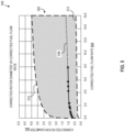
- FIG. 5 shows a second graph 500 that relates a corrected rotor diameter 502 (e.g., Y-axis) and the corrected fuel flow rate 404 (e.g., X-axis).
- the corrected rotor diameter 502 is an exit diameter of a most upstream rotor of the TTB pump 304 of FIG. 3 normalized based on the properties (specific heat capacity) of water and the working fluid in the TTB 302 ( FIG. 3 ).
- the inventors discovered that a second design space 506 of FIG. 5 properly represents a range of TTB pump designs that efficiently improve the SFC of various engine thrust classes.
- the second design space 506 defines ranges of rotor diameters that can provide a working fluid (e.g., sCO2, liquid helium, helium-xenon, etc.) at a mass flow rate that effectively heats the fuel for a given corrected fuel flow rate.
- a working fluid e.g., sCO2, liquid helium, helium-xenon, etc.
- the inventors discovered that when an exit rotor diameter of the TTB pump 304 does not correspond to the second design space 506, the TTP pump 304 is either too small to provide an SFC benefit for the given engine thrust class or is too big to efficiently improve the SFC without being oversized.
- the Y-axis of the second graph 500 representing the corrected rotor diameter 502 has dimensional units of inches.
- the TTB pump 304 rotates at least one rotor (e.g., centrifugal impeller, axial rotor, or screw compressor) having an exit rotor diameter, D rotor , to pressurize the working fluid to a pressure head in the TTB 302.
- the corrected rotor diameter, ERD represents a normalized exit rotor diameter for the TTB pump 304 rotor.
- a normalized exit rotor diameter is a diameter of the rotor for the chosen pump (e.g., axial, centrifugal, single or multi-stage) that would produce the equivalent desired pressure head if water were instead used as the pumped fluid.
- TTB pump 304 includes a single-stage centrifugal compressor having an impeller, wherein the rotor diameter, D rotor , corresponds to an exit diameter of the impeller.
- the TTB pump 304 includes a multistage centrifugal compressor having a plurality of impellers, wherein the rotor diameter, D rotor , corresponds to an exit diameter of a most upstream impeller of the plurality of impellers.
- the TTB pump 304 includes an axial compressor having a plurality of rotors, wherein the rotor diameter, D rotor , corresponds to an exit diameter of a most upstream rotor of the plurality of rotors.
- the rotor diameter, D rotor is normalized to the corrected rotor diameter, ERD, based on the properties of water and the working fluid.
- ERD corrected rotor diameter
- Fluid properties used for ERD include the first specific heat capacity, c p_pump , and the second specific heat capacity, c p_water .
- the second graph 500 of FIG. 5 identifies a baseline corrected rotor diameter curve 508 (baseline curve 508).
- TTB pumps having a corrected rotor diameter, ERD, that fall along the baseline curve 508 (indicated by the dots along curve 508) can provide an SFC benefit for the given engine thrust class (represented by the associated corrected fuel flowrate, FFR).
- rotor diameter baseline operating curves producing a desired SFC benefit can vary between an upper limit corrected rotor diameter curve 510 (upper curve 510) and a lower limit corrected rotor diameter curve 512 (lower curve 512).
- the second design space 506 is defined as follows: 0.4 ⁇ ERD / FFR 0.1 ⁇ 3.0
- a larger corrected fuel flow rate 404 is associated with a larger corrected pump power 402 and/or a larger corrected rotor diameter 502 to improve an SFC for the corresponding engine thrust class.
- the TTB pump 304 may be designed with a higher or lower pump power or rotor diameter based on various performance factors of the TTB pump 304, the TMS 102, the aircraft 10, and/or the gas turbine engine 100 as described below.
- the first and second design spaces 406, 506, in which desirable TTB pump 304, power source 304b designs (corrected pump powers, POW , and/or compressor 304a designs (corrected rotor diameters, ERD) lie are bound in the X-axis by 0.05 ⁇ FFR ⁇ 16 lbm/s. In some other examples, the first and second design spaces 406, 506 are bound in the X-axis by 0.25 ⁇ FFR ⁇ 15 lbm/s. In other examples, the first and second design spaces 406, 506 are bound in the X-axis by 0.05 ⁇ FFR ⁇ 3.5 lbm/s for lower thrust class engines.
- the first and second design spaces 406, 506 are bound in the X-axis by 3.5 ⁇ FFR ⁇ 16 lbm/s for higher thrust class engines.
- An effective TTB pump 304 e.g., compressor 304a, power source 304b, etc.
- TTB pump embodiments (disclosed below) defined by the first and/or second design spaces 406, 506 can implement the TTB pump 304 of FIG. 3 .
- the embodiments indicated along the baseline curve 408 in FIG. 4 represent specific examples of certain TTB pump configurations with corrected pump powers, POW, for certain engine architectures.
- the embodiments indicated along the baseline curve 508 represent TTB pumps with corrected rotor diameters, ERD, for the same or similar engine architectures.
- Other embodiments that do not fall along the baseline curves 408, 508 but do fall within the first and second design spaces 406, 506 can also be appropriate for a given engine design and thrust class.
- a TTB pump embodiment having a pump power, POW, that corresponds to the upper curve 410 of the first design space 406 outputs a larger pressure and flow rate to provide a certain SFC benefit to the engine without becoming oversized.
- POW pump power
- the corrected pump power, POW, and corrected rotor diameter, ERD can be determined based on the corrected fuel flow rate, FFR, for a given thrust class.
- the engine power, P engine can be used as a guide to determine the pump power, P pump , and/or the rotor diameter, D impeller , of the TTB pump 304 that can improve the SFC of the engine 100.
- TTB pump 304 having an efficiently sized power source 304b (e.g., electric motor, turbine, etc.) to improve the SFC of the engine 100 is defined by expressions (1)-(6) above.
- the ranges of physical properties or characteristics of the engine and TMS in which these relationships are defined and valid are set forth below in TABLE 1:
- An effective corrected rotor diameter, ERD, of the TTB pump 304 having an efficiently sized compressor 304a (e.g., rotor, impeller, etc.) to improve the SFC of the engine 100 is defined by expressions (2) and (7)-(11) above.
- TABLE 2 Parametric Variable Ranges Variable (Units) Description Range FFR (lbm/s) Fuel flow rate normalized for working fluid in TMS; represents engine thrust class 0.05 ⁇ X ⁇ 16 P engine (HP) Mechanical power of turbine engine 1.0e6 ⁇ P engine ⁇ 1.0e8 D rotor (in) Exit diameter of most upstream rotor in pump 0.3 ⁇ D rotor ⁇ 4.4 NHC fuel (ft*lbf/lbm) Net heat of combustion of fuel 1.0e6 ⁇ NHC fuel ⁇ 1.0e8 c p_fuel (ft*lbf/lbm*R) Specific heat capacity of fuel at constant pressure 100 ⁇ c p_fuel ⁇ 5000 c p_pump (ft*lbf/lbm*R) Specific heat capacity of working fluid at constant pressure and at pump inlet 100 ⁇ c
- TTB pump 304 In addition to the foregoing relationships identifying pump properties and characteristics of the fluids and engine properties where these relationships apply, further considerations can be made when designing a TTB pump 304. Such considerations include performance factors of the TMS 102 and/or the gas turbine engine 100. Referring to these embodiments, the various TTB pump embodiments (disclosed below) conform to size and performance bounds set within the first and second design spaces 406, 506 while also satisfying performance factors mentioned below. For example, the pressure drop across the TMS 102 can influence the selection of a disclosed TTB pump. Certain designs or configurations of the TMS 102 can influence the pressure drop across the system and define the required pressure increase (or pressure differential) of the TTB pump 304.
- the length of the TTB 302, the number and sizes of the heat source exchangers 306, and/or the number and sizes of the heat sink exchangers 308 can affect the pressure differential the TTB pump 304 needs to provide.
- a large number (e.g., five, ten, etc.) of heat sink exchangers 308 in the TMS 102 can cause a significant pressure decrease across the TTB 302, which requires the TTB pump 304 to provide a larger pressure differential.
- Some TTB pump embodiments disclosed below can overcome certain pressure drops in the TMS while improving the SFC and complying with the first and second design spaces 406, 506. Through the design of these TTB pumps, the inventors unexpectedly discovered the parametric relationships disclosed above.
- FIGS. 6 and 7 illustrate various examples of TTB pumps that fall within the first and second design spaces 406, 506 disclosed herein. Such TTB pump embodiments can improve SFC and consider ranges of pressure differentials across the TMS.
- FIG. 6 illustrates the first graph 400 that relates the corrected pump power 402 (e.g., Y-axis) and the corrected fuel flow rate 404 (e.g., X-axis).
- the first graph 400 of FIG. 6 identifies specific TTB pump embodiments discovered by the inventors within the first design space 406.
- FIG. 7 illustrates the second graph 500 that relates the corrected rotor diameter 502 (e.g., Y-axis) and the corrected fuel flow rate 404 (e.g., X-axis).
- the second graph 500 of FIG. 7 identifies specific TTB pump embodiments within the second design space 506.
- FIG. 6 shows example corrected pump power, POW, values corresponding to various TTB pump embodiments disclosed with respect to the first design space 406.
- FIG. 7 shows example corrected rotor diameter, ERD, values corresponding to the various TTB pump embodiments disclosed with respect to the second design space 506.
- the TTB pump embodiments shown reflect engines associated with certain engine thrust classes. Different example engines (e.g., engine 100, etc.) can be associated with different thrust classes based on the corrected fuel flow rate, FFR, at which the engine consumes the fuel. In some examples, a first engine 100a, a second engine 100b, a third engine 100c, a fourth engine 100d, and a fifth engine 100e burn Jet-A fuel at certain corrected fuel flow rates.
- a sixth engine 100f, a seventh engine 100g, an eighth engine 100h, a ninth engine 100i, and a tenth engine 100j burn hydrogen (H2) fuel at certain corrected fuel flow rates.
- H2 hydrogen
- FIG. 6 shows example corrected pump power, POW, values for TTB pump embodiments with respect to the first design space 406.
- the data points labelled in FIG. 6 refer to a first example TTB pump 602, a second example TTB pump 604, a third example TTB pump 606, a fourth example TTB pump 608, a fifth example TTB pump 610, a sixth example TTB pump 612, a seventh example TTB pump 614, an eighth example TTB pump 616, a ninth example TTB pump 618, and a tenth example TTB pump 620.
- TABLE 4 provides example values corresponding to the TTB pump embodiments disclosed herein.
- the first, second, third, and fourth TTB pumps 602-608 have corrected pump power, POW, values that define the lower curve 412 of the first design space 406.
- the fifth, sixth, seventh, eighth, and ninth TTB pumps 610-618 have corrected pump power, POW, values that define the upper curve 410 of the first design space 406.
- FIG. 7 shows example corrected rotor diameter, ERD, values for TTB pump embodiments with respect to the second design space 506.
- the data points labelled in FIG. 7 refer to the same example TTB pumps 602-620 as shown in FIG. 6 .
- the designs of the TTB pumps disclosed herein can be configured to pump various working fluids (e.g., sCO2, He, etc.) or can include larger or smaller pump powers, rotor diameters, etc. while maintaining a level of effectiveness as represented by relationships (1)-(1 1).
- TTB Pump Embodiments and Working Fluid Values TTB Pump Engine ⁇ pump c p_pump D rotor P pump POW ERD lbm/ft 3 ft*lbf/lbm*R inches HP HP inches 602 100a 21.03 342.67 2.9923 0.0040 0.0010 2.4373 604 100b 21.03 342.67 3.5913 0.1031 0.0266 2.9252 606 100d 21.03 342.67 4.0260 0.5087 0.1314 3.2793 608 100e 21.03 342.67 4.2182 1.1527 0.2978 3.4358 610 100a 21.03 342.67 0.5321 3.9859 1.0296 0.4334 612 100b 21.03 342.67 0.6386 103.0818 26.6273 0.5202 614 100c 21.03 342.67 0.6549 173.5621 44.8332 0.5334 616 100d 21.03 342.67 0.7159 508.7051 131.4047 0.5831 618 100e 21.
- the TTB pumps 602-620 as shown in TABLE 4 are configured to operate within a range of corrected pump powers, POW , to pressurize sCO2 to within a range of total pressures (PTA), such as between 1000 and 4000 pounds per square inch (psi), etc. Additional embodiments (not labelled in FIGS. 6-7 ) were constructed. Such TTB pump embodiments can be configured to pump sCO2, He, and/or other working fluids at a range of PTAs that can be similar to the PTAs of the TTB pumps 602-620.
- TTB pumps of the foregoing embodiments that satisfy relationships (1) - (11) can include single-stage centrifugal compressors (sometimes referred to as single-stage radial compressors), multistage centrifugal compressors (sometimes referred to as multistage radial compressors), single-stage axial compressors, multistage axial compressors, rotary screw compressors, and/or the like.
- TTB pump embodiments of various configurations can be designed based on the disclosed relationships (1)-(11) with corrected pump powers, POW, that fall within the first design space 406 and/or corrected rotor diameters, ERD, that fall within the second design space 506.
- the engines 100a-100j of TABLE 3 are example engines that can be implemented in the aircraft 10 of FIG.
- TTB pump embodiments of TABLES 4 and 5 can be implemented in the example engines 100a-100j.
- the relationships disclosed herein are not limited to the engines 100a-100j represented in TABLE 3, the TTB pumps 602-620 represented in TABLE 4, or the TTB pump embodiments of TABLE 5.
- other TTB embodiments can be designed for other engine thrust classes based on the disclosed relationships that still fall within the first and second design spaces 406, 506 and provided the physical characteristics of the system comport with TABLE 2.
- TTB pump embodiments of Tables 4 and 5 are designed to pump sCO2 or He as the working fluid
- other TTB pump embodiments can be designed based on the disclosed relationships to pump other working fluids (e.g., helium-xenon, water, oil, etc.).
- the example engines 100a-100j of Table 3 are designed to burn Jet-A or H2 to generate thrust
- other fuels e.g., Biodiesel, etc.
- FFR corrected fuel flow rate
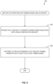
- FIG. 8 is a flowchart that illustrates a method 800 for operating a gas turbine engine (e.g., engines 100a-100e, etc.) used in an aircraft in accordance with teachings disclosed herein.
- the method 800 ensures that a TTB pump (e.g., TTB pumps 602-620, etc.) operates at a pump power that provides an SFC benefit to the gas turbine engine during a cruise phase of flight of the aircraft (e.g., aircraft 10, etc.).
- the method 800 begins at block 802, at which the gas turbine engine provides a fuel flow rate to generate an engine power associated with a cruise condition for the aircraft.
- the gas turbine engine uses the pump to circulate a working fluid (e.g., sCO2, etc.) through a thermal transport bus (e.g., TTB 302, etc.) to heat a fuel in the gas turbine engine.
- a working fluid e.g., sCO2, etc.
- TTB 302, etc. thermal transport bus
- the pump generates a pump power corresponding to the parametric relationship described in connection with FIG. 4 and/or has an exit rotor diameter corresponding to the parametric relationship described in connection with FIG. 5 .
- the gas turbine engine continues providing the fuel flow rate and using the pump until operation of the gas turbine engine of the aircraft during cruise conditions ends.
- TTB thermal transport bus
- TTB thermal management system
- SFC specific fuel consumption
- Disclosed parametric relationships can be used to expedite the design or selection process of the TTB pump for a certain engine thrust class.
- corrected pump power and engine thrust class corrected fuel flow rate
- disclosed parametric relationships between corrected rotor diameter and engine thrust class enables manufacture of a TTB pump to provide an effective mass flow rate of working fluid to improve the SFC (associated with the thrust class) without being oversized.
- the parametric relationship ensures that the TTB pump is not too large so as to outweigh the performance benefits provided.
- example TTB pumps disclosed herein enable improved operability and efficiency of a turbine engine while limiting the size of the TTB pump in the TMS.
- disclosed parametric relationships can determine the pump power for the thrust class that results in a TTB pump that properly sized, such that the TTB pump provides an SFC benefit to engines of the thrust class without negatively affecting the weight of the engines.
- FFR is between 0.05 pounds-mass per second and 3.5 pounds-mass per second.
- FFR is between 3.5 pounds-mass per second and 16 pounds-mass per second.
- NHC fuel net heat of combustion
- c p_fuel first specific heat capacity
- the second specific heat capacity ( c p_pump ) is between 100 foot-pounds-force per pound-mass times degree Rankine and 5000 foot-pounds-force per pound-mass times degree Rankine
- the first density ( ⁇ pump ) is between 0.1 pounds-mass per cubic foot and 100 pounds-mass per cubic foot.
- FFR is between 0.05 pounds-mass per second and 3.5 pounds-mass per second.
- FFR is between 0.05 pounds-mass per second and 3.5 pounds-mass per second.
- P engine is between 1.0e6 foot-pounds-force per second and 1.0e8 foot-pounds-force per second.
- thermo management system of any preceding clause, wherein the pump is a single-stage radial compressor.
- thermo management system of any preceding clause, wherein the pump is a multistage radial compressor.
- thermo management system of any preceding clause, wherein the pump is a single-stage axial compressor.
- thermo management system of any preceding clause wherein the pump is a multistage axial compressor.
- thermo management system of any preceding clause, wherein the pump is a rotary screw compressor.
- thermal management system of any preceding clause, wherein the net heat of combustion ( NHC fuel ) is between 1.0e6 foot-pounds-force per pound-mass and 1.0e8 foot-pounds-force per pound-mass, and wherein the first specific heat capacity ( c P_fuel ) is between 100 foot-pounds-force per pound-mass times degree Rankine and 5000 foot-pounds-force per pound-mass times degree Rankine.
- thermo management system of any preceding clause, wherein the fuel is a hydrocarbon fuel.
- thermo management system of any preceding clause, wherein the second specific heat capacity ( c p_pump ) is between 100 foot-pounds-force per pound-mass times degree Rankine and 5000 foot-pounds-force per pound-mass times degree Rankine, and wherein the first density ( ⁇ pump ) is between 0.1 pounds-mass per cubic foot and 100 pounds-mass per cubic foot.
- the second specific heat capacity ( c p_pump ) is between 100 foot-pounds-force per pound-mass times degree Rankine and 5000 foot-pounds-force per pound-mass times degree Rankine
- first density ( ⁇ pump ) is between 0.1 pounds-mass per cubic foot and 100 pounds-mass per cubic foot.
- thermo management system of any preceding clause wherein the working fluid is supercritical carbon dioxide.
- thermo management system of any preceding clause, wherein the working fluid is liquid helium.
- FFR is between 0.05 pounds-mass per second and 3.5 pounds-mass per second.
- FFR is between 3.5 pounds-mass per second and 16 pounds-mass per second.
- FFR is between 0.25 pounds-mass per second and 15 pounds-mass per second.
- FFR is between 0.05 pounds-mass per second and 3.5 pounds-mass per second.
- FFR is between 3.5 pounds-mass per second and 16 pounds-mass per second.
- NHC fuel net heat of combustion
- c p_fuel first specific heat capacity
Landscapes
- Engineering & Computer Science (AREA)
- Chemical & Material Sciences (AREA)
- Combustion & Propulsion (AREA)
- Mechanical Engineering (AREA)
- General Engineering & Computer Science (AREA)
- Structures Of Non-Positive Displacement Pumps (AREA)
Applications Claiming Priority (1)
| Application Number | Priority Date | Filing Date | Title |
|---|---|---|---|
| US18/167,643 US11952944B1 (en) | 2023-02-10 | 2023-02-10 | Jet engine thermal transport bus pumps |
Publications (2)
| Publication Number | Publication Date |
|---|---|
| EP4414543A2 true EP4414543A2 (de) | 2024-08-14 |
| EP4414543A3 EP4414543A3 (de) | 2024-10-02 |
Family
ID=89853591
Family Applications (1)
| Application Number | Title | Priority Date | Filing Date |
|---|---|---|---|
| EP24155886.5A Withdrawn EP4414543A3 (de) | 2023-02-10 | 2024-02-05 | Wärmetransportbuspumpen für düsentriebwerk |
Country Status (3)
| Country | Link |
|---|---|
| US (1) | US11952944B1 (de) |
| EP (1) | EP4414543A3 (de) |
| CN (1) | CN118481837B (de) |
Family Cites Families (28)
| Publication number | Priority date | Publication date | Assignee | Title |
|---|---|---|---|---|
| GB537473A (en) * | 1939-11-22 | 1941-06-24 | George William Walton | Improvements in or relating to gaseous fluid jet reaction devices or like prime movers |
| US4275557A (en) | 1978-01-25 | 1981-06-30 | General Electric Company | Method and apparatus for controlling thrust in a gas turbine engine |
| US4273304A (en) * | 1979-01-31 | 1981-06-16 | Frosch Robert A | Cooling system for high speed aircraft |
| JPH11344219A (ja) * | 1998-06-01 | 1999-12-14 | Silver Kk | 液体燃料燃焼装置 |
| US6651441B2 (en) * | 2002-01-22 | 2003-11-25 | Hamilton Sundstrand | Fluid flow system for a gas turbine engine |
| US9334802B2 (en) | 2011-10-31 | 2016-05-10 | United Technologies Corporation | Gas turbine engine thermal management system |
| US9915201B2 (en) * | 2013-03-04 | 2018-03-13 | Rolls-Royce Corporation | Aircraft power system |
| US10167732B2 (en) * | 2015-04-24 | 2019-01-01 | Hamilton Sundstrand Corporation | Passive overspeed controlled turbo pump assembly |
| US10260419B2 (en) * | 2015-07-31 | 2019-04-16 | General Electric Company | Cooling system |
| US11021666B2 (en) * | 2015-12-21 | 2021-06-01 | Shell Oil Company | Methods of providing higher quality liquid kerosene based-propulsion fuels |
| US20200224588A1 (en) * | 2019-01-16 | 2020-07-16 | United Technologies Corporation | Work recovery system for a gas turbine engine utilizing a recuperated supercritical co2 bottoming cycle |
| US11286855B2 (en) * | 2019-03-15 | 2022-03-29 | General Electric Company | Systems and methods for operating a turbine engine |
| US11261792B2 (en) * | 2019-11-15 | 2022-03-01 | General Electric Company | Thermal management system with thermal bus for a gas turbine engine or aircraft |
| FR3106625B1 (fr) * | 2020-01-27 | 2022-11-04 | Safran Helicopter Engines | Circuit d’alimentation en carburant d’un moteur d’aéronef |
| WO2021217270A1 (en) * | 2020-05-01 | 2021-11-04 | Walter Jacob Bauer | Liquid treatment system and method |
| US11866668B2 (en) * | 2020-05-19 | 2024-01-09 | Kenneth Losch | Method and system for managing variable, multi-phase fluid conversion to output fuel and energy |
| US11859584B2 (en) * | 2020-06-03 | 2024-01-02 | Hitachi Astemo, Ltd. | Solenoid valve control device |
| JP2021191951A (ja) | 2020-06-05 | 2021-12-16 | 東芝エネルギーシステムズ株式会社 | Co2タービン発電システム |
| EP3974379A1 (de) * | 2020-09-23 | 2022-03-30 | L'air Liquide, Société Anonyme Pour L'Étude Et L'exploitation Des Procédés Georges Claude | Verfahren zum herstellen von reinwasserstoff mit niedrigem dampfexport |
| US11492970B2 (en) * | 2020-12-21 | 2022-11-08 | General Electric Company | Thermal management system with fuel cooling |
| US11795878B2 (en) * | 2021-02-02 | 2023-10-24 | General Electric Company | High-temperature fuel thermal transport bus architecture |
| US11591965B2 (en) * | 2021-03-29 | 2023-02-28 | General Electric Company | Thermal management system for transferring heat between fluids |
| CN115492687B (zh) * | 2021-06-17 | 2025-11-04 | 通用电气公司 | 管理热燃料的控制方法 |
| US20230043809A1 (en) * | 2021-07-29 | 2023-02-09 | General Electric Company | Gas turbine engine having a heat exchanger located in an annular duct |
| US20230076951A1 (en) * | 2021-09-08 | 2023-03-09 | Rolls-Royce North American Technologies Inc. | Electrically driven redundant fuel and oil pumping system for gas turbine engines |
| US20230072590A1 (en) * | 2021-09-08 | 2023-03-09 | Rolls-Royce North American Technologies Inc. | Redundant electrically driven fuel and oil pumping system for gas turbines |
| GB2617309A (en) * | 2021-12-21 | 2023-10-11 | Rolls Royce Plc | Aircraft fuel management |
| KR200496952Y1 (ko) * | 2022-09-28 | 2023-06-20 | 주식회사 파미 | 다단의 재배베드가 구비된 스마트 수경재배장치 |
-
2023
- 2023-02-10 US US18/167,643 patent/US11952944B1/en active Active
-
2024
- 2024-02-05 EP EP24155886.5A patent/EP4414543A3/de not_active Withdrawn
- 2024-02-06 CN CN202410168706.2A patent/CN118481837B/zh active Active
Also Published As
| Publication number | Publication date |
|---|---|
| CN118481837A (zh) | 2024-08-13 |
| EP4414543A3 (de) | 2024-10-02 |
| CN118481837B (zh) | 2025-04-01 |
| US11952944B1 (en) | 2024-04-09 |
Similar Documents
| Publication | Publication Date | Title |
|---|---|---|
| US11022037B2 (en) | Gas turbine engine thermal management system | |
| US11391211B2 (en) | Waste heat recovery system | |
| US20140182264A1 (en) | Aircraft engine systems and methods for operating same | |
| EP4137686B1 (de) | Antriebssysteme für flugzeuge | |
| US10316681B2 (en) | System and method for domestic bleed circuit seals within a turbine | |
| US12448982B2 (en) | Impeller bearings for pumps | |
| CN111140363B (zh) | 具有双分离器泵的燃料氧转换单元 | |
| US12037943B2 (en) | Waste heat recovery system | |
| US11987377B2 (en) | Turbo expanders for turbine engines having hydrogen fuel systems | |
| US20240209789A1 (en) | Oil system | |
| US20260043352A1 (en) | Gas turbine performance | |
| EP4414543A2 (de) | Wärmetransportbuspumpen für düsentriebwerk | |
| US20250334076A1 (en) | Jet engine thermal transport bus pumps | |
| US20240376845A1 (en) | Combustion of fuel | |
| EP4477858A2 (de) | Zwischenkühler für turbinenmotorverdichter | |
| US20240003297A1 (en) | Thermal transport bus capacity for a thermal transport bus in a turbofan engine | |
| US12044170B2 (en) | Closed-loop cooling system for a gas turbine engine | |
| US12234748B2 (en) | Gas turbine engine having outlet guide vanes | |
| US12152492B2 (en) | Sealing system including a seal assembly between components | |
| EP4660432A1 (de) | Verbessertes gegenläufiges turbogebläse | |
| US12158115B2 (en) | Gas turbine engine heat exchange | |
| CN119933858A (zh) | 燃气涡轮发动机中的空气对空气热交换器势 | |
| CN118167480A (zh) | 集成式发动机入口框架空气冷却的油冷却设备 |
Legal Events
| Date | Code | Title | Description |
|---|---|---|---|
| PUAI | Public reference made under article 153(3) epc to a published international application that has entered the european phase |
Free format text: ORIGINAL CODE: 0009012 |
|
| STAA | Information on the status of an ep patent application or granted ep patent |
Free format text: STATUS: THE APPLICATION HAS BEEN PUBLISHED |
|
| AK | Designated contracting states |
Kind code of ref document: A2 Designated state(s): AL AT BE BG CH CY CZ DE DK EE ES FI FR GB GR HR HU IE IS IT LI LT LU LV MC ME MK MT NL NO PL PT RO RS SE SI SK SM TR |
|
| PUAL | Search report despatched |
Free format text: ORIGINAL CODE: 0009013 |
|
| AK | Designated contracting states |
Kind code of ref document: A3 Designated state(s): AL AT BE BG CH CY CZ DE DK EE ES FI FR GB GR HR HU IE IS IT LI LT LU LV MC ME MK MT NL NO PL PT RO RS SE SI SK SM TR |
|
| RIC1 | Information provided on ipc code assigned before grant |
Ipc: F02C 7/224 20060101ALI20240829BHEP Ipc: F02C 7/16 20060101ALI20240829BHEP Ipc: F02C 7/14 20060101ALI20240829BHEP Ipc: F02C 3/22 20060101AFI20240829BHEP |
|
| STAA | Information on the status of an ep patent application or granted ep patent |
Free format text: STATUS: REQUEST FOR EXAMINATION WAS MADE |
|
| 17P | Request for examination filed |
Effective date: 20241230 |
|
| STAA | Information on the status of an ep patent application or granted ep patent |
Free format text: STATUS: EXAMINATION IS IN PROGRESS |
|
| 17Q | First examination report despatched |
Effective date: 20250324 |
|
| STAA | Information on the status of an ep patent application or granted ep patent |
Free format text: STATUS: THE APPLICATION IS DEEMED TO BE WITHDRAWN |
|
| 18D | Application deemed to be withdrawn |
Effective date: 20250725 |