EP4414556A2 - Structure de plaque de blocage pour une efficacité de transmission acoustique améliorée - Google Patents
Structure de plaque de blocage pour une efficacité de transmission acoustique améliorée Download PDFInfo
- Publication number
- EP4414556A2 EP4414556A2 EP24183906.7A EP24183906A EP4414556A2 EP 4414556 A2 EP4414556 A2 EP 4414556A2 EP 24183906 A EP24183906 A EP 24183906A EP 4414556 A2 EP4414556 A2 EP 4414556A2
- Authority
- EP
- European Patent Office
- Prior art keywords
- cavity
- acoustic
- actuator
- matching structure
- blocking plate
- Prior art date
- Legal status (The legal status is an assumption and is not a legal conclusion. Google has not performed a legal analysis and makes no representation as to the accuracy of the status listed.)
- Pending
Links
Images






Classifications
-
- B—PERFORMING OPERATIONS; TRANSPORTING
- B06—GENERATING OR TRANSMITTING MECHANICAL VIBRATIONS IN GENERAL
- B06B—METHODS OR APPARATUS FOR GENERATING OR TRANSMITTING MECHANICAL VIBRATIONS OF INFRASONIC, SONIC, OR ULTRASONIC FREQUENCY, e.g. FOR PERFORMING MECHANICAL WORK IN GENERAL
- B06B1/00—Methods or apparatus for generating mechanical vibrations of infrasonic, sonic, or ultrasonic frequency
- B06B1/02—Methods or apparatus for generating mechanical vibrations of infrasonic, sonic, or ultrasonic frequency making use of electrical energy
- B06B1/06—Methods or apparatus for generating mechanical vibrations of infrasonic, sonic, or ultrasonic frequency making use of electrical energy operating with piezoelectric effect or with electrostriction
- B06B1/0644—Methods or apparatus for generating mechanical vibrations of infrasonic, sonic, or ultrasonic frequency making use of electrical energy operating with piezoelectric effect or with electrostriction using a single piezoelectric element
- B06B1/0662—Methods or apparatus for generating mechanical vibrations of infrasonic, sonic, or ultrasonic frequency making use of electrical energy operating with piezoelectric effect or with electrostriction using a single piezoelectric element with an electrode on the sensitive surface
- B06B1/067—Methods or apparatus for generating mechanical vibrations of infrasonic, sonic, or ultrasonic frequency making use of electrical energy operating with piezoelectric effect or with electrostriction using a single piezoelectric element with an electrode on the sensitive surface which is used as, or combined with, an impedance matching layer
-
- F—MECHANICAL ENGINEERING; LIGHTING; HEATING; WEAPONS; BLASTING
- F04—POSITIVE - DISPLACEMENT MACHINES FOR LIQUIDS; PUMPS FOR LIQUIDS OR ELASTIC FLUIDS
- F04B—POSITIVE-DISPLACEMENT MACHINES FOR LIQUIDS; PUMPS
- F04B43/00—Machines, pumps, or pumping installations having flexible working members
- F04B43/02—Machines, pumps, or pumping installations having flexible working members having plate-like flexible members, e.g. diaphragms
- F04B43/04—Pumps having electric drive
- F04B43/043—Micropumps
- F04B43/046—Micropumps with piezoelectric drive
-
- F—MECHANICAL ENGINEERING; LIGHTING; HEATING; WEAPONS; BLASTING
- F04—POSITIVE - DISPLACEMENT MACHINES FOR LIQUIDS; PUMPS FOR LIQUIDS OR ELASTIC FLUIDS
- F04B—POSITIVE-DISPLACEMENT MACHINES FOR LIQUIDS; PUMPS
- F04B45/00—Pumps or pumping installations having flexible working members and specially adapted for elastic fluids
- F04B45/04—Pumps or pumping installations having flexible working members and specially adapted for elastic fluids having plate-like flexible members, e.g. diaphragms
- F04B45/047—Pumps having electric drive
-
- G—PHYSICS
- G10—MUSICAL INSTRUMENTS; ACOUSTICS
- G10K—SOUND-PRODUCING DEVICES; METHODS OR DEVICES FOR PROTECTING AGAINST, OR FOR DAMPING, NOISE OR OTHER ACOUSTIC WAVES IN GENERAL; ACOUSTICS NOT OTHERWISE PROVIDED FOR
- G10K11/00—Methods or devices for transmitting, conducting or directing sound in general; Methods or devices for protecting against, or for damping, noise or other acoustic waves in general
- G10K11/02—Mechanical acoustic impedances; Impedance matching, e.g. by horns; Acoustic resonators
-
- G—PHYSICS
- G10—MUSICAL INSTRUMENTS; ACOUSTICS
- G10K—SOUND-PRODUCING DEVICES; METHODS OR DEVICES FOR PROTECTING AGAINST, OR FOR DAMPING, NOISE OR OTHER ACOUSTIC WAVES IN GENERAL; ACOUSTICS NOT OTHERWISE PROVIDED FOR
- G10K9/00—Devices in which sound is produced by vibrating a diaphragm or analogous element, e.g. fog horns, vehicle hooters or buzzers
- G10K9/18—Details, e.g. bulbs, pumps, pistons, switches or casings
- G10K9/22—Mountings; Casings
-
- H—ELECTRICITY
- H04—ELECTRIC COMMUNICATION TECHNIQUE
- H04R—LOUDSPEAKERS, MICROPHONES, GRAMOPHONE PICK-UPS OR LIKE ACOUSTIC ELECTROMECHANICAL TRANSDUCERS; ELECTRIC HEARING AIDS; PUBLIC ADDRESS SYSTEMS
- H04R1/00—Details of transducers, loudspeakers or microphones
- H04R1/02—Casings; Cabinets ; Supports therefor; Mountings therein
- H04R1/025—Arrangements for fixing loudspeaker transducers, e.g. in a box, furniture
-
- H—ELECTRICITY
- H04—ELECTRIC COMMUNICATION TECHNIQUE
- H04R—LOUDSPEAKERS, MICROPHONES, GRAMOPHONE PICK-UPS OR LIKE ACOUSTIC ELECTROMECHANICAL TRANSDUCERS; ELECTRIC HEARING AIDS; PUBLIC ADDRESS SYSTEMS
- H04R1/00—Details of transducers, loudspeakers or microphones
- H04R1/20—Arrangements for obtaining desired frequency or directional characteristics
- H04R1/22—Arrangements for obtaining desired frequency or directional characteristics for obtaining desired frequency characteristic only
- H04R1/28—Transducer mountings or enclosures modified by provision of mechanical or acoustic impedances, e.g. resonator, damping means
- H04R1/2807—Enclosures comprising vibrating or resonating arrangements
- H04R1/2811—Enclosures comprising vibrating or resonating arrangements for loudspeaker transducers
Definitions
- the present disclosure relates generally to improving acoustic transmission efficiency by incorporating acoustic matching structures into acoustic transducers.
- Acoustic transducers convert one form of energy, typically electrical, into acoustic (pressure) waves.
- the proportion of energy that is emitted from the transducer into the surrounding acoustic medium depends on the acoustic impedance of the medium relative to the transducer.
- the impedances should be close to equal.
- the acoustic medium will be air or another gaseous medium, which, typically, has an acoustic impedance several orders of magnitude lower than that of the transducing element. This large impedance mismatch leads to poor transmission of energy into the acoustic medium, limiting the amount of acoustic energy emitted by the transducer.
- Techniques to improve the transmission efficiency involve adding a matching layer, or matching structure, between the transducer and acoustic medium.
- This application describes an acoustic matching structure used to increase the transmission efficiency of an acoustic transducer when emitting into a medium that has an acoustic impedance significantly lower than that of the transducer.
- the transducer consists of an acoustic matching structure and a transducing element.
- the acoustic matching structure is passive and is designed to improve the efficiency of acoustic transmission from the transducing element to a surrounding acoustic medium.
- the transducing element generates acoustic output when driven with an electrical input.
- the transduction mechanism may be by oscillating motion, for example using an electromechanical actuator, or by oscillating temperature, for example, using an electrothermal transducer.
- an acoustic matching structure is used to increase the power radiated from a transducing element with a higher impedance into a surrounding acoustic medium with a lower acoustic impedance.
- the acoustic matching structure consists of a resonant acoustic cavity bounded by an acoustic transducing element and a blocking plate.
- the resonant acoustic cavity amplifies pressure oscillations generated by the transducing element and the blocking plate contains one or more apertures, which allow pressure oscillations to propagate from the resonant acoustic cavity into the surrounding acoustic medium.
- a preferred embodiment of the acoustic matching structure consists of a thin, substantially planar cavity bounded by a two end walls and a side wall.
- the end walls of the cavity are formed by a blocking plate wall and a transducing element wall separated by a short distance, less than one quarter of the wavelength of acoustic waves in the surrounding acoustic medium at the operating frequency of the transducer.
- the end walls and side wall bound a cavity with diameter approximately equal to half of the wavelength of acoustic waves in the surrounding acoustic medium.
- a transducing element generates acoustic oscillations in the fluid in the cavity.
- the transducing element may be an actuator which generates motion of an end wall in a direction perpendicular to the plane of the cavity to excite acoustic oscillations in the fluid in the cavity, and the cavity causes resonant amplification of the resulting pressure oscillation.
- the cavity side wall or end walls contain at least one aperture positioned away from the center of the cavity to allow pressure waves to propagate into the surrounding acoustic medium.
- a transducing element directly refers to the portion of the structure that converts energy to acoustic energy.
- An actuator refers to the portion of the solid structure that contains the kinetic energy before transferring it to the medium.
- the acoustic impedance of a resonant piezoelectric bending actuator has been analyzed for a 40kHz actuator ( Toda, IEEE Transactions on Ultrasonics, Ferroelectrics, and Frequency Control, Vol. 49, No. 7, July 2002 ) giving Z 1 ⁇ 2 ⁇ 10 4 kg ⁇ m -2 ⁇ s -1 .
- this resonant bending actuator has a much lower acoustic impedance than the bulk materials from which it is constructed (PZT and aluminum), there remains a substantial difference between the actuator impedance and air impedance, decreasing efficiency and acoustic output.
- a solution to this problem is to add an acoustic matching layer with an impedance Z 2 which serves as an intermediary between the higher-impedance actuator and the lower-impedance bulk gaseous phase medium.
- An acoustic matching layer or other acoustic matching structure is required to be inserted into the path of acoustic energy transfer from the actuator into the medium and is designed to have an acoustic impedance that is as close as possible to the optimal matching structure impedance, that is the geometric mean of the acoustic impedances of the source and the destination, which in some embodiments may be a higher-impedance actuator and the lower-impedance bulk air or other acoustic medium.
- the effect of the intermediate impedance matching layer is that the energy transfer from the higher impedance region to the matching layer and then from the matching layer to the lower impedance region is more efficient than the more direct energy transfer from the higher to the lower impedance regions.
- Figure 1 shows a schematic 100 of a transducer that includes a conventional matching layer.
- An intermediate layer 130 (with an intermediate acoustic impedance) serves as the matching layer which is added between the actuator 140 and acoustic medium 110 (such as air).
- the thickness 120 of the intermediate layer 130 is approximately equal to a quarter wavelength of the longitudinal pressure waves in the matching layer at the operating frequency when the matching layer is considered as a bulk material.
- Figure 2 is a graph 200 showing calculated acoustic impedance 210 of an acoustic matching structure constructed from a plate of thickness t 220 containing an array of holes, as described in the prior art ( Toda, IEEE Transactions on Ultrasonics, Ferroelectrics, and Frequency Control, Vol. 49, No. 7, July 2002 ). Variation of acoustic impedance with plate thickness is calculated in air for frequencies of 30kHz, 40kHz and 50kHz (250, 240, 230), showing impedance maxima when the plate thickness is equal to 1 ⁇ 4 of the acoustic wavelength of air.
- FIGs 3, 4 and 5 are graphs 300, 400, 500 showing calculated acoustic impedance of a thin film matching layer, as described in the prior art referenced in the previous paragraph.
- acoustic impedance 310 is plotted against frequency 320 for the case of a 15 ⁇ m thick polyethylene film spaced away from a transducing element by an air gap with thickness from 0.1mm to 0.5mm (370, 360, 350, 340, 330).
- acoustic impedance 410 is plotted against frequency 420 for a range of film thickness values from 5 ⁇ m to 45 ⁇ m (470, 460, 450, 440, 430), with the film separated by an air gap of 0.2mm from a transducing element.
- acoustic impedance 510 is plotted against separation between film and transducing element 520 for a film thickness of 25 ⁇ m.
- the combination of thin film and thin air gap creates a high acoustic impedance 530 when the gap is approximately 20-22 ⁇ m.
- Figure 6 is a cross-section of a transducer including a Helmholtz resonator.
- the Helmholz resonator 600 has a cavity 640 with dimensions substantially less than 1 ⁇ 4 of the acoustic wavelength and spatially uniform pressure, and an aperture 650 typically located at the center of the cavity 640.
- the cavity is bounded by walls 610a, 610b, 620a, 620b.
- the acoustic impedance of a matching layer for a thickness-mode, piezoelectric actuator operating in air may be computed.
- the acoustic impedance required in this situation is approximately 100,000 kg ⁇ m -2 ⁇ s -1 .
- the computation proceeds by taking logarithms of each of the impedances of the adjoining elements, which is found to be approximately 7.5 for the piezoelectric transducing element ( Z 1 ) and approximately 2.5 for the bulk air ( Z 3 ) at the expected temperature and pressure. Then, for each matching layer required the average of the logarithms of the impedances of the adjoining regions may be used to determine the logarithm of the impedance required for the matching layer.
- Table 1 Material Acoustic Impedance kg ⁇ m -2 ⁇ s -1 Impedance logarithm PZT 5A 34,000,000 7.53 Air (1 atm, 20°C) 400 2.60 Ideal matching layer 100,000 5.00
- the acoustic impedances required for an ideal matching layer to bridge this large gap in acoustic impedances must be therefore composed of a solid material with a very low speed of sound and low density.
- the low speed of sound is preferable in order to reduce the size or volume of material required to make a matching layer that fits the quarter wavelength criterion.
- the low density is required for the material to have an acoustic impedance that is appropriate to a matching layer.
- suitable materials do not occur naturally. They must be often constructed with special manufacturing processes that tend to be complex and difficult to control, leading to variable acoustic properties and variable performance as a matching layer.
- matching layers using glass and resin microspheres are described in US Patent No.
- a further problematic issue with low-density, low-speed-of-sound matching layers of suitable materials is the constraint on thickness imposed by the quarter wavelength requirement.
- the wavelength at 40 kHz in air at ambient pressure and temperature is 8.58 mm. Therefore, assuming the material has a similar speed of sound to that of air-which would itself be difficult to achieve as it would require a high-density but low-stiffness material which would again likely require a specialist process to create-an ideal matching layer would have a thickness close to 2.14 mm. In thickness-constrained applications, this may be too great to be viable, either commercially or for the particular application of interest. Matching layers made of a material with a speed of sound greater than air would need to be thicker than this 2.14 mm.
- This invention proposes the use of a vented resonant acoustic cavity formed by placing a blocking plate in the path of the acoustic energy transfer from a transducing element to an acoustic medium to achieve an intermediate acoustic impedance, that is lower acoustic impedance than that of the transducing element and higher acoustic impedance than the surrounding acoustic medium.
- the intermediate acoustic impedance increases the efficiency of acoustic energy transfer from the transducing element to the acoustic medium, and is provided through the production of a controlled resonant acoustic mode in an acoustic cavity in the path of the transfer of acoustic energy from the transducing element to the acoustic medium.
- the acoustic cavity that constrains the acoustic medium in a way that gives rise to a resonant acoustic mode in the acoustic medium that can be excited by the transducing element.
- the blocking plate which forms one face of the acoustic cavity contains apertures that allow acoustic energy to be transmitted from the acoustic cavity into the acoustic medium.
- the actuator creates a boundary velocity field in the acoustic medium and is situated on one side of the blocking plate which is placed intentionally in the path of the energy transfer.
- the actuator and blocking plate form an acoustic cavity substantially bounded by the actuator and the blocking plate.
- the actuator drives an acoustic wave from the surface of the actuator into the acoustic cavity.
- resonant acoustic oscillations in the cavity are excited and build in amplitude.
- the resonant increase in acoustic pressure resulting from substantially constant actuator oscillation velocity amplitude indicates an increase in the effective acoustic impedance of the acoustic cavity relative to the bulk acoustic medium by a factor of Q cavity , where Q cavity is the quality factor of the cavity acoustic resonance.
- the dimensions can also be arranged and resized so that the close spacing of the blocking plate and actuator increases the effective acoustic impedance of the acoustic medium by confining the fluid to a thin layer and constraining the fluid motion to be substantially parallel to the face of the actuator.
- r cavity > 5 h cavity so that f geom > 2.5, and more preferably, r cavity > 10 h cavity so that f geom > 5.
- the acoustic impedance of the fluid in the cavity is increased relative to the bulk acoustic medium by a factor: Q cavity ⁇ f geom , the product of the resonant cavity quality factor and the geometric amplification factor.
- the acoustic cavity acts as an acoustic matching layer with acoustic impedance higher than the bulk acoustic medium and lower than the actuator.
- the optimal cavity height results from a tradeoff between maximizing the geometric amplification factor, and maximizing the cavity quality factor by minimizing the viscous losses in the boundary layers.
- an aperture is needed to allow acoustic waves to escape from the structure. It is helpful to balance the constraints of the maintenance and conservation of the appropriate acoustic perturbation, wherein a smaller area aperture in the novel matching structure is beneficial, which the requirement that the increased perturbation be transmitted onwards into the acoustic medium, wherein a larger area aperture in the novel matching structure is beneficial. At least some aperture, which may comprise one or many discrete sections, must be added so that a portion of the acoustic output generated by the transducer can escape on every cycle into the bulk medium.
- the term "acoustic medium” refers to the medium inside the cavity through which acoustic waves travel.
- the "bulk medium” refers to the acoustic medium which exists outside the cavity.
- the medium can be liquid, such as water, or gas, such as air or any other medium which is distinct from the construction material of the invention. Any medium supporting acoustic waves can be referred to as a "fluid" for the purposes of this discussion.
- a simple structure can embody the properties described above in the form of an acoustic cavity consisting of a volume of the acoustic medium which has in this example been restricted by a surrounding structure of side walls.
- p is the complex-valued acoustic pressure
- c 0 is the speed of sound in the ambient medium
- ⁇ is the acoustic angular frequency
- t time
- j ⁇ 1
- k is the wavenumber.
- ⁇ lmn c 0 k xl 2 + k ym 2 + k zn 2
- the amplitude of the wave ( A lmn ) scales with input but in this analysis has no effect on the frequency of the mode.
- Aperture(s) which allow acoustic energy to propagate from the cavity to the surrounding acoustic medium are located in areas of lower pressure oscillation amplitude, and transducing elements are located in areas of higher pressure oscillation amplitude.
- a tall, thin cavity can be designed with a high-pressure antinode occurring near the actuator. This may be beneficial in applications in which compacting larger numbers of transducers in a small surface area is required, but thickness restrictions are relaxed instead.
- L z L.
- these antinodes are out of phase and swap every half period of the progressive wave mode present in the cavity.
- a single actuator could be situated such that during one phase of its motion it applies displacement into one antinode of the structure and during the opposite phase excites motion at the other antinode. This could be accomplished through mechanical coupling to a flexible surface at the second antinode location. Alternatively, a small pocket of gas could provide coupling to a flexible surface.
- the actuator could be designed to operate in an 'S'-shaped mode where half is moving into the structure and half is moving out during one polarity of drive which reverses at the other polarity. This would then be matched to a structure containing out-of-phase antinodes at the surfaces of maximum displacement.
- the example cavities described in the previous two paragraphs describe tubular-shaped embodiments of the invention with one primary dimension extending longer than the other two.
- An advantage of this arrangement is that the cavity need not extend directly normal to the transducing element but can curve if necessary. This acts like a waveguide to direct and steer the acoustic wave while still developing the mode structure necessary to be an effective matching layer.
- the effective cavity cross-section which helps maintain the acoustic mode will follow the acoustic wave-front through the cavity.
- An estimate of the path of the cavity mode can be made by connecting an imaginary line from the center of the transducing element to center of the blocking plate through the cavity while maximizing the average distance at any point on the line to the side walls. Taking cross sections using this line as a normal can adequately estimate the mode structure.
- Bending and altering the cavity cross section can, for instance, enable shrinking the effective spacing in an array arrangement. This could be done by arranging a network of matching cavities from an array of transducers with a given pitch and reducing and skewing the opposite blocking plate side of the cavity so that the pitch is narrower on the aperture side. This embodiment could also be used to change the effective array arrangement from, for example, rectilinear to hexagonal packing.
- An embodiment of this perturbation of ⁇ may be realized by modifying the geometry internal cavity from a square prism to a rectangular prism, wherein the deviation from a square prism is indicative of the separation of the two resonant peaks.
- these peaks When these peaks are close together, they may be considered as a de facto single (but potentially broader) peak. When these ⁇ deviate, it has the effect of broadening the resonant peak of the output, enabling reduced manufacturing tolerances to be used or allowing the driven frequency to vary from the resonant frequency without experiencing sharp loss of output. This broader response is at the expense of reduced output at the peak frequency.
- a similar analysis can be done for an arbitrary shaped structure or cavity. Some, like a cylindrical cavity, can be solved analytically in a way that is similar to the previous examples, while others will need the help of numerical simulations such as finite element analysis to predict where, when and how the appropriate high-pressure antinodes will form.
- the design goal is to have an acoustic mode which yields a pressure distribution that spatially mimics the displacement of the actuator mounted in the acoustic transducer structure at the desired frequency of oscillation.
- apertures should ideally be added to the surface of the resonant cavity to allow a portion of the acoustic field in the cavity to escape into the bulk medium on every cycle.
- the exact shape and placement of the apertures does not lend itself to closed-form analytic analysis.
- the size should be kept small compared to the larger length dimensions of the mode in the cavity so that they do not substantially disturb the cavity mode; apertures that are too large will cause a significant loss of acoustic pressure in the cavity and will cause the desired impedance effect to wane. Too small, however, and not enough acoustic pressure will escape per cycle therefore reducing the efficacy of the cavity as a matching layer.
- An aperture shape which substantially corresponds to an equiphasic portion of the acoustic mode shape will also help prevent significant disturbance of the mode shape.
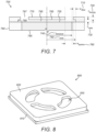
- FIG. 7 shows a schematic 700 of a transducer coupled to a blocking plate in cross section, which serves to illustrate an embodiment of the invention.
- a blocking plate structure includes a blocking plate 770 with a side wall 780 and aperture(s) 797. This is situated spaced away from an acoustic transducing element 785 with a surrounding structure 790.
- the blocking plate is spaced a distance, h cavity 730, in the propagation direction away from the transducing element front face, where h cavity 730 is less than one quarter of the wavelength of acoustic waves in the surrounding medium at the operating frequency.
- the underside surface of the blocking plate 770 i.e.
- transducing element forms one surface of a thin, planar acoustic cavity, with the spatial extent of the cavity formed by the propagation face of the transducing element 765, the blocking plate 755, and the side walls 790.
- Operation of the transducing element excites a substantially radial acoustic resonance in the cavity 795 travelling parallel to the blocking plate, which increases the pressure experienced by the front face of the transducing element during the compression phase of its operation as this pressure here is substantially the sum of the ambient pressure and the maximum pressure perturbation due to the resonant mode.
- the cavity 795 has one or more apertures 797 positioned on the outer surface facing the bulk medium away from its centerline to allow acoustic pressure waves to propagate into the surrounding medium.
- the aperture(s) 797 is formed by the opening between the blocking plate 770 and the side wall 780.
- the nominal parameter values for 20kHz, 65 kHz and 200kHz embodiments of the transducer shown in Figure 7 are set forth in Table 2.
- Example transducer dimensions (mm) 20 kHz 65 kHz 200 kHz r actuator 740 7.50 2.50 0.80 r cavity 750 7.50 2.50 0.80 w outlet 760 2.00 0.80 0.20 w offset 710 0.00 0.00 0.00 h cavity 730 0.25 0.20 0.10 h blocking 720 0.25 0.20 0.10
- the blocking plate structure forms a cavity 795 positioned immediately next to the actuating face of the acoustic transducing element assembly which represents the primary transfer surface for moving kinetic energy into the acoustic medium.
- the acoustic resonant frequency of this cavity in this embodiment is chosen to match the substantially radial mode to increase the power radiated by the transducer into the propagation medium. This is possible because the small cavity 795 between the transducing element and the blocking front plate of Figure 7 increases the amplitude of pressure oscillation generated within that cavity 795 by the motion of the transducer.
- This acoustic power propagates into the surrounding medium via the one or more aperture(s) 797.
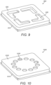
- Aperture examples are shown in Figures 8 , 9 and 10 .
- Figure 8 shows a schematic 800 with a transducing element 810 coupled to an acoustic structure whose upper surface 820 has annular-shaped apertures 830.
- Figure 9 shows a schematic 900 with a transducing element 910 coupled to an acoustic structure whose upper surface 920 has non-annular-shaped apertures 930.
- Figure 10 shows a schematic 1000 with a transducing element 1010 coupled to an acoustic structure whose upper surface 1020 has circular apertures 1030 positioned on a circular pitch.
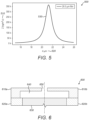
- Figures 11 and 12 demonstrate with experimental data and numerical simulation respectively that, over a certain frequency range, both on-axis acoustic pressure and radiated acoustic power in this L x « L y » L Z design are greater with the use of the blocking plate structure that embodies the invention than without.
- Figure 11 shows a graph 1100 of the measured on-axis acoustic pressure with and without the embodied invention.
- the x-axis 1120 is frequency in Hz.
- the y -axis 1110 is the on-axis acoustic pressure at 30 cm in Pa.
- the plot shows the on-axis acoustic pressure measured 30 cm from the transducer as a function of frequency for a transducer with the acoustic structure which embodies the invention 1130 and without this structure 1140.
- the graph 1100 shows that, for almost all frequencies between 50 kHz and 80 kHz, the on-axis acoustic pressure at 30 cm is higher for a transducer with a blocking plate that embodies the invention than without.
- the on-axis acoustic pressure is significantly higher when the blocking plate structure in used between about 62 kHz to about 66 kHz in this embodiment.
- Figure 12 shows a graph 1200 of the simulated on-axis acoustic power with and without the blocking plate.
- the x-axis 1220 is frequency in Hz.
- the y -axis 1210 is radiated power in W.
- the plot shows radiated power as a function of frequency for a transducer with the blocking plate 1230 and without the blocking plate 1240.
- the graph 1200 shows that, for frequencies between about 60 kHz and about 90 kHz, the radiated power is significantly higher with the blocking plate than without.
- the frequency of the acoustic resonance of the cavity may provide desirable characteristics of the acoustic output (e.g. broadband, high on-axis pressure, high radiated acoustic power).
- the transducing element operating frequency may be different from the acoustic resonant frequency.
- the radiated acoustic power is greatest.
- a further performance improvement may be realized if the transducing element and acoustic cavity resonance are mode-shape matched, i.e. the displacement profile of the transducing element oscillation is substantially similar to the pressure mode shape of the acoustic resonance excited in the medium.
- Figure 13 shows a graph 1300 of the magnitude of pressure oscillations at the propagation face of transducers with and without a blocking plate (which is part of a structure that is the embodiment) in an axisymmetric simulation.
- the blocking plate and side walls are circularly symmetric.
- the x-axis 1320 is the distance in mm of the radial line on the transducer face starting from the center.
- the y -axis 1310 is the absolute acoustic pressure in Pa.
- the data shown is taken from an axisymmetric pressure acoustics finite element model (COMSOL) for two otherwise identical piston mode actuators.
- COMPOSOL axisymmetric pressure acoustics finite element model
- Figure 14A shows a schematic 1400 of a cross-section embodiment of a blocking plate when coupled to a bending-mode piezoelectric actuator.
- the blocking plate structure includes a blocking plate 1420, side walls 1450 and aperture(s) 1490, mounted using a supporting structure 1410a, 1410b, and spaced away from an acoustic actuator comprising a substrate 1430 and a piezoelectric transducing element 1440.
- Figure 14B is a graph 1492 showing the radial dependence of the pressure oscillation within the resonant acoustic cavity.
- Figure 14C is a graph 1494 showing the radial dependence of the bending-mode actuator velocity.
- the displacement profile of the actuator is well-matched to the radial mode acoustic pressure distribution in the cavity.
- the blocking plate structure is used to define the motion of the actuator as well as the geometry of the cavity.
- the blocking plate structure heavily constrains motion of the actuator at the perimeter of the cavity where the structure becomes substantially stiffer, owing to the greater thickness of material in this region.
- the structure similarly does not constrain motion at the center of the actuator where the center of the cavity and thus the high-pressure antinode is located. This allows the displacement of the actuator to follow the desired bending shape when actuated, which is very similar in profile to the acoustic pressure distribution depicted in Figure 13 . Consequently, the blocking plate serves a dual function: providing mechanical support for the actuator and creating an acoustic matching structure. This further reduces the height of the whole system.
- the cavity resonance can be tuned by changing the cavity radius, r cavity 750. This can be different than the transducing element radius r transducer 740, This allows the transducing element to be designed separately from the cavity, since the resonant frequency of the cavity, f acoustic , varies as f acoustic ⁇ 1 r cavity .
- Table 3 below shows example dimensions to tune to cavity to 3 different frequencies of operation.
- the transducing element radius and cavity radius are typically chosen to be the same.
- Table 3 shows that the r cavity 750 can be either sub-wavelength or greater than a wavelength, while still increasing the radiated acoustic power over a transducing element with no blocking plate.
- Table 3 r cavity (mm) w aperture (mm) Frequency at peak output (Hz) Corresponding wavelength (mm) Comment 1.5 0.05 44,500 7.7
- Table 3 shows that, for a given blocking plate and supporting structure thickness h blocking 720 and cavity height h cavity 730 (both 0.2 mm), radiated power can be increased by a cavity with radius either substantially smaller than or greater than the target wavelength.
- Data is taken from a two-dimensional axisymmetric simulation about the centerline of the transducer using a pressure acoustics finite element model (COMSOL).
- COMPOSOL pressure acoustics finite element model
- FIG. 15 is a graph 1500 showing radiated power dependence on the width of w aperture and frequency.
- the x-axis 1520 is frequency in Hz.
- the y -axis 1510 is radiated power in W.
- a baseline 1525 without blocking plate is shown for comparison.
- the graph 1500 shows that a w aperture of 0.1 mm produces the highest radiated power of 0.040 W at a frequency of about 50 kHz. No other w aperture produces a radiated power greater than 0.020 W at any tested frequency.
- Data was taken from a two-dimensional axisymmetric simulation about the centerline of the transducer using a pressure acoustics finite element model (COMSOL) where the transducing element is considered to be a simple piston moving at a preset velocity at each frequency.
- COMPOL pressure acoustics finite element model
- the central region must still be partially blocked by the blocking front plate, such that the width of the aperture, w aperture ⁇ 0.9 r cavity . Yet there also exists a lower limit on the width of the outlet, relating to the oscillatory boundary layer thickness, ⁇ ⁇ ⁇ ⁇ f (where v is the kinematic viscosity of the medium), at the operating frequency, f , such that w aperture > 2 ⁇ . Below this value, a significant proportion of the acoustic energy is lost via viscous dissipation at the outlet.
- Figure 16 is a graph 1600 of the effect of cavity height on the frequency response of the acoustic energy radiated through the blocking plate structure into the medium.
- the x-axis 1620 is frequency in Hz.
- the y -axis 1610 is radiated power in W.
- the plot shows radiated power of the transducer as a function of the frequency at h cavity of 50 ⁇ m 1630, 100 ⁇ m 1640, 150 ⁇ m 1650, and 200 ⁇ m 1660.
- the graph shows that the functions for h cavity of 100 ⁇ m 1640, 150 ⁇ m 1650, and 200 ⁇ m 1660 are quite similar.
- Data for Figure 16 is modeled spectra from a two-dimensional axisymmetric simulation about the centerline of the transducer using a pressure acoustics finite element model of a piston transducer coupled with the blocking plate.
- Table 4 Frequency (Hz) Baseline radiated power (mW) Radiated power with blocking (mW) Power increase (dB) aperture width (mm) 10,000 0.4 0.5 0.5 0.05 12,900 0.7 0.9 0.9 0.05 16,700 1.2 1.8 1.6 0.05 21,500 2.0 4.1 3.1 0.05 27,800 3.3 14.7 6.5 0.05 35,900 4.7 39.9 9.3 0.10 46,400 5.5 18.5 5.3 0.50 59,900 5.1 19.0 5.7 0.50 77,400 4.4 13.3 4.8 1.00 100,000 4.8 13.9 4.6 1.50 129,000 4.4 4.8 0.4 2.00 167,000 4.3 5.3 0.9 2.00 215,000 3.8 3.8 0.0 2.40
- COMPOSOL pressure acoustics finite element model
- a similarly lower limit on the cavity height exists as with the aperture channel width, namely that the viscous penetration depth places a rough lower limit on the cavity size, namely h cavity > 2 ⁇ , for identical reasoning to before.
- An upper bound on the cavity height is also required to ensure the dominant acoustic resonant mode is the designed radial mode. This requires h cavity ⁇ ⁇ 4 , where ⁇ is the acoustic wavelength at the transducer operating frequency.
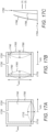
- Figures 17 and 18 relate to transducers using an alternative longitudinal embodiment of the acoustic matching structure, in which the radius of the acoustic cavity is smaller than the height of the acoustic cavity.
- Figure 17A shows an axisymmetric view of a transducer.
- An actuator, 1710 mates to one end of a hollow tube, 1750, at its perimeter.
- a blocking plate, 1720 then mates with the opposite end of the tube.
- An acoustic cavity, 1740 is formed by the combination of the actuator, tube, and blocking plate.
- the frequency of these pressure oscillations can be adjusted so that a longitudinal acoustic resonance is excited in the cavity, increasing their amplitude.
- This resonant frequency will principally be dependent on the cavity's height, the radius of the cavity will have a smaller effect.
- Figure 17B shows an axisymmetric view of a transducer.
- a hollow cylindrical actuator, 1760 mates to a base, 1770, at one end.
- a blocking plate, 1720 then mates with the opposite end of the actuator.
- An acoustic cavity, 1740 is formed by the combination of the actuator, base, and blocking plate.
- Radial motion of the actuator indicated by 1765 generates longitudinal pressure waves in the cavity.
- the frequency of these pressure oscillations can be adjusted so that a longitudinal acoustic resonance is excited in the cavity, increasing their amplitude. This resonant frequency will principally be dependent on the cavity's height, the radius of the cavity will have a smaller effect.
- This configuration has the advantage of providing the actuator with a larger surface area which enables higher acoustic output than the configuration shown in Figure 17A .
- Figure 17C shows how the amplitude of pressure oscillations 1784 in the cavity varies along the longitudinal axis 1782, from the actuator to the aperture, for two cases: (A) with the blocking plate present 1786 (B) without the blocking plate present 1788.
- a first-order acoustic resonance is excited where the amplitude of pressure oscillations reduces monotonically from the closed to the open end of the tube.
- the amplitude is materially higher for the case where the blocking plate is present, and notably so at the aperture where the pressure waves radiate into the surrounding medium.
- the actuator may be a thickness-mode piezoelectric actuator, where, once driven, its motion is approximately uniform and in-phase across its area. It is this motion that generates longitudinal pressure waves in the cavity.
- Figure 18A shows an axisymmetric view of a transducer.
- An actuator, 1810 mates to one end of a hollow tube, 1850, at its perimeter.
- a blocking plate, 1820 then mates with the opposite end of the tube.
- An acoustic cavity, 1840 is formed by the combination of the actuator, tube, and blocking plate.
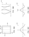
- Figure 18B is a graph 1870 that shows how the phase of pressure oscillations varies along three parallel axes, A, B, and C. Along each axis, the pressure is highest close to the actuator but is out of phase with the pressure at the opposite end of the tube. There is no aperture positioned along axis B as pressure radiated from an aperture at this position would be out of phase with the pressure radiated from apertures 1830 and 1860, which would cause destructive interference and lower the transducer's total pressure output.
- the phase of pressure oscillations varies in the longitudinal and radial directions. In the radial direction, at a given z height, the pressure at the center of the cavity is out of phase with the pressure close to the tube's inner circumference as shown in the graph 1880 of Figure 18C .
- Figure 18D shows the velocity profile 1890 of an actuator that is mode-shape matched to the acoustic resonance described, where the phase of the actuator's oscillations varies across its radius; in-phase at its center, and out-of-phase close to its perimeter.
- a bending-mode piezoelectric actuator could be used to generate such a velocity profile.
- Figure 19A shows a transducer comprising an actuator and a matching structure that is a combination of the blocking plate and thin film matching structures.
- the thin film, 1950 is spaced a short distance away from the actuator, 1910, to a form a sealed acoustic cavity, 1940.
- the blocking plate 1930 is spaced a short distance from the opposite side of the thin film, to form a separate acoustic cavity 1960 with aperture 1920.
- the combination of the two matching structures may improve the acoustic transmission efficiency of the transducer.
- Figure 19B shows a transducer comprising an actuator and a matching structure that is a combination of the blocking plate 1930 and thin film 1950 matching structures.
- the positions of the blocking plate 1930 and thin film 1950 are reversed, such that it is the blocking plate 1930 that is closest to the actuator, and the thin film 1950 radiates pressure directly into the surrounding medium.
- the thin film is positioned a short distance away from the blocking plate 1930 by a spacer element, 1970.
- Figure 19C shows two neighboring transducers 1992, 1194, each with the same configuration as in figure 19B , but with a continuous thin film 1950 shared between the two transducers. This may be advantageous if arrays of transducers are being manufactured as the thin film 1950 could be laminated to the transducer array as a final assembly without requiring further processing.
- Figure 20A shows a transducer comprising an actuator, 2010, and the blocking plate matching structure.
- the blocking plate, 2020 has a thickness that is approximately one quarter of a wavelength of the pressure oscillations in the acoustic medium.
- this medium may be air. Therefore, the aperture, 2030, has a length equal to one quarter of a wavelength.
- a longitudinal acoustic resonance could be excited in the aperture, in addition to the radial resonance excited in the cavity, 2040, formed by the actuator and blocking plate. This additional longitudinal resonance could amplify the pressure output further.
- Figure 20B shows two transducers 2061, 2062, each comprising an actuator and a blocking plate matching structure, with a separate perforated plate, 2060, arranged in front of both transducers.
- the additional perforated plate may act as an additional matching structure and further improve the efficiency of acoustic transmission. It may also act as a protective barrier against, for example, accidental damage to the transducers, or dirt ingress into them.
- Figure 20C shows a transducer comprising an actuator and matching structure that is a combination of the blocking plate 2020 and perforated plate 2060 matching structures.
- the perforated plate 2060 is spaced a short distance from the actuator 2010.
- the blocking plate 2020 is spaced a short distance from the opposite side of the perforated plate, forming a cavity 2040 with an aperture 2030.
- the combination of the two matching structures may improve the acoustic transmission efficiency of the transducer.
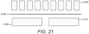
- Figure 21 shows two actuators 2109, 2110, arranged close to one another, with a continuous thin film, 2150, positioned in front of them, and a continuous perforated plate, 2160, positioned in front of that.
- the combination of the two matching structures may improve the acoustic transmission efficiency of the transducer(s).
- the ease of assembly of transducer arrays may be improved.
- the frequency of operation of the blocking plate matching structure is dependent largely on the in-plane dimensions ( r cavity , w aperture ) and is relatively invariant to the thickness dimensions ( h cavity , h blocking ). (For typical matching layers/structures, it is the thickness that is the critical parameter.) This allows the matching structure with the blocking plate to have a lower thickness and thus in this embodiment a lower profile than other matching layers across a wide frequency range.
- the matching structure with the blocking plate can be manufactured with conventional manufacturing techniques and to typical tolerances, again in contrast to other more conventional matching layers/structures. It is unintuitive that adding a blocking plate can improve acoustic output, given that a large fraction of the propagation area of the transducing element is blocked by the plate itself.
- One embodiment of the invention is an acoustic matching structure comprising a cavity which, in use, contains a fluid, the cavity having a substantially planar shape.
- the cavity is defined by two end walls bounding the substantially planar dimension and a side wall bounding the cavity and substantially perpendicular to the end walls, with the cavity having an area A cavity given by the average cross-sectional area in the planar dimension in the cavity between the end walls.
- At least one aperture is placed in at least one of the end walls and side walls; wherein the cavity height h cavity is defined as the average separation of the end walls, and r cavity and h cavity , satisfy the inequality: r cavity is greater than h cavity .
- a transducing element acting on one of the cavity end walls generates acoustic oscillations in the fluid in the cavity; and, in use, the acoustic oscillations in the fluid in the cavity cause pressure waves to propagate into a surrounding acoustic medium.
- a further embodiment of the invention is an acoustic matching layer comprising: a cavity which, in operation, contains a fluid, the cavity having a substantially planar shape with two end walls bounding the substantially planar dimension and an area A cavity given by the average cross-sectional area in the planar dimension of the cavity between the end walls.
- One of the end walls may be formed by a transducing element and another may be formed by a blocking plate.
- the resulting acoustic cavity constrains the acoustic medium in the cavity to induce a resonant mode that substantially improves the transfer of acoustic energy from the transducing element to the medium outside the aperture.
- At least one aperture is placed in at least one of the end walls and side walls and at least one acoustic transducing element is located on at least one of the end walls and side walls.
- the resulting acoustic cavity constrains the acoustic medium in the cavity to induce a resonant mode that substantially improves the transfer of acoustic energy from the transducing element to the medium outside the aperture.
- a further embodiment of the invention is an acoustic matching layer comprising: a blocking plate present in the path of acoustic energy transfer into the bulk medium; wherein, in operation, the presence of the blocking plate excites an acoustic mode; wherein at least one axis has a dimension that is substantially less than half a wavelength at the resonant frequency in the cavity, and; wherein at least one axis has a dimension that is substantially equal to or greater than half a wavelength at the resonant frequency in the cavity.
- the transducing element may be an actuator which causes oscillatory motion of one or both end walls in a direction substantially perpendicular to the planes of the end walls.
- Embodiments below relate to longitudinal and other (not-radial) cavity modes.
- One embodiment is acoustic matching structure comprising: a cavity which, in operation, contains a fluid, the cavity having a substantially tubular shape, two end walls bounding the ends of the tubular dimension, wherein a centerline is defined as a line within the cavity which connects the geometric center of one end wall to the geometric center of the other end wall and traverses the cavity in such a way that it maximizes its distance from the nearest boundary excluding the end walls at each point along its length.
- At least one aperture is placed in at least one of the end walls and side walls, and at least one acoustic transducing element is located on at least one of the end walls and side walls.
- the resulting acoustic cavity constrains the acoustic medium in the cavity to induce a resonant mode that substantially improves the transfer of acoustic energy from the transducing element to the medium outside the aperture.
- a further embodiment is an acoustic matching structure comprising: a blocking plate present in the path of acoustic energy transfer into the bulk medium; wherein, in operation, the presence of the blocking plate excites an acoustic mode; wherein at least one axis has a dimension that is substantially less than half a wavelength at the resonant frequency in the cavity, and; wherein at least one axis has a dimension that is substantially equal to or greater than half a wavelength at the resonant frequency in the cavity.
- a "contains ... a” does not, without more constraints, preclude the existence of additional identical elements in the process, method, article, or apparatus that comprises, has, includes, contains the element.
- the terms “a” and “an” are defined as one or more unless explicitly stated otherwise herein.
- the terms “substantially”, “essentially”, “approximately”, “about” or any other version thereof, are defined as being close to as understood by one of ordinary skill in the art.
- the term “coupled” as used herein is defined as connected, although not necessarily directly and not necessarily mechanically.
- a device or structure that is “configured” in a certain way is configured in at least that way but may also be configured in ways that are not listed.
Landscapes
- Engineering & Computer Science (AREA)
- Acoustics & Sound (AREA)
- Physics & Mathematics (AREA)
- Mechanical Engineering (AREA)
- Signal Processing (AREA)
- Multimedia (AREA)
- General Engineering & Computer Science (AREA)
- Health & Medical Sciences (AREA)
- Otolaryngology (AREA)
- Transducers For Ultrasonic Waves (AREA)
- Apparatuses For Generation Of Mechanical Vibrations (AREA)
- Reciprocating Pumps (AREA)
- Laminated Bodies (AREA)
- Vehicle Interior And Exterior Ornaments, Soundproofing, And Insulation (AREA)
- Manufacturing Of Printed Wiring (AREA)
- Piezo-Electric Transducers For Audible Bands (AREA)
Applications Claiming Priority (4)
| Application Number | Priority Date | Filing Date | Title |
|---|---|---|---|
| US201862665867P | 2018-05-02 | 2018-05-02 | |
| US201962789261P | 2019-01-07 | 2019-01-07 | |
| PCT/GB2019/051223 WO2019211616A1 (fr) | 2018-05-02 | 2019-05-02 | Structure de plaque de blocage pour une efficacité de transmission acoustique améliorée |
| EP19723179.8A EP3787806B1 (fr) | 2018-05-02 | 2019-05-02 | Structure de plaque de blocage pour une efficacité de transmission acoustique améliorée |
Related Parent Applications (1)
| Application Number | Title | Priority Date | Filing Date |
|---|---|---|---|
| EP19723179.8A Division EP3787806B1 (fr) | 2018-05-02 | 2019-05-02 | Structure de plaque de blocage pour une efficacité de transmission acoustique améliorée |
Publications (2)
| Publication Number | Publication Date |
|---|---|
| EP4414556A2 true EP4414556A2 (fr) | 2024-08-14 |
| EP4414556A3 EP4414556A3 (fr) | 2024-10-23 |
Family
ID=66476665
Family Applications (2)
| Application Number | Title | Priority Date | Filing Date |
|---|---|---|---|
| EP24183906.7A Pending EP4414556A3 (fr) | 2018-05-02 | 2019-05-02 | Structure de plaque de blocage pour une efficacité de transmission acoustique améliorée |
| EP19723179.8A Active EP3787806B1 (fr) | 2018-05-02 | 2019-05-02 | Structure de plaque de blocage pour une efficacité de transmission acoustique améliorée |
Family Applications After (1)
| Application Number | Title | Priority Date | Filing Date |
|---|---|---|---|
| EP19723179.8A Active EP3787806B1 (fr) | 2018-05-02 | 2019-05-02 | Structure de plaque de blocage pour une efficacité de transmission acoustique améliorée |
Country Status (12)
| Country | Link |
|---|---|
| US (4) | US10911861B2 (fr) |
| EP (2) | EP4414556A3 (fr) |
| JP (1) | JP7354146B2 (fr) |
| KR (2) | KR20210002703A (fr) |
| CN (1) | CN112384310A (fr) |
| AU (2) | AU2019264014A1 (fr) |
| CA (1) | CA3098642C (fr) |
| IL (2) | IL321087A (fr) |
| MX (1) | MX2020011492A (fr) |
| SG (1) | SG11202010752VA (fr) |
| WO (1) | WO2019211616A1 (fr) |
| ZA (1) | ZA202006752B (fr) |
Families Citing this family (46)
| Publication number | Priority date | Publication date | Assignee | Title |
|---|---|---|---|---|
| GB2513884B (en) | 2013-05-08 | 2015-06-17 | Univ Bristol | Method and apparatus for producing an acoustic field |
| GB2530036A (en) | 2014-09-09 | 2016-03-16 | Ultrahaptics Ltd | Method and apparatus for modulating haptic feedback |
| SG11201706557SA (en) | 2015-02-20 | 2017-09-28 | Ultrahaptics Ip Ltd | Perceptions in a haptic system |
| CN107534810B (zh) | 2015-02-20 | 2019-12-20 | 超级触觉资讯处理有限公司 | 用于提供改进的触觉反馈的方法 |
| US10818162B2 (en) | 2015-07-16 | 2020-10-27 | Ultrahaptics Ip Ltd | Calibration techniques in haptic systems |
| US10268275B2 (en) | 2016-08-03 | 2019-04-23 | Ultrahaptics Ip Ltd | Three-dimensional perceptions in haptic systems |
| US10943578B2 (en) | 2016-12-13 | 2021-03-09 | Ultrahaptics Ip Ltd | Driving techniques for phased-array systems |
| EP3585526B1 (fr) * | 2017-02-24 | 2024-10-09 | Sensus Spectrum, LLC | Dispositifs à ultrasons comprenant en leur sein des régions à adaptation acoustique |
| US11048329B1 (en) | 2017-07-27 | 2021-06-29 | Emerge Now Inc. | Mid-air ultrasonic haptic interface for immersive computing environments |
| US11531395B2 (en) | 2017-11-26 | 2022-12-20 | Ultrahaptics Ip Ltd | Haptic effects from focused acoustic fields |
| EP3729417B1 (fr) | 2017-12-22 | 2025-09-10 | Ultrahaptics Ip Ltd | Suivi dans des systèmes haptiques |
| WO2019122916A1 (fr) | 2017-12-22 | 2019-06-27 | Ultrahaptics Limited | Réduction au minimum des réponses indésirables dans des systèmes haptiques |
| SG11202010752VA (en) | 2018-05-02 | 2020-11-27 | Ultrahaptics Ip Ltd | Blocking plate structure for improved acoustic transmission efficiency |
| US11098951B2 (en) | 2018-09-09 | 2021-08-24 | Ultrahaptics Ip Ltd | Ultrasonic-assisted liquid manipulation |
| US11044549B1 (en) | 2018-12-03 | 2021-06-22 | The Government Of The United States Of America, As Represented By The Secretary Of The Navy | Supercoupling power dividers, and methods for making and using same |
| US12373033B2 (en) | 2019-01-04 | 2025-07-29 | Ultrahaptics Ip Ltd | Mid-air haptic textures |
| WO2020141330A2 (fr) | 2019-01-04 | 2020-07-09 | Ultrahaptics Ip Ltd | Textures haptiques aériennes |
| US11842517B2 (en) | 2019-04-12 | 2023-12-12 | Ultrahaptics Ip Ltd | Using iterative 3D-model fitting for domain adaptation of a hand-pose-estimation neural network |
| US11374586B2 (en) | 2019-10-13 | 2022-06-28 | Ultraleap Limited | Reducing harmonic distortion by dithering |
| CN114631139A (zh) | 2019-10-13 | 2022-06-14 | 超飞跃有限公司 | 利用虚拟麦克风进行动态封顶 |
| WO2021085476A1 (fr) * | 2019-10-31 | 2021-05-06 | ヤマハ株式会社 | Dispositif de production sonore |
| KR102267072B1 (ko) * | 2019-11-11 | 2021-06-21 | 재단법인 파동에너지 극한제어 연구단 | 초음파 전달 구조체 |
| IT201900023943A1 (it) | 2019-12-13 | 2021-06-13 | St Microelectronics Srl | Trasduttore mut comprendente un risuonatore di helmoltz accordabile |
| US11323816B2 (en) * | 2019-12-23 | 2022-05-03 | Sonicedge Ltd. | Techniques for generating audio signals |
| US11715453B2 (en) | 2019-12-25 | 2023-08-01 | Ultraleap Limited | Acoustic transducer structures |
| US11816267B2 (en) | 2020-06-23 | 2023-11-14 | Ultraleap Limited | Features of airborne ultrasonic fields |
| JP7686377B2 (ja) * | 2020-07-15 | 2025-06-02 | Tdk株式会社 | 圧電デバイスおよび触覚フィードバックデバイス |
| JP7524658B2 (ja) * | 2020-07-30 | 2024-07-30 | セイコーエプソン株式会社 | 流体デバイス |
| JP7484534B2 (ja) * | 2020-07-30 | 2024-05-16 | セイコーエプソン株式会社 | 流体デバイス |
| US11886639B2 (en) | 2020-09-17 | 2024-01-30 | Ultraleap Limited | Ultrahapticons |
| JP7584039B2 (ja) * | 2020-11-27 | 2024-11-15 | パナソニックIpマネジメント株式会社 | 音響整合層、超音波送受信器、及びこれを用いた超音波流速計、超音波流量計及び超音波濃度計 |
| CN112871614B (zh) * | 2021-01-12 | 2022-03-15 | 武汉大学 | 高发射性能的mems超声换能器 |
| CN112924012A (zh) * | 2021-01-25 | 2021-06-08 | 中航华东光电(上海)有限公司 | 一种密闭小空间声学参数测量方法 |
| US12517585B2 (en) | 2021-07-15 | 2026-01-06 | Ultraleap Limited | Control point manipulation techniques in haptic systems |
| CN113990276B (zh) * | 2021-10-20 | 2025-08-08 | 清华大学 | 谐振强发声方法、系统及其优化设计方法 |
| TWI816253B (zh) * | 2021-12-15 | 2023-09-21 | 詠業科技股份有限公司 | 超聲波傳感器 |
| DE102022120750A1 (de) * | 2022-08-17 | 2024-02-22 | Infineon Technologies Ag | Vorrichtung mit Ultraschallwandler und Verfahren zur Herstellung derselben |
| US12340627B2 (en) | 2022-09-26 | 2025-06-24 | Pison Technology, Inc. | System and methods for gesture inference using computer vision |
| US12366920B2 (en) | 2022-09-26 | 2025-07-22 | Pison Technology, Inc. | Systems and methods for gesture inference using transformations |
| US12366923B2 (en) | 2022-09-26 | 2025-07-22 | Pison Technology, Inc. | Systems and methods for gesture inference using ML model selection |
| CN116090211B (zh) * | 2023-01-06 | 2026-03-31 | 中国人民解放军海军工程大学 | 一种用于确定穿孔板耦合封闭声腔声压响应的方法 |
| JP7826575B2 (ja) * | 2023-03-09 | 2026-03-09 | 韓国機械研究院 | 多層又は不均一なバリアに対するインピーダンス整合用メタ構造体、これを含む超音波プローブ、及びこれを含む超音波映像診断装置 |
| US20240340576A1 (en) * | 2023-04-07 | 2024-10-10 | Sonicedge Ltd. | Ultrasonic Pump And Applications |
| US12502110B2 (en) | 2023-10-24 | 2025-12-23 | Pison Technology, Inc. | Systems and methods for determining physiological state based on surface biopotentials |
| WO2025154443A1 (fr) * | 2024-01-16 | 2025-07-24 | 株式会社村田製作所 | Dispositif acoustique |
| EP4656877A1 (fr) * | 2024-05-28 | 2025-12-03 | Imec VZW | Dispositif de micro-pompe acoustique utilisant des transducteurs piézoélectriques pour créer un écoulement de fluide directionnel |
Citations (2)
| Publication number | Priority date | Publication date | Assignee | Title |
|---|---|---|---|---|
| US4523122A (en) | 1983-03-17 | 1985-06-11 | Matsushita Electric Industrial Co., Ltd. | Piezoelectric ultrasonic transducers having acoustic impedance-matching layers |
| US6989625B2 (en) | 2002-01-28 | 2006-01-24 | Matsushita Electric Industrial Co., Ltd. | Acoustic matching layer, ultrasonic transducer and ultrasonic flowmeter |
Family Cites Families (346)
| Publication number | Priority date | Publication date | Assignee | Title |
|---|---|---|---|---|
| US4228379A (en) * | 1978-08-28 | 1980-10-14 | American District Telegraph Company | Diaphragm type piezoelectric electroacoustic transducer |
| US4218921A (en) | 1979-07-13 | 1980-08-26 | The United States Of America As Represented By The Administrator Of The National Aeronautics And Space Administration | Method and apparatus for shaping and enhancing acoustical levitation forces |
| CA1175359A (fr) | 1981-01-30 | 1984-10-02 | John G. Martner | Appareil d'impression a gicleurs d'encre en arroi |
| AU2062483A (en) * | 1982-11-26 | 1984-05-31 | Gte Automatic Electric Inc. | Electroacoustic sound generator |
| FR2551611B1 (fr) | 1983-08-31 | 1986-10-24 | Labo Electronique Physique | Nouvelle structure de transducteur ultrasonore et appareil d'examen de milieux par echographie ultrasonore comprenant une telle structure |
| EP0309003B1 (fr) | 1984-02-15 | 1994-12-07 | Trw Inc. | Analyseur de spectre d'ondes de surface acoustiques |
| JPH0117338Y2 (fr) | 1985-08-30 | 1989-05-19 | ||
| JPS62258597A (ja) | 1986-04-25 | 1987-11-11 | Yokogawa Medical Syst Ltd | 超音波トランスデユ−サ |
| US4760525A (en) | 1986-06-10 | 1988-07-26 | The United States Of America As Represented By The Secretary Of The Air Force | Complex arithmetic vector processor for performing control function, scalar operation, and set-up of vector signal processing instruction |
| US5226000A (en) | 1988-11-08 | 1993-07-06 | Wadia Digital Corporation | Method and system for time domain interpolation of digital audio signals |
| JPH02234600A (ja) | 1989-03-07 | 1990-09-17 | Mitsubishi Mining & Cement Co Ltd | 圧電変換素子 |
| US5235986A (en) | 1990-02-12 | 1993-08-17 | Acuson Corporation | Variable origin-variable angle acoustic scanning method and apparatus for a curved linear array |
| EP0528910A4 (en) | 1990-05-14 | 1993-12-22 | Commonwealth Scientific And Industrial Research Organization | A coupling device |
| EP0498015B1 (fr) | 1991-02-07 | 1993-10-06 | Siemens Aktiengesellschaft | Procédé de fabrication de transducteurs ultrasonores |
| US5243344A (en) | 1991-05-30 | 1993-09-07 | Koulopoulos Michael A | Digital-to-analog converter--preamplifier apparatus |
| JP3243821B2 (ja) | 1992-02-27 | 2002-01-07 | ヤマハ株式会社 | 電子楽器 |
| US5371834A (en) | 1992-08-28 | 1994-12-06 | The United States Of America As Represented By The Administrator Of The National Aeronautics And Space Administration | Adaptive neuron model--an architecture for the rapid learning of nonlinear topological transformations |
| US6216538B1 (en) | 1992-12-02 | 2001-04-17 | Hitachi, Ltd. | Particle handling apparatus for handling particles in fluid by acoustic radiation pressure |
| SE508435C2 (sv) * | 1993-02-23 | 1998-10-05 | Erik Stemme | Förträngningspump av membranpumptyp |
| US5426388A (en) | 1994-02-15 | 1995-06-20 | The Babcock & Wilcox Company | Remote tone burst electromagnetic acoustic transducer pulser |
| US5477736A (en) | 1994-03-14 | 1995-12-26 | General Electric Company | Ultrasonic transducer with lens having electrorheological fluid therein for dynamically focusing and steering ultrasound energy |
| US5511296A (en) | 1994-04-08 | 1996-04-30 | Hewlett Packard Company | Method for making integrated matching layer for ultrasonic transducers |
| CA2155818C (fr) | 1994-08-11 | 1998-09-01 | Masahiro Sai | Ouvre-porte automatique |
| AU6162596A (en) | 1995-06-05 | 1996-12-24 | Christian Constantinov | Ultrasonic sound system and method for producing virtual sou nd |
| US5729694A (en) | 1996-02-06 | 1998-03-17 | The Regents Of The University Of California | Speech coding, reconstruction and recognition using acoustics and electromagnetic waves |
| US7225404B1 (en) | 1996-04-04 | 2007-05-29 | Massachusetts Institute Of Technology | Method and apparatus for determining forces to be applied to a user through a haptic interface |
| US5859915A (en) | 1997-04-30 | 1999-01-12 | American Technology Corporation | Lighted enhanced bullhorn |
| US6193936B1 (en) | 1998-11-09 | 2001-02-27 | Nanogram Corporation | Reactant delivery apparatuses |
| US6029518A (en) | 1997-09-17 | 2000-02-29 | The United States Of America As Represented By The Administrator Of The National Aeronautics And Space Administration | Manipulation of liquids using phased array generation of acoustic radiation pressure |
| US7391872B2 (en) | 1999-04-27 | 2008-06-24 | Frank Joseph Pompei | Parametric audio system |
| US6647359B1 (en) | 1999-07-16 | 2003-11-11 | Interval Research Corporation | System and method for synthesizing music by scanning real or simulated vibrating object |
| US6307302B1 (en) | 1999-07-23 | 2001-10-23 | Measurement Specialities, Inc. | Ultrasonic transducer having impedance matching layer |
| WO2001023104A2 (fr) | 1999-09-29 | 2001-04-05 | 1...Limited | Procede et dispositif permettant de diriger le son |
| US6771294B1 (en) | 1999-12-29 | 2004-08-03 | Petri Pulli | User interface |
| US6925187B2 (en) | 2000-03-28 | 2005-08-02 | American Technology Corporation | Horn array emitter |
| US6503204B1 (en) | 2000-03-31 | 2003-01-07 | Acuson Corporation | Two-dimensional ultrasonic transducer array having transducer elements in a non-rectangular or hexagonal grid for medical diagnostic ultrasonic imaging and ultrasound imaging system using same |
| US7284027B2 (en) | 2000-05-15 | 2007-10-16 | Qsigma, Inc. | Method and apparatus for high speed calculation of non-linear functions and networks using non-linear function calculations for digital signal processing |
| DE10026077B4 (de) | 2000-05-25 | 2007-03-22 | Siemens Ag | Strahlformungsverfahren |
| DE10051133A1 (de) | 2000-10-16 | 2002-05-02 | Siemens Ag | Strahlformungsverfahren |
| US6768921B2 (en) | 2000-12-28 | 2004-07-27 | Z-Tech (Canada) Inc. | Electrical impedance method and apparatus for detecting and diagnosing diseases |
| US7463249B2 (en) | 2001-01-18 | 2008-12-09 | Illinois Tool Works Inc. | Acoustic wave touch actuated switch with feedback |
| US7058147B2 (en) | 2001-02-28 | 2006-06-06 | At&T Corp. | Efficient reduced complexity windowed optimal time domain equalizer for discrete multitone-based DSL modems |
| WO2002100480A2 (fr) | 2001-06-13 | 2002-12-19 | Apple Marc G | Dispositif de curietherapie et procede correspondant |
| US6436051B1 (en) | 2001-07-20 | 2002-08-20 | Ge Medical Systems Global Technology Company, Llc | Electrical connection system for ultrasonic receiver array |
| US6758094B2 (en) | 2001-07-31 | 2004-07-06 | Koninklijke Philips Electronics, N.V. | Ultrasonic transducer wafer having variable acoustic impedance |
| WO2003019125A1 (fr) | 2001-08-31 | 2003-03-06 | Nanyang Techonological University | Commande de faisceaux acoustiques directionnels |
| US7623114B2 (en) | 2001-10-09 | 2009-11-24 | Immersion Corporation | Haptic feedback sensations based on audio output from computer devices |
| AU2002357857A1 (en) | 2001-12-13 | 2003-06-23 | The University Of Wyoming Research Corporation Doing Business As Western Research Institute | Volatile organic compound sensor system |
| JP4301956B2 (ja) | 2002-01-18 | 2009-07-22 | アメリカン・テクノロジー・コーポレーション | 変調器及び増幅器 |
| US6800987B2 (en) | 2002-01-22 | 2004-10-05 | Measurement Specialties, Inc. | Protective housing for ultrasonic transducer apparatus |
| US20030182647A1 (en) | 2002-03-19 | 2003-09-25 | Radeskog Mattias Dan | Automatic interactive component placement for electronics-CAD software through the use of force simulations |
| ATE427008T1 (de) | 2002-05-27 | 2009-04-15 | Sonicemotion Ag | Verfahren und vorrichtung zur erzeugung von daten uber die gegenseitige lage von mindestens drei schallwandlern |
| US20040052387A1 (en) | 2002-07-02 | 2004-03-18 | American Technology Corporation. | Piezoelectric film emitter configuration |
| US7720229B2 (en) | 2002-11-08 | 2010-05-18 | University Of Maryland | Method for measurement of head related transfer functions |
| GB0301093D0 (en) | 2003-01-17 | 2003-02-19 | 1 Ltd | Set-up method for array-type sound systems |
| JP4192672B2 (ja) | 2003-05-16 | 2008-12-10 | 株式会社日本自動車部品総合研究所 | 超音波センサ |
| US7190496B2 (en) | 2003-07-24 | 2007-03-13 | Zebra Imaging, Inc. | Enhanced environment visualization using holographic stereograms |
| WO2005017965A2 (fr) | 2003-08-06 | 2005-02-24 | Measurement Specialities, Inc. | Reseaux de transducteurs a air ultrasonores utilisant des films piezoelectriques polymeres et structures d'adaptation d'impedance pour reseaux de transducteurs polymeres ultrasonores |
| DE10342263A1 (de) | 2003-09-11 | 2005-04-28 | Infineon Technologies Ag | Optoelektronisches Bauelement und optoelektronische Anordnung mit einem optoelektronischen Bauelement |
| US20050148874A1 (en) | 2003-12-19 | 2005-07-07 | Brock-Fisher George A. | Ultrasonic imaging aberration correction with microbeamforming |
| JP4425925B2 (ja) | 2003-12-27 | 2010-03-03 | 韓國電子通信研究院 | 固有ビーム形成技術を使用するmimo−ofdmシステム |
| US20050212760A1 (en) | 2004-03-23 | 2005-09-29 | Marvit David L | Gesture based user interface supporting preexisting symbols |
| WO2005098731A2 (fr) | 2004-03-29 | 2005-10-20 | German Peter T | Systemes et procedes de determination des proprietes elastiques de materiaux |
| WO2005111653A2 (fr) | 2004-05-17 | 2005-11-24 | Epos Technologies Limited | Signalisation de synchronisation acoustique robuste pour systeme de positionnement acoustique |
| US7689639B2 (en) | 2004-06-04 | 2010-03-30 | Telefonaktiebolaget Lm Ericsson (Publ) | Complex logarithmic ALU |
| US7865236B2 (en) | 2004-10-20 | 2011-01-04 | Nervonix, Inc. | Active electrode, bio-impedance based, tissue discrimination system and methods of use |
| US7138620B2 (en) | 2004-10-29 | 2006-11-21 | Silicon Light Machines Corporation | Two-dimensional motion sensor |
| US20060090955A1 (en) | 2004-11-04 | 2006-05-04 | George Cardas | Microphone diaphragms defined by logarithmic curves and microphones for use therewith |
| US7692661B2 (en) | 2005-01-26 | 2010-04-06 | Pixar | Method of creating and evaluating bandlimited noise for computer graphics |
| WO2006086743A2 (fr) | 2005-02-09 | 2006-08-17 | American Technology Corporation | Systeme de generation sonore parametrique dans la bande |
| US7345600B1 (en) | 2005-03-09 | 2008-03-18 | Texas Instruments Incorporated | Asynchronous sampling rate converter |
| GB0508194D0 (en) * | 2005-04-22 | 2005-06-01 | The Technology Partnership Plc | Pump |
| WO2015006467A1 (fr) | 2013-07-09 | 2015-01-15 | Coactive Drive Corporation | Ensemble synchronisé d'actionneurs à vibration dans un module intégré |
| US9459632B2 (en) | 2005-06-27 | 2016-10-04 | Coactive Drive Corporation | Synchronized array of vibration actuators in a network topology |
| GB2427918B (en) | 2005-07-01 | 2009-01-28 | David Richard Andrews | A monitoring system |
| US7233722B2 (en) | 2005-08-15 | 2007-06-19 | General Display, Ltd. | System and method for fiber optics based direct view giant screen flat panel display |
| US20080226088A1 (en) | 2005-09-20 | 2008-09-18 | Koninklijke Philips Electronics, N.V. | Audio Transducer System |
| EP1775989B1 (fr) | 2005-10-12 | 2008-12-10 | Yamaha Corporation | Réseau de haut-parleurs et réseau de microphones |
| US20070094317A1 (en) | 2005-10-25 | 2007-04-26 | Broadcom Corporation | Method and system for B-spline interpolation of a one-dimensional signal using a fractional interpolation ratio |
| US8312479B2 (en) | 2006-03-08 | 2012-11-13 | Navisense | Application programming interface (API) for sensory events |
| US8405618B2 (en) | 2006-03-24 | 2013-03-26 | Northwestern University | Haptic device with indirect haptic feedback |
| KR101011423B1 (ko) | 2006-05-01 | 2011-01-28 | 아이덴트 테크놀로지 에이지 | 입력 장치 |
| US20090124959A1 (en) | 2006-06-14 | 2009-05-14 | Koninklijke Philips Electronics N.V. | Device for transdermal drug delivery and method of operating such a device |
| US7425874B2 (en) | 2006-06-30 | 2008-09-16 | Texas Instruments Incorporated | All-digital phase-locked loop for a digital pulse-width modulator |
| US7497662B2 (en) | 2006-07-31 | 2009-03-03 | General Electric Company | Methods and systems for assembling rotatable machines |
| US20100030076A1 (en) | 2006-08-01 | 2010-02-04 | Kobi Vortman | Systems and Methods for Simultaneously Treating Multiple Target Sites |
| JP2008074075A (ja) | 2006-09-25 | 2008-04-03 | Canon Inc | 画像形成装置及びその制御方法 |
| EP1911530B1 (fr) | 2006-10-09 | 2009-07-22 | Baumer Electric AG | Transducteur à ultrasons doté d'une adaptation d'impédance acoustique |
| WO2008064230A2 (fr) | 2006-11-20 | 2008-05-29 | Personics Holdings Inc. | Procédés et dispositifs pour notification de la diminution de l'acuité auditive et intervention ii |
| US8351646B2 (en) | 2006-12-21 | 2013-01-08 | Honda Motor Co., Ltd. | Human pose estimation and tracking using label assignment |
| KR100889726B1 (ko) | 2007-02-02 | 2009-03-24 | 한국전자통신연구원 | 촉각 자극 장치 및 이를 응용한 장치 |
| FR2912817B1 (fr) | 2007-02-21 | 2009-05-22 | Super Sonic Imagine Sa | Procede d'optimisation de la focalisation d'ondes au travers d'un element introducteur d'aberations. |
| WO2008111397A1 (fr) * | 2007-03-12 | 2008-09-18 | Murata Manufacturing Co., Ltd. | Dispositif de transport de liquide |
| DE102007018266A1 (de) | 2007-04-10 | 2008-10-16 | Seereal Technologies S.A. | Holographisches Projektionssystem mit einer optischen Wellennachführung und Mitteln zum Korrigieren der holographischen Rekonstruktion |
| US8269168B1 (en) | 2007-04-30 | 2012-09-18 | Physical Logic Ag | Meta materials integration, detection and spectral analysis |
| US9100748B2 (en) | 2007-05-04 | 2015-08-04 | Bose Corporation | System and method for directionally radiating sound |
| US9317110B2 (en) | 2007-05-29 | 2016-04-19 | Cfph, Llc | Game with hand motion control |
| CN101568728A (zh) * | 2007-10-16 | 2009-10-28 | 株式会社村田制作所 | 压电微型鼓风器 |
| FR2923612B1 (fr) | 2007-11-12 | 2011-05-06 | Super Sonic Imagine | Dispositif d'insonification comprenant un reseau tridimensionnel d'emetteurs disposes en spirale apte a generer un faisceau d'ondes focalisees de grande intensite |
| FI20075879A0 (fi) | 2007-12-05 | 2007-12-05 | Valtion Teknillinen | Laite paineen, äänenpaineen vaihtelun, magneettikentän, kiihtyvyyden, tärinän ja kaasun koostumuksen mittaamiseksi |
| EP2219528A1 (fr) | 2007-12-13 | 2010-08-25 | Koninklijke Philips Electronics N.V. | Système ultrasonore robotique avec commande de micro-réglage et de positionnement à l'aide d'une rétroaction sensible à des données d'image acquise |
| GB0804739D0 (en) * | 2008-03-14 | 2008-04-16 | The Technology Partnership Plc | Pump |
| US20090251421A1 (en) | 2008-04-08 | 2009-10-08 | Sony Ericsson Mobile Communications Ab | Method and apparatus for tactile perception of digital images |
| US8369973B2 (en) | 2008-06-19 | 2013-02-05 | Texas Instruments Incorporated | Efficient asynchronous sample rate conversion |
| US8731851B2 (en) | 2008-07-08 | 2014-05-20 | Bruel & Kjaer Sound & Vibration Measurement A/S | Method for reconstructing an acoustic field |
| US20100013613A1 (en) | 2008-07-08 | 2010-01-21 | Jonathan Samuel Weston | Haptic feedback projection system |
| US8162840B2 (en) | 2008-07-16 | 2012-04-24 | Syneron Medical Ltd | High power ultrasound transducer |
| GB2464117B (en) | 2008-10-03 | 2015-01-28 | Hiwave Technologies Uk Ltd | Touch sensitive device |
| JP2010109579A (ja) | 2008-10-29 | 2010-05-13 | Nippon Telegr & Teleph Corp <Ntt> | 音響出力素子アレイ及び音響出力方法 |
| US8199953B2 (en) | 2008-10-30 | 2012-06-12 | Avago Technologies Wireless Ip (Singapore) Pte. Ltd. | Multi-aperture acoustic horn |
| US9569001B2 (en) | 2009-02-03 | 2017-02-14 | Massachusetts Institute Of Technology | Wearable gestural interface |
| US10564721B2 (en) | 2009-03-12 | 2020-02-18 | Immersion Corporation | Systems and methods for using multiple actuators to realize textures |
| JP5477736B2 (ja) | 2009-03-25 | 2014-04-23 | 独立行政法人放射線医学総合研究所 | 粒子線照射装置 |
| JP5388379B2 (ja) | 2009-04-28 | 2014-01-15 | パナソニック株式会社 | 補聴装置、及び補聴方法 |
| US8009022B2 (en) | 2009-05-29 | 2011-08-30 | Microsoft Corporation | Systems and methods for immersive interaction with virtual objects |
| EP2438301B1 (fr) | 2009-06-03 | 2015-10-28 | The Technology Partnership Plc | Pompe a disques |
| US7920078B2 (en) | 2009-06-19 | 2011-04-05 | Conexant Systems, Inc. | Systems and methods for variable rate conversion |
| EP2271129A1 (fr) * | 2009-07-02 | 2011-01-05 | Nxp B.V. | Transducteur avec cavité résonante |
| KR20110005587A (ko) | 2009-07-10 | 2011-01-18 | 삼성전자주식회사 | 휴대 단말의 진동 발생 방법 및 장치 |
| US20110010958A1 (en) | 2009-07-16 | 2011-01-20 | Wayne Clark | Quiet hair dryer |
| WO2011024074A2 (fr) | 2009-08-26 | 2011-03-03 | Insightec Ltd. | Transducteur à ultrasons asymétrique en réseau phasé |
| GB0916707D0 (en) | 2009-09-23 | 2009-11-04 | Elliptic Laboratories As | Acoustic motion determination |
| US8027224B2 (en) | 2009-11-11 | 2011-09-27 | Brown David A | Broadband underwater acoustic transducer |
| WO2011069964A1 (fr) | 2009-12-11 | 2011-06-16 | Sorama Holding B.V. | Ensemble de transducteurs acoustiques |
| RU2563061C2 (ru) | 2009-12-28 | 2015-09-20 | Конинклейке Филипс Электроникс Н.В. | Оптимизация преобразователя сфокусированного ультразвука высокой интенсивности |
| KR20110093379A (ko) | 2010-02-12 | 2011-08-18 | 주식회사 팬택 | 채널상태정보 피드백 장치와 그 방법, 기지국, 그 기지국의 전송방법 |
| US20110199342A1 (en) | 2010-02-16 | 2011-08-18 | Harry Vartanian | Apparatus and method for providing elevated, indented or texturized sensations to an object near a display device or input detection using ultrasound |
| JP5457874B2 (ja) | 2010-02-19 | 2014-04-02 | 日本電信電話株式会社 | 局所再生装置とその方法と、プログラム |
| CN102859998B (zh) | 2010-04-20 | 2016-09-28 | 诺基亚技术有限公司 | 一种装置和相关方法 |
| WO2011138784A1 (fr) | 2010-05-05 | 2011-11-10 | Technion Research & Development Foundation Ltd. | Procédé et système d'utilisation de source d'ondes acoustiques à plusieurs foyers |
| US8519982B2 (en) | 2010-06-21 | 2013-08-27 | Sony Corporation | Active acoustic touch location for electronic devices |
| NZ587483A (en) | 2010-08-20 | 2012-12-21 | Ind Res Ltd | Holophonic speaker system with filters that are pre-configured based on acoustic transfer functions |
| JP5343946B2 (ja) | 2010-08-25 | 2013-11-13 | 株式会社デンソー | 触覚提示装置 |
| US8782109B2 (en) | 2010-09-10 | 2014-07-15 | Texas Instruments Incorporated | Asynchronous sample rate conversion using a polynomial interpolator with minimax stopband attenuation |
| US8607922B1 (en) | 2010-09-10 | 2013-12-17 | Harman International Industries, Inc. | High frequency horn having a tuned resonant cavity |
| US8422721B2 (en) | 2010-09-14 | 2013-04-16 | Frank Rizzello | Sound reproduction systems and method for arranging transducers therein |
| KR101221513B1 (ko) | 2010-12-13 | 2013-01-21 | 가천대학교 산학협력단 | 시각 장애인에게 시각 정보를 촉각 정보로 전달하는 그래픽 햅틱전자보드 및 방법 |
| DE102011017250B4 (de) | 2011-01-07 | 2022-12-01 | Maxim Integrated Products, Inc. | Berührungs-Feedbacksystem, haptisches Feedbacksystem und Verfahren zum Bereitstellen eines haptischen Feedbacks |
| KR20140012064A (ko) | 2011-01-18 | 2014-01-29 | 바이엘 인텔렉쳐 프로퍼티 게엠베하 | 굴곡부 장치, 시스템 및 방법 |
| WO2012106327A1 (fr) | 2011-01-31 | 2012-08-09 | Wayne State University | Métamatériaux acoustiques |
| GB201101870D0 (en) * | 2011-02-03 | 2011-03-23 | The Technology Partnership Plc | Pump |
| US20130331705A1 (en) | 2011-03-22 | 2013-12-12 | Koninklijke Philips Electronics N.V. | Ultrasonic cmut with suppressed acoustic coupling to the substrate |
| JP5367001B2 (ja) | 2011-03-24 | 2013-12-11 | ツインバード工業株式会社 | ドライヤー |
| US10061387B2 (en) | 2011-03-31 | 2018-08-28 | Nokia Technologies Oy | Method and apparatus for providing user interfaces |
| WO2012135373A2 (fr) | 2011-04-01 | 2012-10-04 | Analog Devices, Inc. | Contrôleur d'interface utilisateur dédié permettant des réponses de rétroaction |
| CN103608749B (zh) | 2011-04-26 | 2016-12-07 | 加利福尼亚大学董事会 | 用于记录和重现感觉的系统和装置 |
| US8833510B2 (en) | 2011-05-05 | 2014-09-16 | Massachusetts Institute Of Technology | Phononic metamaterials for vibration isolation and focusing of elastic waves |
| US9421291B2 (en) | 2011-05-12 | 2016-08-23 | Fifth Third Bank | Hand dryer with sanitizing ionization assembly |
| US20120299853A1 (en) | 2011-05-26 | 2012-11-29 | Sumit Dagar | Haptic interface |
| KR101290763B1 (ko) | 2011-06-08 | 2013-07-29 | 가천대학교 산학협력단 | 햅틱전자보드 기반의 시각 장애인용 학습정보 제공 시스템 및 방법 |
| JP5594435B2 (ja) * | 2011-08-03 | 2014-09-24 | 株式会社村田製作所 | 超音波トランスデューサ |
| US9417754B2 (en) | 2011-08-05 | 2016-08-16 | P4tents1, LLC | User interface system, method, and computer program product |
| US20150209564A1 (en) | 2011-09-02 | 2015-07-30 | Drexel University | Ultrasound device and therapeutic methods |
| WO2013093906A1 (fr) | 2011-09-19 | 2013-06-27 | Eyesight Mobile Technologies Ltd. | Interface sans contact pour systèmes de réalité augmentée |
| WO2013042021A1 (fr) | 2011-09-22 | 2013-03-28 | Koninklijke Philips Electronics N.V. | Assemblage de mesure à ultrasons pour mesure multidirectionnelle |
| US9143879B2 (en) | 2011-10-19 | 2015-09-22 | James Keith McElveen | Directional audio array apparatus and system |
| US20130100008A1 (en) | 2011-10-19 | 2013-04-25 | Stefan J. Marti | Haptic Response Module |
| CN108866101A (zh) | 2011-10-28 | 2018-11-23 | 瑞泽恩制药公司 | 人源化il-6和il-6受体 |
| KR101355532B1 (ko) | 2011-11-21 | 2014-01-24 | 알피니언메디칼시스템 주식회사 | 고강도 집속 초음파용 트랜스듀서 |
| CN104205958A (zh) | 2011-12-29 | 2014-12-10 | 米格蒂卡斯特有限公司 | 能够与计算装置通讯的互动基部和标记 |
| US8493354B1 (en) | 2012-08-23 | 2013-07-23 | Immersion Corporation | Interactivity model for shared feedback on mobile devices |
| US8711118B2 (en) | 2012-02-15 | 2014-04-29 | Immersion Corporation | Interactivity model for shared feedback on mobile devices |
| US20120223880A1 (en) | 2012-02-15 | 2012-09-06 | Immersion Corporation | Method and apparatus for producing a dynamic haptic effect |
| KR102046102B1 (ko) | 2012-03-16 | 2019-12-02 | 삼성전자주식회사 | 메타물질의 코일 기반 인공원자, 이를 포함하는 메타물질 및 소자 |
| US9448635B2 (en) | 2012-04-16 | 2016-09-20 | Qualcomm Incorporated | Rapid gesture re-engagement |
| US8570296B2 (en) | 2012-05-16 | 2013-10-29 | Immersion Corporation | System and method for display of multiple data channels on a single haptic display |
| GB201208853D0 (en) | 2012-05-18 | 2012-07-04 | Hiwave Technologies Uk Ltd | Panel for use in vibratory panel device |
| WO2013179179A2 (fr) | 2012-05-31 | 2013-12-05 | Koninklijke Philips N.V. | Ensemble capteur ultrasonore et procédé permettant de commander une tête de capteur ultrasonore |
| DK2858765T3 (da) | 2012-06-08 | 2020-05-18 | Alm Holding Co | Biodieselemulsion til rengøring af bituminøst belagt udstyr |
| EP2702935A1 (fr) | 2012-08-29 | 2014-03-05 | Agfa HealthCare N.V. | Système et procédé destinés à la tomographie de cohérence optique ainsi que l'élément de positionnement |
| US9552673B2 (en) | 2012-10-17 | 2017-01-24 | Microsoft Technology Licensing, Llc | Grasping virtual objects in augmented reality |
| IL223086A (en) | 2012-11-18 | 2017-09-28 | Noveto Systems Ltd | System and method for creating sonic fields |
| US8947387B2 (en) | 2012-12-13 | 2015-02-03 | Immersion Corporation | System and method for identifying users and selecting a haptic response |
| US9459697B2 (en) | 2013-01-15 | 2016-10-04 | Leap Motion, Inc. | Dynamic, free-space user interactions for machine control |
| US12453853B2 (en) | 2013-01-21 | 2025-10-28 | Cala Health, Inc. | Multi-modal stimulation for treating tremor |
| US9202313B2 (en) | 2013-01-21 | 2015-12-01 | Microsoft Technology Licensing, Llc | Virtual interaction with image projection |
| US9208664B1 (en) | 2013-03-11 | 2015-12-08 | Amazon Technologies, Inc. | Adjusting structural characteristics of a device |
| US9323397B2 (en) | 2013-03-11 | 2016-04-26 | The Regents Of The University Of California | In-air ultrasonic rangefinding and angle estimation |
| US9418646B2 (en) | 2013-03-13 | 2016-08-16 | Bae Systems Plc | Metamaterial |
| US9436282B2 (en) | 2013-03-14 | 2016-09-06 | Immersion Corporation | Contactor-based haptic feedback generation |
| WO2014153007A1 (fr) | 2013-03-14 | 2014-09-25 | Revive Electronics, LLC | Procédés et appareils pour des dispositifs électroniques de séchage |
| US10531190B2 (en) | 2013-03-15 | 2020-01-07 | Elwha Llc | Portable electronic device directed audio system and method |
| US20140269207A1 (en) | 2013-03-15 | 2014-09-18 | Elwha Llc | Portable Electronic Device Directed Audio Targeted User System and Method |
| US9886941B2 (en) | 2013-03-15 | 2018-02-06 | Elwha Llc | Portable electronic device directed audio targeted user system and method |
| US9647464B2 (en) | 2013-03-15 | 2017-05-09 | Fujifilm Sonosite, Inc. | Low noise power sources for portable electronic systems |
| US10291983B2 (en) | 2013-03-15 | 2019-05-14 | Elwha Llc | Portable electronic device directed audio system and method |
| US10181314B2 (en) | 2013-03-15 | 2019-01-15 | Elwha Llc | Portable electronic device directed audio targeted multiple user system and method |
| US20170238807A9 (en) | 2013-03-15 | 2017-08-24 | LX Medical, Inc. | Tissue imaging and image guidance in luminal anatomic structures and body cavities |
| CN105144035B (zh) | 2013-04-26 | 2019-03-22 | 意美森公司 | 利用触觉单元阵列模拟有形用户界面交互和手势 |
| GB2513884B (en) | 2013-05-08 | 2015-06-17 | Univ Bristol | Method and apparatus for producing an acoustic field |
| EP3008439B1 (fr) | 2013-06-12 | 2017-08-09 | Atlas Copco Industrial Technique AB | Procédé de mesure de l'allongement d'un élément de fixation au moyen d'ultrason, réalisé par un outil électrique, et outil électrique |
| US8884927B1 (en) | 2013-06-27 | 2014-11-11 | Elwha Llc | Tactile feedback generated by phase conjugation of ultrasound surface acoustic waves |
| US9804675B2 (en) | 2013-06-27 | 2017-10-31 | Elwha Llc | Tactile feedback generated by non-linear interaction of surface acoustic waves |
| US20150006645A1 (en) | 2013-06-28 | 2015-01-01 | Jerry Oh | Social sharing of video clips |
| WO2014209405A1 (fr) | 2013-06-29 | 2014-12-31 | Intel Corporation | Système et procédé destinés à des effets haptiques adaptatifs |
| GB2516820A (en) | 2013-07-01 | 2015-02-11 | Nokia Corp | An apparatus |
| US20150019299A1 (en) | 2013-07-12 | 2015-01-15 | Joseph Harvey | Method of Generating Golf Index Reports |
| US10533850B2 (en) | 2013-07-12 | 2020-01-14 | Magic Leap, Inc. | Method and system for inserting recognized object data into a virtual world |
| US10359857B2 (en) | 2013-07-18 | 2019-07-23 | Immersion Corporation | Usable hidden controls with haptic feedback |
| KR101484230B1 (ko) | 2013-07-24 | 2015-01-16 | 현대자동차 주식회사 | 차량용 터치 디스플레이 장치 및 그 구동 방법 |
| JP2015035657A (ja) | 2013-08-07 | 2015-02-19 | 株式会社豊田中央研究所 | 報知装置及び入力装置 |
| US9576084B2 (en) | 2013-08-27 | 2017-02-21 | Halliburton Energy Services, Inc. | Generating a smooth grid for simulating fluid flow in a well system environment |
| US9576445B2 (en) | 2013-09-06 | 2017-02-21 | Immersion Corp. | Systems and methods for generating haptic effects associated with an envelope in audio signals |
| US20150078136A1 (en) | 2013-09-13 | 2015-03-19 | Mitsubishi Heavy Industries, Ltd. | Conformable Transducer With Self Position Sensing |
| WO2015039622A1 (fr) | 2013-09-19 | 2015-03-26 | The Hong Kong University Of Science And Technology | Commande active de métamatériau acoustique du type membrane |
| KR101550601B1 (ko) | 2013-09-25 | 2015-09-07 | 현대자동차 주식회사 | 촉감 피드백을 제공하는 곡면 터치 디스플레이 장치 및 그 방법 |
| DK2863654T3 (en) | 2013-10-17 | 2018-10-22 | Oticon As | Method for reproducing an acoustic sound field |
| EP3175790B1 (fr) | 2013-11-04 | 2021-09-08 | Ecential Robotics | Procédé de reconstruction d'une image 3d à partir d'images radiologiques |
| GB201322103D0 (en) * | 2013-12-13 | 2014-01-29 | The Technology Partnership Plc | Fluid pump |
| US9366588B2 (en) | 2013-12-16 | 2016-06-14 | Lifescan, Inc. | Devices, systems and methods to determine area sensor |
| CN106470371B (zh) * | 2014-01-06 | 2018-02-27 | 深圳市韶音科技有限公司 | 一种能够抑制漏音的骨传导扬声器 |
| US9612658B2 (en) | 2014-01-07 | 2017-04-04 | Ultrahaptics Ip Ltd | Method and apparatus for providing tactile sensations |
| JP6311197B2 (ja) | 2014-02-13 | 2018-04-18 | 本田技研工業株式会社 | 音響処理装置、及び音響処理方法 |
| US9945818B2 (en) | 2014-02-23 | 2018-04-17 | Qualcomm Incorporated | Ultrasonic authenticating button |
| US10203762B2 (en) | 2014-03-11 | 2019-02-12 | Magic Leap, Inc. | Methods and systems for creating virtual and augmented reality |
| US9679197B1 (en) | 2014-03-13 | 2017-06-13 | Leap Motion, Inc. | Biometric aware object detection and tracking |
| US9649558B2 (en) | 2014-03-14 | 2017-05-16 | Sony Interactive Entertainment Inc. | Gaming device with rotatably placed cameras |
| KR101464327B1 (ko) | 2014-03-27 | 2014-11-25 | 연세대학교 산학협력단 | 3차원 에어터치 피드백 장치, 시스템 및 방법 |
| KR20150118813A (ko) | 2014-04-15 | 2015-10-23 | 삼성전자주식회사 | 햅틱 정보 운용 방법 및 이를 지원하는 전자 장치 |
| US10013083B2 (en) | 2014-04-28 | 2018-07-03 | Qualcomm Incorporated | Utilizing real world objects for user input |
| WO2016022187A2 (fr) | 2014-05-12 | 2016-02-11 | Chirp Microsystems | Télémétrie par temps de vol avec une impulsion d'émission adaptative et un traitement de récepteur adaptatif |
| US10579207B2 (en) | 2014-05-14 | 2020-03-03 | Purdue Research Foundation | Manipulating virtual environment using non-instrumented physical object |
| US10198030B2 (en) | 2014-05-15 | 2019-02-05 | Federal Express Corporation | Wearable devices for courier processing and methods of use thereof |
| CN103984414B (zh) | 2014-05-16 | 2018-12-25 | 北京智谷睿拓技术服务有限公司 | 产生触感反馈的方法和设备 |
| JP6659591B2 (ja) | 2014-06-09 | 2020-03-04 | テルモ ビーシーティー、インコーポレーテッド | 凍結乾燥 |
| US10569300B2 (en) | 2014-06-17 | 2020-02-25 | Pixie Dust Technologies, Inc. | Low-noise ultrasonic wave focusing apparatus |
| KR101687017B1 (ko) | 2014-06-25 | 2016-12-16 | 한국과학기술원 | 머리 착용형 컬러 깊이 카메라를 활용한 손 위치 추정 장치 및 방법, 이를 이용한 맨 손 상호작용 시스템 |
| FR3023036A1 (fr) | 2014-06-27 | 2016-01-01 | Orange | Re-echantillonnage par interpolation d'un signal audio pour un codage / decodage a bas retard |
| WO2016007920A1 (fr) | 2014-07-11 | 2016-01-14 | New York University | Système de rétroaction tactile en trois dimensions |
| KR101659050B1 (ko) | 2014-07-14 | 2016-09-23 | 한국기계연구원 | 메타물질을 이용한 공기접합 초음파 탐촉자 |
| US9600083B2 (en) | 2014-07-15 | 2017-03-21 | Immersion Corporation | Systems and methods to generate haptic feedback for skin-mediated interactions |
| JP2016035646A (ja) | 2014-08-01 | 2016-03-17 | 株式会社デンソー | 触覚装置、および、それを有する触覚ディスプレイ |
| US9525944B2 (en) | 2014-08-05 | 2016-12-20 | The Boeing Company | Apparatus and method for an active and programmable acoustic metamaterial |
| EP3189520B1 (fr) | 2014-09-05 | 2021-11-17 | The University of Washington | Confinement ou mouvement d'un objet au moyen d'ondes ultrasonores focalisées pour générer un puits d'intensité ultrasonore |
| GB2530036A (en) | 2014-09-09 | 2016-03-16 | Ultrahaptics Ltd | Method and apparatus for modulating haptic feedback |
| US9936908B1 (en) | 2014-11-03 | 2018-04-10 | Verily Life Sciences Llc | In vivo analyte detection system |
| WO2016073936A2 (fr) | 2014-11-07 | 2016-05-12 | Chirp Microsystems | Guide d'ondes de boîtier pour capteur acoustique à compensation du temps de propagation électronique |
| US10427034B2 (en) | 2014-12-17 | 2019-10-01 | Igt Canada Solutions Ulc | Contactless tactile feedback on gaming terminal with 3D display |
| US10195525B2 (en) | 2014-12-17 | 2019-02-05 | Igt Canada Solutions Ulc | Contactless tactile feedback on gaming terminal with 3D display |
| NL2014025B1 (en) | 2014-12-19 | 2016-10-12 | Umc Utrecht Holding Bv | High intensity focused ultrasound apparatus. |
| US9779713B2 (en) | 2014-12-24 | 2017-10-03 | United Technologies Corporation | Acoustic metamaterial gate |
| CN107106136B (zh) | 2015-01-13 | 2020-09-22 | 皇家飞利浦有限公司 | 内插器电气互连件联接方法、设备和系统 |
| GB2539368A (en) | 2015-02-09 | 2016-12-21 | Univ Erasmus Med Ct Rotterdam | Intravascular photoacoustic imaging |
| SG11201706557SA (en) | 2015-02-20 | 2017-09-28 | Ultrahaptics Ip Ltd | Perceptions in a haptic system |
| CN107534810B (zh) | 2015-02-20 | 2019-12-20 | 超级触觉资讯处理有限公司 | 用于提供改进的触觉反馈的方法 |
| US9911232B2 (en) | 2015-02-27 | 2018-03-06 | Microsoft Technology Licensing, Llc | Molding and anchoring physically constrained virtual environments to real-world environments |
| WO2016162058A1 (fr) | 2015-04-08 | 2016-10-13 | Huawei Technologies Co., Ltd. | Appareil et procédé permettant d'attaquer un réseau de haut-parleurs |
| US10437335B2 (en) | 2015-04-14 | 2019-10-08 | John James Daniels | Wearable electronic, multi-sensory, human/machine, human/human interfaces |
| AU2016100399B4 (en) | 2015-04-17 | 2017-02-02 | Apple Inc. | Contracting and elongating materials for providing input and output for an electronic device |
| WO2016171651A1 (fr) | 2015-04-20 | 2016-10-27 | Hewlett-Packard Development Company, L.P. | Filtres accordables |
| WO2016182832A1 (fr) | 2015-05-08 | 2016-11-17 | Ut-Battelle, Llc | Séchoir utilisant une vibration à haute fréquence |
| BR112017025129A2 (pt) | 2015-05-24 | 2019-11-12 | LivOnyx Inc. | sistemas e métodos para higienizar superfícies |
| US11125866B2 (en) | 2015-06-04 | 2021-09-21 | Chikayoshi Sumi | Measurement and imaging instruments and beamforming method |
| US9711050B2 (en) | 2015-06-05 | 2017-07-18 | Bao Tran | Smart vehicle |
| US10210858B2 (en) | 2015-06-30 | 2019-02-19 | Pixie Dust Technologies, Inc. | System and method for manipulating objects in a computational acoustic-potential field |
| US10818162B2 (en) | 2015-07-16 | 2020-10-27 | Ultrahaptics Ip Ltd | Calibration techniques in haptic systems |
| US9865072B2 (en) | 2015-07-23 | 2018-01-09 | Disney Enterprises, Inc. | Real-time high-quality facial performance capture |
| US10313012B2 (en) | 2015-08-03 | 2019-06-04 | Phase Sensitive Innovations, Inc. | Distributed array for direction and frequency finding |
| US10416306B2 (en) | 2015-08-17 | 2019-09-17 | Texas Instruments Incorporated | Methods and apparatus to measure and analyze vibration signatures |
| US11106273B2 (en) | 2015-10-30 | 2021-08-31 | Ostendo Technologies, Inc. | System and methods for on-body gestural interfaces and projection displays |
| US10318008B2 (en) | 2015-12-15 | 2019-06-11 | Purdue Research Foundation | Method and system for hand pose detection |
| US20170181725A1 (en) | 2015-12-25 | 2017-06-29 | General Electric Company | Joint ultrasound imaging system and method |
| US11189140B2 (en) | 2016-01-05 | 2021-11-30 | Ultrahaptics Ip Ltd | Calibration and detection techniques in haptic systems |
| US9818294B2 (en) | 2016-01-06 | 2017-11-14 | Honda Motor Co., Ltd. | System for indicating vehicle presence and method thereof |
| EP3207817A1 (fr) | 2016-02-17 | 2017-08-23 | Koninklijke Philips N.V. | Séchage et coiffure des cheveux par ultrasons |
| CN107179826B (zh) | 2016-03-11 | 2021-08-31 | 松下知识产权经营株式会社 | 姿势输入系统和姿势输入方法 |
| US10091344B2 (en) | 2016-03-28 | 2018-10-02 | International Business Machines Corporation | Displaying virtual target window on mobile device based on user intent |
| US10877559B2 (en) | 2016-03-29 | 2020-12-29 | Intel Corporation | System to provide tactile feedback during non-contact interaction |
| US9936324B2 (en) | 2016-04-04 | 2018-04-03 | Pixie Dust Technologies, Inc. | System and method for generating spatial sound using ultrasound |
| US9667173B1 (en) | 2016-04-26 | 2017-05-30 | Turtle Beach Corporation | Electrostatic parametric transducer and related methods |
| US10228758B2 (en) | 2016-05-20 | 2019-03-12 | Disney Enterprises, Inc. | System for providing multi-directional and multi-person walking in virtual reality environments |
| US10140776B2 (en) | 2016-06-13 | 2018-11-27 | Microsoft Technology Licensing, Llc | Altering properties of rendered objects via control points |
| US10531212B2 (en) | 2016-06-17 | 2020-01-07 | Ultrahaptics Ip Ltd. | Acoustic transducers in haptic systems |
| US10268275B2 (en) | 2016-08-03 | 2019-04-23 | Ultrahaptics Ip Ltd | Three-dimensional perceptions in haptic systems |
| US10755538B2 (en) | 2016-08-09 | 2020-08-25 | Ultrahaptics ilP LTD | Metamaterials and acoustic lenses in haptic systems |
| EP3496608A4 (fr) | 2016-08-15 | 2020-03-18 | Georgia Tech Research Corporation | Dispositif électronique et son procédé de commande |
| US10394317B2 (en) | 2016-09-15 | 2019-08-27 | International Business Machines Corporation | Interaction with holographic image notification |
| US10945080B2 (en) | 2016-11-18 | 2021-03-09 | Stages Llc | Audio analysis and processing system |
| US10373452B2 (en) | 2016-11-29 | 2019-08-06 | Immersion Corporation | Targeted haptic projection |
| US10943578B2 (en) | 2016-12-13 | 2021-03-09 | Ultrahaptics Ip Ltd | Driving techniques for phased-array systems |
| CN110226172B (zh) | 2016-12-15 | 2024-02-02 | 谷歌有限责任公司 | 将源域图像变换为目标域图像 |
| US10497358B2 (en) | 2016-12-23 | 2019-12-03 | Ultrahaptics Ip Ltd | Transducer driver |
| RU175857U1 (ru) * | 2016-12-28 | 2017-12-21 | федеральное государственное бюджетное научное учреждение "Научно-исследовательский институт перспективных материалов и технологий" | Пьезоэлектрический микронасос |
| WO2018129197A1 (fr) | 2017-01-04 | 2018-07-12 | Nvidia Corporation | Génération infonuagique de contenu à diffuser en flux à des plateformes de réalité virtuelle/réalité augmentée à l'aide d'un diffuseur de vues virtuelles |
| US10289909B2 (en) | 2017-03-06 | 2019-05-14 | Xerox Corporation | Conditional adaptation network for image classification |
| JP7164078B2 (ja) | 2017-03-17 | 2022-11-01 | 国立大学法人東北大学 | トランスデューサアレイ、光音響プローブ、及び光音響計測装置 |
| JP6239796B1 (ja) | 2017-04-05 | 2017-11-29 | 京セラ株式会社 | 電子機器 |
| US20190197840A1 (en) | 2017-04-24 | 2019-06-27 | Ultrahaptics Ip Ltd | Grouping and Optimization of Phased Ultrasonic Transducers for Multi-Field Solutions |
| US20180304310A1 (en) | 2017-04-24 | 2018-10-25 | Ultrahaptics Ip Ltd | Interference Reduction Techniques in Haptic Systems |
| WO2018200424A1 (fr) | 2017-04-24 | 2018-11-01 | Ultrahaptics Ip Ltd | Améliorations d'algorithme pour des systèmes réseau à éléments en phase à interaction haptique |
| US10469973B2 (en) | 2017-04-28 | 2019-11-05 | Bose Corporation | Speaker array systems |
| EP3409380A1 (fr) | 2017-05-31 | 2018-12-05 | Nxp B.V. | Processeur acoustique |
| US10168782B1 (en) | 2017-06-05 | 2019-01-01 | Rockwell Collins, Inc. | Ultrasonic haptic feedback control system and method |
| CN107340871A (zh) | 2017-07-25 | 2017-11-10 | 深识全球创新科技(北京)有限公司 | 集成手势识别与超声波触觉反馈的装置及其方法和用途 |
| US11048329B1 (en) | 2017-07-27 | 2021-06-29 | Emerge Now Inc. | Mid-air ultrasonic haptic interface for immersive computing environments |
| US10327974B2 (en) | 2017-08-02 | 2019-06-25 | Immersion Corporation | Haptic implants |
| WO2019046550A1 (fr) | 2017-09-01 | 2019-03-07 | The Trustees Of Princeton University | Imagerie ultrasonore quantitative fondée sur une inversion de forme d'onde complète sismique |
| US10535174B1 (en) | 2017-09-14 | 2020-01-14 | Electronic Arts Inc. | Particle-based inverse kinematic rendering system |
| US10512839B2 (en) | 2017-09-28 | 2019-12-24 | Igt | Interacting with three-dimensional game elements using gaze detection |
| US10593101B1 (en) | 2017-11-01 | 2020-03-17 | Facebook Technologies, Llc | Marker based tracking |
| US11531395B2 (en) | 2017-11-26 | 2022-12-20 | Ultrahaptics Ip Ltd | Haptic effects from focused acoustic fields |
| US11269047B2 (en) | 2017-12-06 | 2022-03-08 | Invensense, Inc. | Three dimensional object-localization and tracking using ultrasonic pulses with synchronized inertial position determination |
| WO2019122916A1 (fr) | 2017-12-22 | 2019-06-27 | Ultrahaptics Limited | Réduction au minimum des réponses indésirables dans des systèmes haptiques |
| EP3729417B1 (fr) | 2017-12-22 | 2025-09-10 | Ultrahaptics Ip Ltd | Suivi dans des systèmes haptiques |
| US20190196591A1 (en) | 2017-12-22 | 2019-06-27 | Ultrahaptics Ip Ltd | Human Interactions with Mid-Air Haptic Systems |
| US11080874B1 (en) | 2018-01-05 | 2021-08-03 | Facebook Technologies, Llc | Apparatuses, systems, and methods for high-sensitivity active illumination imaging |
| US11175739B2 (en) | 2018-01-26 | 2021-11-16 | Immersion Corporation | Method and device for performing actuator control based on an actuator model |
| US10972643B2 (en) | 2018-03-29 | 2021-04-06 | Microsoft Technology Licensing, Llc | Camera comprising an infrared illuminator and a liquid crystal optical filter switchable between a reflection state and a transmission state for infrared imaging and spectral imaging, and method thereof |
| US20190310710A1 (en) | 2018-04-04 | 2019-10-10 | Ultrahaptics Limited | Dynamic Haptic Feedback Systems |
| US11350909B2 (en) | 2018-04-17 | 2022-06-07 | California Institute Of Technology | Cross amplitude modulation ultrasound pulse sequence |
| SG11202010752VA (en) | 2018-05-02 | 2020-11-27 | Ultrahaptics Ip Ltd | Blocking plate structure for improved acoustic transmission efficiency |
| JP2021523629A (ja) | 2018-05-11 | 2021-09-02 | ナノセミ, インク.Nanosemi, Inc. | 非線形システム用デジタル補償器 |
| GB201810711D0 (en) | 2018-06-29 | 2018-08-15 | King S College London | Ultrasound Method and Apparatus |
| CN109101111B (zh) | 2018-08-24 | 2021-01-29 | 吉林大学 | 融合静电力、空气压膜和机械振动的触觉再现方法与装置 |
| JP7014100B2 (ja) | 2018-08-27 | 2022-02-01 | 日本電信電話株式会社 | 拡張装置、拡張方法及び拡張プログラム |
| US10915792B2 (en) | 2018-09-06 | 2021-02-09 | Nec Corporation | Domain adaptation for instance detection and segmentation |
| EP3847529B1 (fr) | 2018-09-09 | 2025-06-11 | Ultrahaptics IP Limited | Déclenchement d'événement dans les systèmes multi-élements commandés en phase |
| US11098951B2 (en) | 2018-09-09 | 2021-08-24 | Ultrahaptics Ip Ltd | Ultrasonic-assisted liquid manipulation |
| US11378997B2 (en) | 2018-10-12 | 2022-07-05 | Ultrahaptics Ip Ltd | Variable phase and frequency pulse-width modulation technique |
| CN109523526B (zh) | 2018-11-08 | 2021-10-22 | 腾讯科技(深圳)有限公司 | 组织结节检测及其模型训练方法、装置、设备和系统 |
| US10599434B1 (en) | 2018-12-14 | 2020-03-24 | Raytheon Company | Providing touch gesture recognition to a legacy windowed software application |
| KR102756358B1 (ko) | 2018-12-18 | 2025-01-17 | 삼성전자주식회사 | 검출기, 객체 검출 방법, 학습기 및 도메인 변환을 위한 학습 방법 |
| KR102230421B1 (ko) | 2018-12-28 | 2021-03-22 | 한국과학기술원 | 가상 모델 제어 방법 및 장치 |
| WO2020141330A2 (fr) | 2019-01-04 | 2020-07-09 | Ultrahaptics Ip Ltd | Textures haptiques aériennes |
| KR102791242B1 (ko) | 2019-02-13 | 2025-04-09 | 현대자동차주식회사 | 자율주행차량의 제스처 인터페이스 시스템 및 그 동작 방법 |
| US11475246B2 (en) | 2019-04-02 | 2022-10-18 | Synthesis Ai, Inc. | System and method for generating training data for computer vision systems based on image segmentation |
| US11842517B2 (en) | 2019-04-12 | 2023-12-12 | Ultrahaptics Ip Ltd | Using iterative 3D-model fitting for domain adaptation of a hand-pose-estimation neural network |
| US20210109712A1 (en) | 2019-10-13 | 2021-04-15 | Ultraleap Limited | Hardware Algorithm for Complex-Valued Exponentiation and Logarithm Using Simplified Sub-Steps |
| US11374586B2 (en) | 2019-10-13 | 2022-06-28 | Ultraleap Limited | Reducing harmonic distortion by dithering |
| CN114631139A (zh) | 2019-10-13 | 2022-06-14 | 超飞跃有限公司 | 利用虚拟麦克风进行动态封顶 |
| US11169610B2 (en) | 2019-11-08 | 2021-11-09 | Ultraleap Limited | Tracking techniques in haptic systems |
| US11715453B2 (en) | 2019-12-25 | 2023-08-01 | Ultraleap Limited | Acoustic transducer structures |
| US12400753B2 (en) | 2020-03-30 | 2025-08-26 | University Of Florida Research Foundation, Inc. | Collaborative feature ensembling adaptation for domain adaptation in unsupervised optic disc and cup segmentation |
| US20210303758A1 (en) | 2020-03-31 | 2021-09-30 | Ultraleap Limited | Accelerated Hardware Using Dual Quaternions |
| US11092491B1 (en) | 2020-06-22 | 2021-08-17 | Microsoft Technology Licensing, Llc | Switchable multi-spectrum optical sensor |
| US11816267B2 (en) | 2020-06-23 | 2023-11-14 | Ultraleap Limited | Features of airborne ultrasonic fields |
| WO2022008970A1 (fr) | 2020-07-06 | 2022-01-13 | 1929803 Ontario Corp. D/B/A Flosonics Medical | Timbre à ultrasons comprenant un ensemble transducteur souple intégré |
| US11301090B2 (en) | 2020-07-30 | 2022-04-12 | Ncr Corporation | Methods, system, and apparatus for touchless terminal interface interaction |
| US11886639B2 (en) | 2020-09-17 | 2024-01-30 | Ultraleap Limited | Ultrahapticons |
| WO2022101642A1 (fr) | 2020-11-16 | 2022-05-19 | Ultraleap Limited | Système de reconnaissance de geste dynamique guidé par l'intention |
| US20220252550A1 (en) | 2021-01-26 | 2022-08-11 | Ultraleap Limited | Ultrasound Acoustic Field Manipulation Techniques |
| WO2022254205A1 (fr) | 2021-06-02 | 2022-12-08 | Ultraleap Limited | Support de transducteur électromécanique |
| US12517585B2 (en) | 2021-07-15 | 2026-01-06 | Ultraleap Limited | Control point manipulation techniques in haptic systems |
| US20230075917A1 (en) | 2021-08-29 | 2023-03-09 | Ultraleap Limited | Stimulating the Hairy Skin Through Ultrasonic Mid-Air Haptic Stimulation |
| US20230215248A1 (en) | 2022-01-02 | 2023-07-06 | Ultraleap Limited | Mid-Air Haptic Generation Analytic Techniques |
| US20240056655A1 (en) | 2022-08-11 | 2024-02-15 | Ultraleap Limited | Visible Background Rejection Techniques for Shared-Camera Hardware |
-
2019
- 2019-05-02 SG SG11202010752VA patent/SG11202010752VA/en unknown
- 2019-05-02 CA CA3098642A patent/CA3098642C/fr active Active
- 2019-05-02 AU AU2019264014A patent/AU2019264014A1/en not_active Abandoned
- 2019-05-02 US US16/401,148 patent/US10911861B2/en active Active
- 2019-05-02 IL IL321087A patent/IL321087A/en unknown
- 2019-05-02 EP EP24183906.7A patent/EP4414556A3/fr active Pending
- 2019-05-02 IL IL278402A patent/IL278402B2/en unknown
- 2019-05-02 JP JP2020560950A patent/JP7354146B2/ja active Active
- 2019-05-02 CN CN201980044593.2A patent/CN112384310A/zh active Pending
- 2019-05-02 MX MX2020011492A patent/MX2020011492A/es unknown
- 2019-05-02 WO PCT/GB2019/051223 patent/WO2019211616A1/fr not_active Ceased
- 2019-05-02 KR KR1020207034625A patent/KR20210002703A/ko not_active Ceased
- 2019-05-02 EP EP19723179.8A patent/EP3787806B1/fr active Active
- 2019-05-02 KR KR1020257013051A patent/KR20250060311A/ko active Pending
-
2020
- 2020-10-29 ZA ZA2020/06752A patent/ZA202006752B/en unknown
-
2021
- 2021-02-01 US US17/164,345 patent/US11529650B2/en active Active
-
2022
- 2022-06-03 AU AU2022203853A patent/AU2022203853B2/en active Active
- 2022-12-13 US US18/065,603 patent/US11883847B2/en active Active
-
2024
- 2024-01-19 US US18/417,653 patent/US12370577B2/en active Active
Patent Citations (2)
| Publication number | Priority date | Publication date | Assignee | Title |
|---|---|---|---|---|
| US4523122A (en) | 1983-03-17 | 1985-06-11 | Matsushita Electric Industrial Co., Ltd. | Piezoelectric ultrasonic transducers having acoustic impedance-matching layers |
| US6989625B2 (en) | 2002-01-28 | 2006-01-24 | Matsushita Electric Industrial Co., Ltd. | Acoustic matching layer, ultrasonic transducer and ultrasonic flowmeter |
Non-Patent Citations (1)
| Title |
|---|
| TODA, IEEE TRANSACTIONS ON ULTRASONICS, FERROELECTRICS, AND FREQUENCY CONTROL, vol. 49, no. 7, July 2002 (2002-07-01) |
Also Published As
| Publication number | Publication date |
|---|---|
| IL278402B2 (en) | 2025-10-01 |
| IL278402B1 (en) | 2025-06-01 |
| EP3787806A1 (fr) | 2021-03-10 |
| IL321087A (en) | 2025-07-01 |
| US12370577B2 (en) | 2025-07-29 |
| US20190342654A1 (en) | 2019-11-07 |
| KR20250060311A (ko) | 2025-05-07 |
| JP2022501845A (ja) | 2022-01-06 |
| MX2020011492A (es) | 2021-03-25 |
| EP4414556A3 (fr) | 2024-10-23 |
| US20230124704A1 (en) | 2023-04-20 |
| CN112384310A (zh) | 2021-02-19 |
| ZA202006752B (en) | 2023-03-29 |
| WO2019211616A1 (fr) | 2019-11-07 |
| AU2022203853A1 (en) | 2022-06-23 |
| AU2022203853B2 (en) | 2023-09-21 |
| US20210170447A1 (en) | 2021-06-10 |
| US10911861B2 (en) | 2021-02-02 |
| JP7354146B2 (ja) | 2023-10-02 |
| US20240157399A1 (en) | 2024-05-16 |
| CA3098642A1 (fr) | 2019-11-07 |
| US11529650B2 (en) | 2022-12-20 |
| BR112021000234A2 (pt) | 2021-04-06 |
| CA3098642C (fr) | 2022-04-19 |
| KR20210002703A (ko) | 2021-01-08 |
| AU2019264014A1 (en) | 2020-12-03 |
| IL278402A (fr) | 2020-12-31 |
| EP3787806B1 (fr) | 2024-06-26 |
| EP3787806C0 (fr) | 2024-06-26 |
| US11883847B2 (en) | 2024-01-30 |
| SG11202010752VA (en) | 2020-11-27 |
Similar Documents
| Publication | Publication Date | Title |
|---|---|---|
| US12370577B2 (en) | Blocking plate structure for improved acoustic transmission efficiency | |
| US11929053B2 (en) | Broadband sound absorber based on inhomogeneous-distributed Helmholtz resonators with extended necks | |
| US20240129655A1 (en) | Acoustic Transducer Mounts | |
| JP5360229B2 (ja) | 圧電マイクロブロア | |
| US20260014589A1 (en) | Blocking Plate Structure for Improved Acoustic Transmission Efficiency | |
| US20060170519A1 (en) | BAW resonator | |
| EP1284585A1 (fr) | Transduction électroacoustique à guide d'onde | |
| US10125760B2 (en) | Pump | |
| Li et al. | Sound transmission loss overlay mechanism of plate-type acoustic metamaterials with Helmholtz resonators | |
| US10466353B2 (en) | Underwater acoustic leaky wave antenna | |
| CN108543689B (zh) | 具有声子晶体匹配及辐射复合结构的宽带气介超声换能器 | |
| CN119091841A (zh) | 一种利用双层薄膜声学超材料结构实现低频吸声的方法 | |
| BR112021000234B1 (pt) | Estrutura da placa de bloqueio para melhorar a eficiência da transmissão acústica | |
| Daly et al. | Generating characteristic acoustic impedances with hydrogel based phononic crystals for use in ultrasonic transducer matching layers | |
| Xia et al. | A low-frequency broadband ring transducer driven by the flextensional structure | |
| Wang et al. | Development of a broadband Class III flextensional hydrophone | |
| Domingo-Roca et al. | Mode hybridisation strategies for subwavelength sound attenuation in miniaturised Helmholtz resonators | |
| Hwang et al. | Power Efficiency Calculation of Acoustic Energy Transmission by a Stepped-Plate Radiator | |
| CA2484772A1 (fr) | Circuit de commande de transducteur ultrasonique a haute efficacite |
Legal Events
| Date | Code | Title | Description |
|---|---|---|---|
| PUAI | Public reference made under article 153(3) epc to a published international application that has entered the european phase |
Free format text: ORIGINAL CODE: 0009012 |
|
| STAA | Information on the status of an ep patent application or granted ep patent |
Free format text: STATUS: THE APPLICATION HAS BEEN PUBLISHED |
|
| AC | Divisional application: reference to earlier application |
Ref document number: 3787806 Country of ref document: EP Kind code of ref document: P |
|
| AK | Designated contracting states |
Kind code of ref document: A2 Designated state(s): AL AT BE BG CH CY CZ DE DK EE ES FI FR GB GR HR HU IE IS IT LI LT LU LV MC MK MT NL NO PL PT RO RS SE SI SK SM TR |
|
| REG | Reference to a national code |
Ref country code: DE Ref legal event code: R079 Free format text: PREVIOUS MAIN CLASS: F04B0045047000 Ipc: B06B0001060000 |
|
| PUAL | Search report despatched |
Free format text: ORIGINAL CODE: 0009013 |
|
| AK | Designated contracting states |
Kind code of ref document: A3 Designated state(s): AL AT BE BG CH CY CZ DE DK EE ES FI FR GB GR HR HU IE IS IT LI LT LU LV MC MK MT NL NO PL PT RO RS SE SI SK SM TR |
|
| RIC1 | Information provided on ipc code assigned before grant |
Ipc: G10K 9/22 20060101ALI20240919BHEP Ipc: F04B 45/047 20060101ALI20240919BHEP Ipc: F04B 43/04 20060101ALI20240919BHEP Ipc: B06B 1/06 20060101AFI20240919BHEP |
|
| STAA | Information on the status of an ep patent application or granted ep patent |
Free format text: STATUS: REQUEST FOR EXAMINATION WAS MADE |
|
| 17P | Request for examination filed |
Effective date: 20250422 |