EP4414567A1 - Élément de liaison de deux composants espacés l'un par rapport à l'autre présentant une fonction de compensation de tolérance et procédé d'installation associé - Google Patents
Élément de liaison de deux composants espacés l'un par rapport à l'autre présentant une fonction de compensation de tolérance et procédé d'installation associé Download PDFInfo
- Publication number
- EP4414567A1 EP4414567A1 EP24154458.4A EP24154458A EP4414567A1 EP 4414567 A1 EP4414567 A1 EP 4414567A1 EP 24154458 A EP24154458 A EP 24154458A EP 4414567 A1 EP4414567 A1 EP 4414567A1
- Authority
- EP
- European Patent Office
- Prior art keywords
- hollow screw
- connection
- connecting bolt
- component
- bolt
- Prior art date
- Legal status (The legal status is an assumption and is not a legal conclusion. Google has not performed a legal analysis and makes no representation as to the accuracy of the status listed.)
- Granted
Links
Images


Classifications
-
- F—MECHANICAL ENGINEERING; LIGHTING; HEATING; WEAPONS; BLASTING
- F16—ENGINEERING ELEMENTS AND UNITS; GENERAL MEASURES FOR PRODUCING AND MAINTAINING EFFECTIVE FUNCTIONING OF MACHINES OR INSTALLATIONS; THERMAL INSULATION IN GENERAL
- F16B—DEVICES FOR FASTENING OR SECURING CONSTRUCTIONAL ELEMENTS OR MACHINE PARTS TOGETHER, e.g. NAILS, BOLTS, CIRCLIPS, CLAMPS, CLIPS OR WEDGES; JOINTS OR JOINTING
- F16B5/00—Joining sheets or plates, e.g. panels, to one another or to strips or bars parallel to them
- F16B5/02—Joining sheets or plates, e.g. panels, to one another or to strips or bars parallel to them by means of fastening members using screw-thread
- F16B5/0216—Joining sheets or plates, e.g. panels, to one another or to strips or bars parallel to them by means of fastening members using screw-thread the position of the plates to be connected being adjustable
- F16B5/0233—Joining sheets or plates, e.g. panels, to one another or to strips or bars parallel to them by means of fastening members using screw-thread the position of the plates to be connected being adjustable allowing for adjustment perpendicular to the plane of the plates
-
- B—PERFORMING OPERATIONS; TRANSPORTING
- B62—LAND VEHICLES FOR TRAVELLING OTHERWISE THAN ON RAILS
- B62D—MOTOR VEHICLES; TRAILERS
- B62D27/00—Connections between superstructure or understructure sub-units
- B62D27/06—Connections between superstructure or understructure sub-units readily releasable
- B62D27/065—Connections between superstructure or understructure sub-units readily releasable using screwthread
-
- F—MECHANICAL ENGINEERING; LIGHTING; HEATING; WEAPONS; BLASTING
- F16—ENGINEERING ELEMENTS AND UNITS; GENERAL MEASURES FOR PRODUCING AND MAINTAINING EFFECTIVE FUNCTIONING OF MACHINES OR INSTALLATIONS; THERMAL INSULATION IN GENERAL
- F16B—DEVICES FOR FASTENING OR SECURING CONSTRUCTIONAL ELEMENTS OR MACHINE PARTS TOGETHER, e.g. NAILS, BOLTS, CIRCLIPS, CLAMPS, CLIPS OR WEDGES; JOINTS OR JOINTING
- F16B43/00—Washers or equivalent devices; Other devices for supporting bolt-heads or nuts
- F16B43/001—Washers or equivalent devices; Other devices for supporting bolt-heads or nuts for sealing or insulation
-
- F—MECHANICAL ENGINEERING; LIGHTING; HEATING; WEAPONS; BLASTING
- F16—ENGINEERING ELEMENTS AND UNITS; GENERAL MEASURES FOR PRODUCING AND MAINTAINING EFFECTIVE FUNCTIONING OF MACHINES OR INSTALLATIONS; THERMAL INSULATION IN GENERAL
- F16B—DEVICES FOR FASTENING OR SECURING CONSTRUCTIONAL ELEMENTS OR MACHINE PARTS TOGETHER, e.g. NAILS, BOLTS, CIRCLIPS, CLAMPS, CLIPS OR WEDGES; JOINTS OR JOINTING
- F16B5/00—Joining sheets or plates, e.g. panels, to one another or to strips or bars parallel to them
- F16B5/02—Joining sheets or plates, e.g. panels, to one another or to strips or bars parallel to them by means of fastening members using screw-thread
- F16B5/0216—Joining sheets or plates, e.g. panels, to one another or to strips or bars parallel to them by means of fastening members using screw-thread the position of the plates to be connected being adjustable
- F16B5/0225—Joining sheets or plates, e.g. panels, to one another or to strips or bars parallel to them by means of fastening members using screw-thread the position of the plates to be connected being adjustable allowing for adjustment parallel to the plane of the plates
-
- F—MECHANICAL ENGINEERING; LIGHTING; HEATING; WEAPONS; BLASTING
- F16—ENGINEERING ELEMENTS AND UNITS; GENERAL MEASURES FOR PRODUCING AND MAINTAINING EFFECTIVE FUNCTIONING OF MACHINES OR INSTALLATIONS; THERMAL INSULATION IN GENERAL
- F16B—DEVICES FOR FASTENING OR SECURING CONSTRUCTIONAL ELEMENTS OR MACHINE PARTS TOGETHER, e.g. NAILS, BOLTS, CIRCLIPS, CLAMPS, CLIPS OR WEDGES; JOINTS OR JOINTING
- F16B5/00—Joining sheets or plates, e.g. panels, to one another or to strips or bars parallel to them
- F16B5/02—Joining sheets or plates, e.g. panels, to one another or to strips or bars parallel to them by means of fastening members using screw-thread
- F16B5/025—Joining sheets or plates, e.g. panels, to one another or to strips or bars parallel to them by means of fastening members using screw-thread specially designed to compensate for misalignement or to eliminate unwanted play
-
- F—MECHANICAL ENGINEERING; LIGHTING; HEATING; WEAPONS; BLASTING
- F16—ENGINEERING ELEMENTS AND UNITS; GENERAL MEASURES FOR PRODUCING AND MAINTAINING EFFECTIVE FUNCTIONING OF MACHINES OR INSTALLATIONS; THERMAL INSULATION IN GENERAL
- F16B—DEVICES FOR FASTENING OR SECURING CONSTRUCTIONAL ELEMENTS OR MACHINE PARTS TOGETHER, e.g. NAILS, BOLTS, CIRCLIPS, CLAMPS, CLIPS OR WEDGES; JOINTS OR JOINTING
- F16B5/00—Joining sheets or plates, e.g. panels, to one another or to strips or bars parallel to them
- F16B5/10—Joining sheets or plates, e.g. panels, to one another or to strips or bars parallel to them by means of bayonet connections
-
- B—PERFORMING OPERATIONS; TRANSPORTING
- B60—VEHICLES IN GENERAL
- B60Q—ARRANGEMENT OF SIGNALLING OR LIGHTING DEVICES, THE MOUNTING OR SUPPORTING THEREOF OR CIRCUITS THEREFOR, FOR VEHICLES IN GENERAL
- B60Q1/00—Arrangement of optical signalling or lighting devices, the mounting or supporting thereof or circuits therefor
- B60Q1/02—Arrangement of optical signalling or lighting devices, the mounting or supporting thereof or circuits therefor the devices being primarily intended to illuminate the way ahead or to illuminate other areas of way or environments
- B60Q1/04—Arrangement of optical signalling or lighting devices, the mounting or supporting thereof or circuits therefor the devices being primarily intended to illuminate the way ahead or to illuminate other areas of way or environments the devices being headlights
- B60Q1/0408—Arrangement of optical signalling or lighting devices, the mounting or supporting thereof or circuits therefor the devices being primarily intended to illuminate the way ahead or to illuminate other areas of way or environments the devices being headlights built into the vehicle body, e.g. details concerning the mounting of the headlamps on the vehicle body
- B60Q1/045—Arrangement of optical signalling or lighting devices, the mounting or supporting thereof or circuits therefor the devices being primarily intended to illuminate the way ahead or to illuminate other areas of way or environments the devices being headlights built into the vehicle body, e.g. details concerning the mounting of the headlamps on the vehicle body with provision for adjusting the alignment of the headlamp housing with respect to the vehicle body
-
- B—PERFORMING OPERATIONS; TRANSPORTING
- B60—VEHICLES IN GENERAL
- B60Q—ARRANGEMENT OF SIGNALLING OR LIGHTING DEVICES, THE MOUNTING OR SUPPORTING THEREOF OR CIRCUITS THEREFOR, FOR VEHICLES IN GENERAL
- B60Q1/00—Arrangement of optical signalling or lighting devices, the mounting or supporting thereof or circuits therefor
- B60Q1/26—Arrangement of optical signalling or lighting devices, the mounting or supporting thereof or circuits therefor the devices being primarily intended to indicate the vehicle, or parts thereof, or to give signals, to other traffic
- B60Q1/2619—Arrangement of optical signalling or lighting devices, the mounting or supporting thereof or circuits therefor the devices being primarily intended to indicate the vehicle, or parts thereof, or to give signals, to other traffic built in the vehicle body
- B60Q1/2642—Arrangement of optical signalling or lighting devices, the mounting or supporting thereof or circuits therefor the devices being primarily intended to indicate the vehicle, or parts thereof, or to give signals, to other traffic built in the vehicle body with provision for adjusting the alignment of the device housing with respect to the vehicle body
-
- F—MECHANICAL ENGINEERING; LIGHTING; HEATING; WEAPONS; BLASTING
- F16—ENGINEERING ELEMENTS AND UNITS; GENERAL MEASURES FOR PRODUCING AND MAINTAINING EFFECTIVE FUNCTIONING OF MACHINES OR INSTALLATIONS; THERMAL INSULATION IN GENERAL
- F16B—DEVICES FOR FASTENING OR SECURING CONSTRUCTIONAL ELEMENTS OR MACHINE PARTS TOGETHER, e.g. NAILS, BOLTS, CIRCLIPS, CLAMPS, CLIPS OR WEDGES; JOINTS OR JOINTING
- F16B37/00—Nuts or like thread-engaging members
- F16B37/005—Nuts or like thread-engaging members into which threads are cut during screwing
Definitions
- the present invention relates to a connecting element for two components spaced apart from one another with a tolerance compensation function.
- the present invention also relates to a method for connecting a first and a second component at a distance from one another using the above-mentioned connecting element.
- connection arrangement with automatic tolerance compensation.
- the connection arrangement is first attached to a first component.
- the second component which is spaced apart from the first component, is connected to the first component via the connection arrangement using a threaded bolt.
- automatic tolerance compensation takes place in which an adjusting element compensates for the distance between the first and second components.
- the tolerance compensation arrangement bridges the distance between the two components, the threaded bolt is screwed into a fastening receiving thread.
- This connection arrangement is complex to design. Firstly, the automatic tolerance compensation must be implemented by coordinating various threaded connections within the connection arrangement. In addition, not every connection situation allows the use of a threaded bolt, which can only be reliably screwed to the connection arrangement using a certain processing time.
- EN 10 2007 002 699 A1 describes a fastening device based on the use of two telescopically connected sleeves. These sleeves are connected to one another via an internal and an external thread in order to bridge a distance between a first and a second component.
- a connecting threaded bolt runs inside the inner sleeve in order to screw the first and second components together.
- the telescopically interacting sleeves can therefore compensate for axial tolerances. Since the connecting threaded bolt has a smaller cross-section than the inner diameter of the inner sleeve, compensation for radial tolerances is ensured by a relative offset between the threaded bolt and the surrounding sleeve.
- US 2018/0328390 A1 uses a central bolt with two threaded ends arranged opposite one another and a spacer block in between to fasten two components at a certain distance from one another.
- the two threaded ends each require a corresponding counter thread in order to be able to establish a connection on both sides of the threaded bolt. This is associated with a corresponding design and subsequent processing effort.
- a connecting sleeve is screwed onto one threaded end of the connecting bolt. This connecting sleeve can be locked in a multi-part locking construction of the second component.
- a locking clip is held in a retaining cage of the second component, in which the sleeve screwed onto the threaded bolt can be locked.
- the threaded bolt can also be adjusted in the locked threaded sleeve.
- the threaded sleeve is arranged so that it can rotate in its locked configuration. Due to the large number of parts required to create the connection between the two spaced-apart components, it is clear that this connection arrangement requires not only a high level of manufacturing effort but also a correspondingly high level of installation effort.
- the present invention discloses a connecting element of two components spaced apart from one another with a tolerance compensation function.
- the connecting element has the following features: a hollow screw with an external thread, with which a threaded connection to a first component can be established, which can be adjusted in the longitudinal direction of the hollow screw via at least one drive means of the hollow screw, a nut element which is accommodated in a receiving space of the hollow screw and which comprises a radially inner functional surface, so that a positive and/or non-positive connection can be established with a first connecting end of a connecting bolt, wherein the connecting bolt has a second connecting end with which a connection to a second component can be established.
- the present invention describes a connecting element which connects two components at a fixed distance from each other.
- the connecting element enables the compensation of various tolerances in order to achieve an optimal connection.
- These tolerances are axial tolerances which can be adjusted by turning the hollow screw. This is because the hollow screw sits in a preferably self-tapping thread of the first component.
- the connecting element is moved in its axial direction - i.e. along its longitudinal axis - in one direction or the other.
- the inner cavity of the hollow screw and the combination of nut element and connecting bolt arranged therein enable the compensation of lateral tolerances perpendicular to the longitudinal axis of the connecting bolt.
- connecting bolt and nut element preferably creates a force-fitting connection with the hollow screw during the establishment of the connection.
- the position of the force-fitting connection can be changed within the available cavity of the hollow screw, so that in a plane perpendicular to the longitudinal axis of the connecting bolt, a compensation of lateral tolerances is provided by the connecting element.
- force-fitting and friction-fitting are used synonymously.
- the connecting bolt has a first functional connection end, which forms a positive and/or non-positive connection with the nut element.
- the connection between the nut element and the connecting bolt can be realized as a quick connector or snap-in connector or as a threaded connection.
- the nut element has an internal thread as a functional surface and the connecting bolt an external thread or the nut element has a radially inwardly directed guide web or cam and the connecting bolt has a curved or straight
- interlocking locking webs and locking grooves are provided on the nut element and the connecting bolt, which are positioned in successive axial positions in relation to one another.
- the second connection end of the connecting bolt it is also preferred to establish a force-fitting and/or form-fitting connection with the second component.
- the second component preferably provides an opening into which the second connection end of the connecting bolt engages and is secured there.
- the second connection end is designed as a quick connector, such as a bayonet lock. This engages in a suitable keyhole in the second component.
- the second connecting end of the connecting bolt has a threaded section that connects to a matching nut element.
- a first opening of the hollow screw has an opening diameter that is larger than a bolt diameter of the connecting bolt protruding into the hollow screw, so that the connecting bolt can be displaced laterally to its longitudinal axis within the first opening of the hollow screw to compensate for tolerances.
- the design of the hollow cylinder or sleeve-shaped hollow screw allows a lateral offset of the connecting bolt in relation to its longitudinal axis within the hollow screw.
- lateral or radial tolerances with regard to the longitudinal axis of the connecting bolt and the longitudinal axis of the hollow screw can be compensated.
- the connecting bolt is preferably fastened in combination with the nut element at a certain radial position within the hollow screw, the tolerances in the alignment of the hollow screw and connecting bolt required for the connection can be compensated in order to achieve an optimal connection quality.
- the hollow screw has a radial collar at the first opening which projects into the first opening and to which the nut element and the connecting bolt can be fastened by a common connection in order to fix a radial position of the connecting bolt within the first opening.
- the first component has a receiving opening for screwing in the hollow screw.
- the second component is also equipped with a receiving opening or another suitable structure for establishing a connection with the second end of the connecting bolt.
- alignment tolerances between the first and second components are compensated for not by movement of the components but by movement or offset of the connecting bolt within the hollow screw.
- the connecting bolt is firmly connected to the nut element after assuming its suitable radial position within the hollow screw. This achieves a preferred clamping or generally a force-locking connection of the nut element and connecting bolt with a radial collar of the hollow screw that projects radially inwards into the hollow screw.
- connection of the nut element and functional bolt is firmly arranged within the hollow screw.
- the design of the preferred radial collar opens up the possibility that the connecting bolt does not necessarily have to be arranged coaxially to a longitudinal axis of the hollow screw. Rather, the use of the radial collar and a force-locking connection between the connecting bolt and the nut element on this radial collar preferably results in a parallel alignment of the connecting bolt to the longitudinal axis of the hollow screw, so that they preferably lie next to each other in a common imaginary plane.
- the connecting bolt has a radially outwardly projecting connecting flange between the first and second connecting ends, which supports a force-fitting connection with the hollow screw.
- a connecting flange that projects radially outwards is arranged on a connecting bolt.
- a preferred fixed connection between the connecting bolt and the nut element results in the radial collar of the hollow screw being held in a force-locking manner between the connecting flange and the nut element. This ensures that the selected radial position of the connecting bolt is fixed within the hollow screw.
- the connecting flange preferably has webs or ribs facing the hollow screw, which positively support a connection between the hollow screw and the connecting bolt.
- radially extending webs are provided on the connecting flange on a side facing the hollow screw. These webs protrude from the plane of the connecting flange. This means that, within the framework of a preferred force-locking connection with the nut element, the webs protruding from the connecting flange are pressed into preferably the radial collar of the hollow screw or into another part of the hollow screw at its axial end.
- the form-fitting connection that preferably results from this forms a labyrinth seal or a rotation lock of the connecting bolt relative to the hollow screw according to various preferred embodiments.
- a hat-like sealing element is provided on the connecting flange, which protrudes in the direction of the second connecting end in order to seal a connection to a second component.
- a sealing element is provided on the connecting flange.
- This sealing element is oriented in the direction of the second component in such a way that when the second connecting end of the connecting bolt is connected to the second component, a sealing contact is established between the sealing element and the second component.
- This contact ensures that the connection to the connecting element is sealed all the way around a fastening opening on the second component into which the connecting bolt engages.
- This preferably ensures that moisture or dust or similar contamination cannot penetrate through the opening in the second component to the connecting connecting element. This is because the sealing element shields the opening in the second component in such a way that such contamination collects on the sealing element.
- the sealing element is hat-like or pot-like with an opening in the direction of the second component or, in other words, facing away from the hollow screw. In this way, the sealing element opens in the direction of the second connection end of the connecting bolt.
- the preferred hat-like or pot-like structure of the sealing element means that, similar to a hat brim or a surrounding pot wall, a wall of the sealing element is oriented away from the hollow screw, i.e. in the direction of the second connection end of the connecting bolt. Since a flexible material is used for the sealing element according to a preferred embodiment, such as an elastomer, this edge rests against the second component when connected in order to achieve the sealing function in this way.
- the connecting bolt has a drive means adjacent to the first connecting end.
- a drive means for transmitting a preferred torque to the connecting bolt is required.
- this drive means is arranged adjacent to the first connection end of the connecting bolt. This has the advantage that the second connection end of the connecting bolt, which faces away from the hollow screw, is functionally completely available for establishing the connection to the second component.
- connection element based on this design enables the connection between the first and the second component to be made with only one-sided accessibility of the connection point.
- This connecting element can therefore also be used at difficult-to-access connection points between two components while ensuring the required distance between the two components.
- the radially inner functional surface of the nut element and the first connecting end of the connecting bolt form a quick-release fastener, in particular a quarter-turn quick-release fastener.
- a quick-release connection is provided between the nut element and the first connection end of the connecting bolt. This creates a force-locking and/or form-locking connection to the hollow screw with little effort in order to be able to compensate for any tolerances that occur when connecting the two components with the connecting element.
- the first connection end of the connecting bolt has an external thread and the nut element has a matching internal thread for producing a threaded connection.
- connection between the nut element and the first connection end of the connecting bolt is a threaded connection.
- the nut element has an internal thread and the first connection end of the connecting bolt has a matching external thread.
- a threaded connection realizes higher connection forces that may be required depending on the two components to be connected.
- a threaded connection requires more time to establish the connection than a snap-in connection or a bayonet connection.
- the second connection end of the connecting bolt forms a quick-release fastener with a connection opening in a second component, in particular a quarter-turn quick-release fastener or a bayonet fastener.
- the second connection end of the connecting bolt is designed as a quick-release fastener. Accordingly, this function of the design of the second connection end of the connecting bolt interacts with an opening in the second component in such a way that, for example, a resilient force-locking and/or form-locking connection with the second component can be established with just a quarter turn. With the help of this functional design, the cycle time for establishing the connection between the two components can be further reduced.
- this connection in favor of higher connection forces in such a way that, for example, a threaded connection is established between the second connection end of the connecting bolt and the second component at the component opening.
- the second component has an internal thread at the component opening or a weld nut adjacent to the component opening or a blind rivet nut that has previously been placed in the component opening of the second component.
- the hollow screw comprises a first and a second drive means arranged adjacent to the opposite axial ends, in particular an outer drive means and an inner drive means.
- the hollow screw is screwed into an opening in the first component.
- This pre-positioning of the hollow screw or the connecting element can be achieved, for example, in a preparation process for the first component. Accordingly, these preparation processes are often not characterized by a lack of space, so that the hollow screw is preferably screwed into the corresponding opening in the first component via an external drive feature.
- An external drive means is a polygon, such as a hexagon structure.
- the hollow screw preferably has a second drive feature.
- This second drive feature comes into play when, for example, the outer first drive feature, the polygon mentioned above, is difficult to access or is covered by the connection created. It is therefore preferred according to the invention to provide a drive feature within the hollow screw, which can be positively engaged with a suitable tool.
- the second drive feature is provided at the axial end of the hollow screw which faces away from the radial collar. This second drive feature therefore also preferably supports the one-sided accessibility already mentioned above when creating a connection between a first and a second component.
- the present invention also discloses a connection of a first and a second spaced-apart component by means of the connecting element described above.
- a vehicle light is preferably connected to a vehicle chassis or a handle construction to the vehicle body or a seat construction to a vehicle frame or the like.
- two components are connected to one another, which must be arranged and fastened at a certain distance from one another.
- the present invention describes a method of connecting a first and a second component at a distance from each other with the connecting element according to the embodiments described above.
- the method of connecting comprises the following steps: screwing the hollow screw of the connecting element into a first fastening opening on the first component, fastening the second connecting end of the connecting bolt in a second fastening opening of the second component, wherein radial tolerances in an axial alignment of the hollow screw and the connecting bolt are compensated, connecting the nut element and the first connecting end of the connecting bolt so that the connecting bolt is fastened to the hollow screw.
- the present invention also discloses a method of connecting two components using the connecting element.
- the hollow screw is first screwed into a prepared opening in the first component.
- the hollow screw preferably has a self-tapping and/or self-cutting external thread, which creates a corresponding nut thread in the opening of the first component.
- the connecting element is axially positioned within the first component by further turning the hollow screw. It is also preferred to carry out this axial positioning at a later point in time, preferably after the connection between the first and second components has been established.
- the first component is then arranged so as to fit opposite the second component and an opening preferably provided there in order to be able to establish the connection between the first and second components via the connecting element.
- the connecting bolt is first fastened in the second component using the drive feature of the connecting bolt mentioned above. Lateral or radial tolerances with regard to the longitudinal axis of the connecting bolt are then compensated for by arranging the connecting bolt in combination with the nut element so as to fit within the hollow screw. As soon as this suitable radial position of the connecting bolt and nut element has been found, the connection between the connecting bolt and nut element is established with a force-fitting and/or positive fit. Based on this connection, the connecting bolt is fixed in its desired radial position on the preferred radial collar of the hollow screw.
- connection method a further step is provided: turning the hollow screw in the first component in order to adjust an axial position of the connecting element.
- the next step is to loosen the nut element within the hollow screw, change a radial position of the connecting bolt compared to the hollow screw and then fasten the nut element to the connecting bolt.
- the preferred second drive feature rotates the hollow screw in such a way that axial tolerances in the distance between the first and second components can be changed. If there are also radial deviations in the alignment of the connecting element to the opening of the second component within the connection, these radial tolerances can be adjusted or compensated for by repositioning the connecting bolt.
- the nut element it is preferable to turn the nut element using a suitable tool so that the connection between the connecting bolt and the nut element is released. After releasing, the position of the connecting bolt can be readjusted to suit the connection in order to subsequently re-establish the connection between the nut element and the connecting bolt. Accordingly, when establishing the connection between the first component and also subsequently, correction options for tolerances in the axial and radial direction can be implemented using the connecting element.
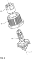
- the present invention describes a connecting element 1 with which two components A, B are connected to each other (see Figures 1 , 12 , 20, 21 ). Within the connection produced, the connecting element 1 maintains a defined distance between the two components A, B. In addition, due to its design, the connecting element 1 is able to compensate for existing tolerances in the alignment of the components A, B to be connected to one another in order to improve the quality, reliability and load-bearing capacity of the connection produced.
- the connecting element 1, 101; 201; 301 enables axial tolerance compensation in the direction of a longitudinal axis L of the hollow screw 10; 110; 210; 310 and lateral tolerance compensation transverse to the longitudinal axis L of the hollow screw 10; 110; 210; 310.
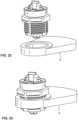
- a first preferred embodiment of the connecting element 1 is shown in a perspective sectional view in Figure 1 It consists of a sleeve-like hollow screw 10 with an external thread 12 and an internal cavity 14.
- the hollow screw 10 is screwed into an opening O of the first component A.
- the thread 12 is configured as a self-tapping and/or self-forming thread. It is also preferred to use other thread configurations that realize a suitable fastening in the opening O of the first component A.
- the self-tapping and/or self-tapping thread creates an anti-rotation effect which holds the hollow screw 10 in the opening O. Even if the hollow screw 10 is adjusted in its axial position by further turning after installation, the self-tapping and/or self-tapping thread continues to ensure a reliable hold of the hollow screw 10 in the opening O of the first component A.
- the banjo bolt 10 has a first opening 18 at a first axial end 16 which is large enough to insert a nut member 40 into the cavity 14 of the banjo bolt 10.
- the nut member 40 which is described in more detail below, is preferably received in the cavity 14 in an approximately coaxial orientation to the longitudinal axis L of the banjo bolt 10.
- a second opening 22 is provided at a second axial end 20 of the hollow screw 10.
- the second opening 22 is smaller in diameter than the first opening 18.
- the second opening 22 is reduced in size by a radial collar 26 that projects radially inwards and on which the nut element 40 is supported by a connecting bolt 60 (see below).
- the hollow screw 10 is in the Figures 3 and 4 shown in more detail in perspective.
- an external drive means 24 in particular a polygon or hexagon, is provided adjacent or next to the second opening 22 of the hollow screw 10.
- the drive means 24 serves to transmit a torque to the hollow screw 10 in order to screw it into the opening O of the first component A and thus fasten it.
- the radial collar 26 preferably has a contact surface 28 for the connecting bolt 60 on an axial outer side.
- the contact surface 28 is preferably designed in a ring shape. It is also preferred to arrange this contact surface 28 in a square shape or consisting of several surface segments in a regular arrangement around the second opening 22 of the hollow screw 10.
- the contact surface 28 also preferably forms a contact surface with the connecting bolt 60, if it is supported or clamped by means of a connecting flange 62 in a force-locking connection with the nut element 40 on the radial collar 26 via the contact surface 28.
- a circumferential embossed rib 30 is preferably provided adjacent to the opening 22 at the first axial end 16.
- the embossed rib 30 also preferably projects beyond the contact surface 28 in the axial direction. It has a round or square circumferential shape.
- the axially protruding embossed rib 30 is preferably pressed or stamped into a connecting flange 62 of the connecting bolt 60 in the force-locking connection between the nut element 40 and the connecting bolt 60.
- this forms a positive connection between the hollow screw 10 and the connecting flange 62 of the connecting bolt 60.
- the positive connection serves to support and ensure the radial position of the nut element 40 and the connecting bolt 60 in relation to the hollow screw 10.
- the positive connection preferably seals the connecting element 1 against media penetrating from the outside, for example by forming a labyrinth seal.
- the hollow screw 10 has a second drive means 32 adjacent to the first axial end 16.
- the drive means 32 is provided according to different preferred embodiments on the axial end face of the first axial end 16 or on the radial outside of the hollow screw 10 or on the radial inside of the cavity 14. Due to its arrangement, the drive means 32 enables accessibility for a tool even when the connecting element 1 is installed and connecting two components. With the aid of a preferred positive connection between the tool and the drive means 32, a torque can be transmitted to the hollow screw 10 in order to change an axial position of the hollow screw 10 in the opening O of the first component A.
- the connecting bolt 60 is according to a first preferred embodiment of the present invention in the Figures 5 and 6 shown in more detail.
- the connecting bolt 60 is adapted to cooperate with the preferred embodiment of the nut element 40 according to the Figures 7 and 8 preferably to form a detachable connection.
- the preferred connecting bolt 60 has a first axial connecting end 64 in order to establish a positive and/or non-positive connection with the nut element 40.
- the cooperating connecting surfaces of the nut element 40 and the first connecting end 64 of the connecting bolt 60 are designed such that the connection between the connecting bolt 60 and the nut element 40 can be released without causing any damage.
- the connecting surfaces of the first connecting end 64 of the connecting bolt 60 are arranged along a shaft 66 of the connecting bolt 60.
- the shaft 66 is arranged in the cavity 14 of the hollow screw 10 and passes through the nut element 40, which is also arranged there.
- the first connection end 64 is preferably limited in the axial direction by the radially extending connection flange 62, which is arranged outside the cavity 14 of the hollow screw 10.
- the first connection end 64 also runs into a drive means 68 in order to rotate the connection bolt 60 via it.
- the drive means 68 is preferably designed as a polygon, a slot, a web, a cross or an Allen key.
- a second axial connection end 70 Adjacent to the connecting flange 62, a second axial connection end 70 is provided on the side of the connecting bolt 60 facing away from the shaft.
- the second axial connection end 70 is adapted to establish a connection, preferably a detachable connection, with the second component B.
- the second connection end 70 it forms a quick-release fastener with an opening O in the second component B.
- a bayonet connection is preferred, so that the second connection end 70 can be inserted into a keyhole S (see Figure 24 ) and locks there by a quarter turn.
- the second connection end 70 is also preferred to design the second connection end 70 as a threaded bolt or threaded shaft in order to fasten it in the opening O of the second component B by means of a nut.
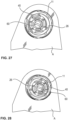
- the second connection end 70 has in the Figure 6 shown preferred embodiment a central centering projection 72 with oppositely arranged and radially projecting Locking wings 74.
- the centering projection 72 comprises two centering planes 73 arranged opposite one another and tapering radially inwardly towards the free end of the centering projection 72. These centering planes 73 support the second connection end 70 running into the opening O of the second component B.
- an orientation web 76 is arranged on the centering projection 72, which indicates the angle of rotation setting of the connecting bolt 60 in relation to the keyhole S.
- a similar marking is preferably also found on the axial end of the first connecting end 64.
- the centering projection 72 is inserted through a central opening and the radially projecting locking wings 74 are inserted through radial recesses of the keyhole S (see Figure 25 ).
- the connecting bolt 60 is then rotated about its longitudinal axis L, preferably via the drive feature 68, until, after a rotation of preferably 90°, at least one locking bar 78, preferably two locking bars arranged opposite one another, engage in the radial recesses of the keyhole S (see Figure 26 ).
- the locking bar 78 is provided on one side with a release ramp 79.
- the locking bar 78 preferably runs along a partial circular arc around the longitudinal axis L of the connecting bolt 60. Accordingly, the release ramp 79 is attached to a (see Figure 6 ) or at both ends of the locking web 78.
- the connecting bolt 60 is rotated such that the release ramp 79 meets a radial edge of a radial recess of the keyhole S. Due to the rotation, the release ramp 79 presses the locking web 78 in the axial direction out of the radial recess, whereby it is released and enables further rotation of the connecting bolt 60.
- the connecting bolt 60 passes through the second opening 22 of the hollow screw 10 and is held in the cavity 14 by the nut element 40.
- the connecting bolt 60 is according to the Figures 5 and 6 detachably connected to the nut element 40, which is in the Figures 7 and 8 according to preferred embodiments.
- the nut element 40 is constructed in a sleeve-like manner with a circumferential wall 42, an interior space 44 enclosed by the wall 42, an inlet opening 46 and an outlet opening 48.
- the circumferential wall 42 has at least two recesses in order to form an intermediate locking arm 50 extending in the axial direction. More preferably, the nut element 40 has two radially inwardly engaging locking arms 50 which are arranged opposite one another.
- the locking arms 50 have a locking projection 52 that projects radially inwards.
- the locking arm 50 with locking projection 52 preferably creates a releasable snap or locking connection with the connecting bolt 60 as soon as the connecting bolt 60 is axially inserted into the nut element 40 arranged in the cavity 14 of the hollow screw 10.
- This preferably pre-fixing connection between the nut element 40 and the connecting bolt 60 ensures a positioning movement of the connected parts in the radial direction within the cavity 14 of the hollow screw 10.
- the outer limit of the radial mobility is determined by the inner diameter of the second opening 22 of the hollow screw 10.
- the locking projection 52 preferably snaps into a recess 80 for pre-positioning the connecting bolt 60 on the nut element 40.
- the locking projection 52 slides on a positioning ramp 82 into or towards the recess 80.
- a guide cam 54 of the nut element 40 preferably engages in a guide groove 84 on the shaft 66, which preferably runs in the axial direction of the connecting bolt 60.
- the inclusion of the guide cam 54 in the guide groove 84 brings about a preferred relative axial guidance between the nut element 40 and connecting bolt 60.
- the nut element 40 and connecting bolt 60 are protected against twisting against each other.
- the positive connection between the guide cam 54 and the guide groove 84 as well as between the locking projection 52 and the recess 80 individually or together as an anti-twisting device between the nut element 40 and the connecting bolt 60.
- the hollow screw 10 is screwed into the opening O in component A. This is preferably done as a pre-positioning step of the connecting element 1 or as the first step in a connection process of the two components A and B.
- the nut element 40 is already pre-assembled with the connecting bolt 60 in the cavity 14 of the hollow screw 10, i.e. not yet firmly connected. This means that the connecting bolt 60 and the nut element 40 are pre-fixed to one another via at least one locking connection (see above). This pre-fixing ensures radial and partially axial mobility of the connecting bolt 60 in the cavity 14.
- the second connection end 70 is then preferably fastened in the opening O of the second component B.
- the second axial connection end 70 and the opening O in the second component B form a quick-lock or a bayonet connection (see below).
- connection of the hollow screw 10 to the first component A and the connecting bolt 60 to the second component B preferably results in the required radial position of the connecting bolt 60 within the second opening 22 of the hollow screw 10. Accordingly, a radial tolerance compensation was carried out, supported by the preferably loose connection between the nut element 40 and the connecting bolt 60. This led to an adjustment of the radial position of the connecting bolt 60 in the connecting element 1 to the alignment of the components A and B to one another.
- the radial position of the connecting bolt 60 is preferably fixed in the hollow screw 10.
- a tool also preferably transmits a torque to the nut element 40 via a drive feature 56 in the circumferential wall 42 of the nut element 40, preferably a recess on the radial outside of the nut element 40.
- the resulting rotation of the nut element 40 on the shaft 66 of the connecting bolt 60 results in the guide cam 54 being guided via an insertion bevel 86 into a fastening position 88 in the shaft 66 of the connecting bolt 60.
- the guide cam 54 is guided via the insertion bevel 86 into the fastening position 88 on the connecting bolt 60.
- the movement of the guide cam 54 leads to the connecting bolt 60 being displaced in the axial direction towards or into the nut element 40, while the nut element 40 is supported on the radial collar 26 in the cavity 14.
- the connecting bolt 60 is clamped via its connecting flange 62 on the radial collar 26 of the hollow screw 10 or are fixed in a certain radial position in relation to the central longitudinal axis L of the hollow screw 10 by friction.
- a sealing element 90 is provided on the connecting flange 62 of the connecting bolt 60.
- the sealing element 90 has a hat-like or pot-like shape with a base 92 and a circumferentially projecting wall 94.
- the opening of the sealing element 90, which results from the shape features, is preferably oriented in the direction of the second connecting end 70 of the connecting bolt 60.
- the sealing element 90 preferably consists of an elastic material, it seals against the component B when a connection is made, as shown in the Figures 10 and 17 is shown.
- the base surface 92 is designed as a circular ring, the diameter of the inner opening of which is determined by the diameter of the shaft 66 of the connecting bolt 60.
- the size of this base surface 92 has the advantage that the sealing element 90 is held between the connecting flange 62 and the adjacent contact surface 28 of the hollow screw 10 in a frictional or force-fitting manner. This leads to a sealing of the connecting element 1 to the outside.
- the hollow screw 10 has the embossed rib 30.
- the ring-shaped, circumferential embossed rib 30 preferably protrudes beyond the contact surface 28 at the second axial end 20.
- the embossed rib 30 deforms the sealing element 90 and thereby preferably forms a type of labyrinth seal.
- the circular ring of the base surface 192 is reduced to a retaining collar that projects radially inwards.
- a side of the connecting flange 62 facing the shaft is available for the frictional connection on the radial collar 26.
- the connecting flange 62 preferably has radial ribs 63 that are embossed into the contact surface 28 and/or the embossed rib 30 in the frictional connection with the nut element 40. In this way, additional positive connections are formed that support the function of the connecting element 1.
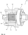
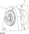
- FIG. 12 A further preferred embodiment of the connecting element 101 is shown in perspective in the Figures 12 and 16 shown.
- Figure 13 shows only three components of the connecting element 101 in a perspective exploded view, while in the Figures 14 and 15 the connecting bolt 160 and the nut element 140 are shown individually.
- connection element 1 As in Figure 1
- the further preferred embodiment of the connecting element 1 shown as an example consists of Figure 12 from only three components.
- the connecting bolt 60; 160 with sealing element 90; 190 is considered to be one component.
- the use of only three components to provide the connecting element 1; 101 results in low manufacturing costs in terms of production, material costs and assembly.
- the installation costs are preferably reduced because the connection is limited to the hollow screw 10; 110 and the second connection end 70; 170 of the connecting bolt 60; 160. This part limitation and the associated advantages apply to all connecting elements 1; 101; 201; 301 described here.
- the shaft 166 of the connecting bolt 160 has an external thread 181 and the nut element 140 has a matching internal thread 149. Accordingly, the nut element 140 and the connecting bolt 160 are connected to one another in a rotational manner.
- the rotation is applied in a known manner via the drive feature 156 on the nut member 140 and/or via the drive feature 168 on the connecting bolt 160.
- the external thread 181 of the connecting bolt 160 has at least one locking rib 183 for thread locking.
- the nut element 140 is screwed onto the external thread 181 of the shaft 166.
- the nut element 140 is only screwed on so far that the internal thread 149 does not yet reach the locking rib 183.
- the nut element 140 can still be positioned axially and together with the connecting bolt 160 radially in the hollow screw 110.
- the nut element 140 is screwed completely onto the external thread 181.
- the connecting flange 162 and the nut element 140 clamp the radial collar 126 between them in a frictional or force-locking manner, as shown in Figure 17
- the selected radial position of the connecting bolt 160 is fixed, as shown in the Figures 27, 28
- the locking rib 183 also preferably prevents the threaded connection between the nut element 140 and the connecting bolt 160 from loosening if no minimum torque is applied to overcome the thread lock.
- the Figures 16 and 17 the installation process of the connecting element 101 already described above. After the connection consisting of the nut element 140 and the connecting bolt 160 has been pre-positioned in the hollow screw 110, the hollow screw 110 is screwed into the opening O of the first component A.
- the movable connection consisting of nut element 140 and connecting bolt 160 is preferably positioned radially so that the second axial connecting end 170 of the connecting bolt 116 is aligned with the preferred keyhole S of the second component B.
- the connecting bolt 160 By preferentially rotating the connecting bolt 160 via the drive feature 168, the second connecting end 170 is secured in the keyhole S.
- a torque is transmitted to the nut element 140 via a suitable form-fit connection with the drive feature 156 on the nut element 140.
- Turning the nut element 140 screws the internal thread 149 further onto the external thread 166 of the connecting bolt 160.
- the screwing ends with an effective frictional connection or clamping of the connecting flange 162 and the nut element 140 on the circumferential radial collar 126 of the hollow screw 110.
- the radial ribs 163 of the connecting flange 162 are also preferably pressed into the embossed rib 130 in order to achieve additional form-fit connection.
- the sealing element 190 already seals against the second component B when the second connection end 170 is connected to the second component B.
- the nut element 140 is equipped with an axially protruding compression limiter 158.
- the compression limiter 158 protrudes in an annular shape in the direction of the connecting flange 162 from the nut element 140.
- the compression limiter 158 is, according to various preferred embodiments, available as a single part (see Figure 18 ) or integrated into the nut element 140 (see Figure 19 ).
- the connecting flange 162 is preferably screwed onto the block with the compression limiter 158.
- This block screw connection limits the strength of the clamping of the radial collar 126 of the hollow screw 110 between the nut element 140 and the connecting flange 162.
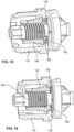
- a further preferred embodiment of the connecting element 201 shows Figure 20 .
- the nut element 240 is not detachably attached to the shaft 266 of the connecting bolt 260.
- the nut element 240 is constructed similarly to a snap ring. Accordingly, an inner diameter of the nut element 240 is smaller than an outer diameter of the shaft 266 of the connecting bolt 260.
- the nut element 240 has an axially continuous gap 243 in the wall 242. This allows the approximately ring-shaped wall 242 to be expanded in diameter, to clamp the nut element 240 onto the shaft 266.
- the frictional connection achieved in this way between the shaft 266 and the nut element 240 ensures the likewise frictional or force-fitting connection between the connecting flange 262 and the nut element 240 on the radial collar 226 of the hollow screw 210.
- the hollow screw 210 is first screwed into the component A (step S1).
- the nut element 240 and the connecting bolt 260 are loosely connected to each other in the cavity 214 of the hollow screw 210.
- step S2 By rotating the connecting bolt 260 via the drive means 268, the second connecting end 270 is fastened in the second component B (step S2).
- the appropriate radial position of the connecting bolt 260 could be set in alignment with the connected components A, B.
- the nut element 240 is displaced as far as possible in the direction of the connecting flange 262 using a suitable tool on the shaft 266 based on its clamping ring-like configuration. Due to the clamping configuration, the nut element 242 maintains the frictional connection with the connecting bolt 260 in the radial position on the radial collar 226 and thereby also preferably fixes the radial position of the nut element 240 and connecting bolt 260 in the cavity 214.
- FIG. 21 A further preferred embodiment of the connecting element 301 is shown in Figure 21 shown.
- the nut element 340 is designed as a non-detachable locking ring structure. Accordingly, the nut element 340 has a circumferential ring 341 with a plurality of locking webs 345 extending therefrom in the axial direction. The locking webs 345 run in the direction of the drive feature 368 and are supported on a locking projection 367 running around the shaft 366.
- the installation of the connecting element 301 is carried out analogously to the installation of the connecting element 201 described above.
- connection method of the first A and the second component B at a defined distance from one another which has already been described above for the various preferred embodiments of the connecting element 1; 101; 201; 301, can be summarized in the following steps.
- a first step S1 the hollow screw 10; 110; 210; 310 of the connecting element 1; 101; 201; 301 is screwed into the first fastening opening O on the first component A.
- the second connection end 70; 170; 270; 370 of the connecting bolt 60; 160; 260; 360 is then fastened in a second fastening opening S of the second component B, whereby radial tolerances in an axial alignment of the hollow screw 10; 110; 210; 310 and the connecting bolt 60; 160; 260; 360 are compensated.
- the nut element 40; 140; 240; 340 and the first connecting end 64; 164; 264; 364 of the connecting bolt 60; 160; 260; 360 are firmly connected to one another so that the connecting bolt 60; 160; 260; 360 is fastened to the hollow screw 10; 110; 210; 310.
- the hollow screw 10; 110; 210; 310 is rotated in the first component A in order to adjust an axial position of the connecting element 1; 101; 201; 301.
- the nut element 40; 140; 240; 340 is loosened within the hollow screw 10; 110; 210; 310, then a radial position of the connecting bolt 60; 160; 260; 360 is changed in comparison to the hollow screw 10; 110; 210; 310 and then the nut element 40; 140; 240; 340 is refastened to the connecting bolt 60; 160; 260; 360.
Landscapes
- Engineering & Computer Science (AREA)
- General Engineering & Computer Science (AREA)
- Mechanical Engineering (AREA)
- Chemical & Material Sciences (AREA)
- Combustion & Propulsion (AREA)
- Transportation (AREA)
- Mutual Connection Of Rods And Tubes (AREA)
Applications Claiming Priority (1)
| Application Number | Priority Date | Filing Date | Title |
|---|---|---|---|
| DE102023103194.5A DE102023103194A1 (de) | 2023-02-09 | 2023-02-09 | Verbindungselement zweier zueinander beabstandeter Bauteile mit Toleranzausgleichsfunktion sowie ein Installationsverfahren dafür |
Publications (3)
| Publication Number | Publication Date |
|---|---|
| EP4414567A1 true EP4414567A1 (fr) | 2024-08-14 |
| EP4414567C0 EP4414567C0 (fr) | 2026-01-28 |
| EP4414567B1 EP4414567B1 (fr) | 2026-01-28 |
Family
ID=89771854
Family Applications (1)
| Application Number | Title | Priority Date | Filing Date |
|---|---|---|---|
| EP24154458.4A Active EP4414567B1 (fr) | 2023-02-09 | 2024-01-29 | Élément de liaison de deux composants espacés l'un par rapport à l'autre présentant une fonction de compensation de tolérance et procédé d'installation associé |
Country Status (4)
| Country | Link |
|---|---|
| US (1) | US20240271645A1 (fr) |
| EP (1) | EP4414567B1 (fr) |
| CN (1) | CN118462695A (fr) |
| DE (1) | DE102023103194A1 (fr) |
Cited By (1)
| Publication number | Priority date | Publication date | Assignee | Title |
|---|---|---|---|---|
| DE102024130178A1 (de) | 2024-10-17 | 2026-04-23 | Böllhoff Verbindungstechnik GmbH | Schnellbefestiger, eine Verbindung zwischen zwei Bauteilen mit dem Schnellbefestiger sowie ein Verbindungs- und ein Herstellungsverfahren dafür |
Citations (9)
| Publication number | Priority date | Publication date | Assignee | Title |
|---|---|---|---|---|
| DE4224575A1 (de) | 1991-08-26 | 1993-03-04 | Ewald Witte Gmbh & Co Kg | Vorrichtung zum verspannenden verbinden von mit abstand zueinanderliegenden bauteilen |
| DE102007002699A1 (de) | 2007-01-18 | 2008-07-24 | Daimler Ag | Befestigungseinrichtung insbesondere für einen Kraftwagen |
| EP2003346A2 (fr) * | 2007-06-11 | 2008-12-17 | Böllhoff Verbindungstechnik GmbH | Dispositif de fixation doté d'une égalisation de tolérance |
| US20150224916A1 (en) * | 2014-02-07 | 2015-08-13 | Dennis WANDELT | Vehicle headlight assembly with self-adjusting fasteners |
| US20170051780A1 (en) | 2015-08-20 | 2017-02-23 | Termax Corporation | Fastener Clip Assembly with Removable Seal |
| US20180328390A1 (en) | 2015-11-13 | 2018-11-15 | A. Raymond Et Cie | Element for positioning a component in space |
| DE102017124470A1 (de) * | 2017-10-19 | 2019-04-25 | Böllhoff Verbindungstechnik GmbH | Toleranzausgleichsanordnung |
| DE102018132192A1 (de) * | 2018-12-13 | 2020-06-18 | Böllhoff Verbindungstechnik GmbH | Hohlzylinderförmiges Basiselement einer Verbindungseinheit |
| EP3612740B1 (fr) * | 2017-05-03 | 2020-10-14 | Böllhoff Verbindungstechnik GmbH | Unité de réglage et procédé de réglage d'un composant |
Family Cites Families (3)
| Publication number | Priority date | Publication date | Assignee | Title |
|---|---|---|---|---|
| DE202005016823U1 (de) * | 2005-10-26 | 2006-02-09 | Böllhoff Verbindungstechnik GmbH | Befestigungseinrichtung mit Toleranzausgleich |
| DE102010000134B4 (de) * | 2010-01-20 | 2023-11-30 | Witte Automotive Gmbh | Abstandsverschraubungselement für Leichtbauformteile |
| DE102021105786A1 (de) * | 2021-03-10 | 2022-09-15 | Böllhoff Verbindungstechnik GmbH | Toleranzausgleichsanordnung |
-
2023
- 2023-02-09 DE DE102023103194.5A patent/DE102023103194A1/de active Pending
-
2024
- 2024-01-29 EP EP24154458.4A patent/EP4414567B1/fr active Active
- 2024-02-06 CN CN202410168218.1A patent/CN118462695A/zh active Pending
- 2024-02-08 US US18/437,063 patent/US20240271645A1/en active Pending
Patent Citations (9)
| Publication number | Priority date | Publication date | Assignee | Title |
|---|---|---|---|---|
| DE4224575A1 (de) | 1991-08-26 | 1993-03-04 | Ewald Witte Gmbh & Co Kg | Vorrichtung zum verspannenden verbinden von mit abstand zueinanderliegenden bauteilen |
| DE102007002699A1 (de) | 2007-01-18 | 2008-07-24 | Daimler Ag | Befestigungseinrichtung insbesondere für einen Kraftwagen |
| EP2003346A2 (fr) * | 2007-06-11 | 2008-12-17 | Böllhoff Verbindungstechnik GmbH | Dispositif de fixation doté d'une égalisation de tolérance |
| US20150224916A1 (en) * | 2014-02-07 | 2015-08-13 | Dennis WANDELT | Vehicle headlight assembly with self-adjusting fasteners |
| US20170051780A1 (en) | 2015-08-20 | 2017-02-23 | Termax Corporation | Fastener Clip Assembly with Removable Seal |
| US20180328390A1 (en) | 2015-11-13 | 2018-11-15 | A. Raymond Et Cie | Element for positioning a component in space |
| EP3612740B1 (fr) * | 2017-05-03 | 2020-10-14 | Böllhoff Verbindungstechnik GmbH | Unité de réglage et procédé de réglage d'un composant |
| DE102017124470A1 (de) * | 2017-10-19 | 2019-04-25 | Böllhoff Verbindungstechnik GmbH | Toleranzausgleichsanordnung |
| DE102018132192A1 (de) * | 2018-12-13 | 2020-06-18 | Böllhoff Verbindungstechnik GmbH | Hohlzylinderförmiges Basiselement einer Verbindungseinheit |
Cited By (1)
| Publication number | Priority date | Publication date | Assignee | Title |
|---|---|---|---|---|
| DE102024130178A1 (de) | 2024-10-17 | 2026-04-23 | Böllhoff Verbindungstechnik GmbH | Schnellbefestiger, eine Verbindung zwischen zwei Bauteilen mit dem Schnellbefestiger sowie ein Verbindungs- und ein Herstellungsverfahren dafür |
Also Published As
| Publication number | Publication date |
|---|---|
| US20240271645A1 (en) | 2024-08-15 |
| CN118462695A (zh) | 2024-08-09 |
| EP4414567C0 (fr) | 2026-01-28 |
| EP4414567B1 (fr) | 2026-01-28 |
| DE102023103194A1 (de) | 2024-08-14 |
Similar Documents
| Publication | Publication Date | Title |
|---|---|---|
| EP2318723B1 (fr) | Agencement de fixation avec compensation des tolerances | |
| EP2217469B1 (fr) | Élément de positionnement | |
| EP2720907B1 (fr) | Dispositif de fixation comprenant un compensateur de tolérance | |
| EP2218924B1 (fr) | Dispositif de fixation destiné à l'agencement sur un rail de montage | |
| DE102007037242B4 (de) | Befestigungseinrichtung mit Toleranzausgleich | |
| EP2532568B1 (fr) | Dispositif de fixation d'un composant, par exemple d'une rambarde, sur une carrosserie de véhicule | |
| EP2082143B1 (fr) | Association composée d'une vis, d'une rondelle et d'une douille, et procédé de production d'une telle combinaison | |
| EP2130722B1 (fr) | Elément d'équilibrage de tolérance | |
| EP3384167B1 (fr) | Douille d'écartement réglable | |
| EP3036443B1 (fr) | Procédé pour assembler des pièces et module correspondant | |
| EP4293241B1 (fr) | Un élément de réglage et un procédé d'installation d'un élément de montage à l'aide de l'élément de réglage | |
| EP3612740B1 (fr) | Unité de réglage et procédé de réglage d'un composant | |
| EP4048908B1 (fr) | Élément de connexion et agencement de connexion | |
| WO2020088878A1 (fr) | Unité de liaison servant à relier deux composants à une distance entre eux | |
| DE102021105786A1 (de) | Toleranzausgleichsanordnung | |
| WO2019110366A1 (fr) | Module de montage pour une lampe de véhicule | |
| EP4414567B1 (fr) | Élément de liaison de deux composants espacés l'un par rapport à l'autre présentant une fonction de compensation de tolérance et procédé d'installation associé | |
| EP4095398B1 (fr) | Dispositif de compensation des tolérances entre deux composants à connecter | |
| EP4411151B1 (fr) | Élément de réglage doté d'un manchon de fixation amortissant et son procédé d'installation et de fabrication | |
| EP3736464B1 (fr) | Entretoise pour un agencement de fixation, agencement de fixation doté d'une telle entretoise ainsi que procédé de fixation d'une pièce de montage sur une pièce de support | |
| EP4495470B1 (fr) | Ecrou de boulon et son procede de fabrication | |
| EP4202235A1 (fr) | Ensemble de fixation | |
| EP4095397B1 (fr) | Dispositif de compensation des tolérances entre deux composants à connecter l'un à l'autre | |
| EP2857700B1 (fr) | Procédé de fixation d'un premier composant sur un deuxième composant d'un véhicule automobile, ainsi que système de fixation d'un premier composant sur un deuxième composant d'un véhicule automobile | |
| WO2026082857A1 (fr) | Attache rapide, liaison entre deux composants avec l'attache rapide et procédé de liaison et son procédé de production |
Legal Events
| Date | Code | Title | Description |
|---|---|---|---|
| PUAI | Public reference made under article 153(3) epc to a published international application that has entered the european phase |
Free format text: ORIGINAL CODE: 0009012 |
|
| STAA | Information on the status of an ep patent application or granted ep patent |
Free format text: STATUS: THE APPLICATION HAS BEEN PUBLISHED |
|
| AK | Designated contracting states |
Kind code of ref document: A1 Designated state(s): AL AT BE BG CH CY CZ DE DK EE ES FI FR GB GR HR HU IE IS IT LI LT LU LV MC ME MK MT NL NO PL PT RO RS SE SI SK SM TR |
|
| STAA | Information on the status of an ep patent application or granted ep patent |
Free format text: STATUS: REQUEST FOR EXAMINATION WAS MADE |
|
| 17P | Request for examination filed |
Effective date: 20241209 |
|
| GRAP | Despatch of communication of intention to grant a patent |
Free format text: ORIGINAL CODE: EPIDOSNIGR1 |
|
| STAA | Information on the status of an ep patent application or granted ep patent |
Free format text: STATUS: GRANT OF PATENT IS INTENDED |
|
| INTG | Intention to grant announced |
Effective date: 20250919 |
|
| GRAS | Grant fee paid |
Free format text: ORIGINAL CODE: EPIDOSNIGR3 |
|
| GRAA | (expected) grant |
Free format text: ORIGINAL CODE: 0009210 |
|
| STAA | Information on the status of an ep patent application or granted ep patent |
Free format text: STATUS: THE PATENT HAS BEEN GRANTED |
|
| AK | Designated contracting states |
Kind code of ref document: B1 Designated state(s): AL AT BE BG CH CY CZ DE DK EE ES FI FR GB GR HR HU IE IS IT LI LT LU LV MC ME MK MT NL NO PL PT RO RS SE SI SK SM TR |
|
| REG | Reference to a national code |
Ref country code: CH Ref legal event code: F10 Free format text: ST27 STATUS EVENT CODE: U-0-0-F10-F00 (AS PROVIDED BY THE NATIONAL OFFICE) Effective date: 20260128 Ref country code: GB Ref legal event code: FG4D Free format text: NOT ENGLISH |
|
| REG | Reference to a national code |
Ref country code: DE Ref legal event code: R096 Ref document number: 502024000653 Country of ref document: DE |
|
| REG | Reference to a national code |
Ref country code: IE Ref legal event code: FG4D Free format text: LANGUAGE OF EP DOCUMENT: GERMAN |
|
| U01 | Request for unitary effect filed |
Effective date: 20260224 |
|
| U07 | Unitary effect registered |
Designated state(s): AT BE BG DE DK EE FI FR IT LT LU LV MT NL PT RO SE SI Effective date: 20260302 |
|
| PGFP | Annual fee paid to national office [announced via postgrant information from national office to epo] |
Ref country code: AT Payment date: 20260301 Year of fee payment: 3 |