EP4414611A1 - Ensemble comprenant un système de chauffage à la biomasse et un dispositif d'absorption acoustique - Google Patents
Ensemble comprenant un système de chauffage à la biomasse et un dispositif d'absorption acoustique Download PDFInfo
- Publication number
- EP4414611A1 EP4414611A1 EP24156098.6A EP24156098A EP4414611A1 EP 4414611 A1 EP4414611 A1 EP 4414611A1 EP 24156098 A EP24156098 A EP 24156098A EP 4414611 A1 EP4414611 A1 EP 4414611A1
- Authority
- EP
- European Patent Office
- Prior art keywords
- wall
- sound
- assembly
- casing
- gap
- Prior art date
- Legal status (The legal status is an assumption and is not a legal conclusion. Google has not performed a legal analysis and makes no representation as to the accuracy of the status listed.)
- Pending
Links
- 238000010438 heat treatment Methods 0.000 title claims abstract description 60
- 239000002028 Biomass Substances 0.000 title claims abstract description 50
- 238000009423 ventilation Methods 0.000 claims description 8
- 239000011358 absorbing material Substances 0.000 claims description 5
- 238000007789 sealing Methods 0.000 claims description 4
- 241000886569 Cyprogenia stegaria Species 0.000 claims description 3
- 238000005273 aeration Methods 0.000 claims description 3
- 239000012530 fluid Substances 0.000 claims description 3
- 238000013016 damping Methods 0.000 description 10
- 230000007246 mechanism Effects 0.000 description 6
- 238000002485 combustion reaction Methods 0.000 description 4
- 239000000463 material Substances 0.000 description 4
- 239000011148 porous material Substances 0.000 description 4
- 230000003466 anti-cipated effect Effects 0.000 description 2
- 230000000694 effects Effects 0.000 description 2
- 239000008188 pellet Substances 0.000 description 2
- 241001272720 Medialuna californiensis Species 0.000 description 1
- 230000007423 decrease Effects 0.000 description 1
- 238000009429 electrical wiring Methods 0.000 description 1
- 239000011521 glass Substances 0.000 description 1
- 230000001788 irregular Effects 0.000 description 1
- 239000002184 metal Substances 0.000 description 1
- 239000011490 mineral wool Substances 0.000 description 1
- 229920003023 plastic Polymers 0.000 description 1
- 239000004033 plastic Substances 0.000 description 1
- 229920000728 polyester Polymers 0.000 description 1
- 229920002635 polyurethane Polymers 0.000 description 1
- 239000004814 polyurethane Substances 0.000 description 1
- 239000002023 wood Substances 0.000 description 1
Images




Classifications
-
- F—MECHANICAL ENGINEERING; LIGHTING; HEATING; WEAPONS; BLASTING
- F24—HEATING; RANGES; VENTILATING
- F24B—DOMESTIC STOVES OR RANGES FOR SOLID FUELS; IMPLEMENTS FOR USE IN CONNECTION WITH STOVES OR RANGES
- F24B13/00—Details solely applicable to stoves or ranges burning solid fuels
- F24B13/002—Surrounds
-
- F—MECHANICAL ENGINEERING; LIGHTING; HEATING; WEAPONS; BLASTING
- F24—HEATING; RANGES; VENTILATING
- F24B—DOMESTIC STOVES OR RANGES FOR SOLID FUELS; IMPLEMENTS FOR USE IN CONNECTION WITH STOVES OR RANGES
- F24B1/00—Stoves or ranges
- F24B1/18—Stoves with open fires, e.g. fireplaces
- F24B1/181—Free-standing fireplaces, e.g. for mobile homes ; Fireplaces convertible into stoves
-
- F—MECHANICAL ENGINEERING; LIGHTING; HEATING; WEAPONS; BLASTING
- F24—HEATING; RANGES; VENTILATING
- F24B—DOMESTIC STOVES OR RANGES FOR SOLID FUELS; IMPLEMENTS FOR USE IN CONNECTION WITH STOVES OR RANGES
- F24B1/00—Stoves or ranges
- F24B1/18—Stoves with open fires, e.g. fireplaces
- F24B1/185—Stoves with open fires, e.g. fireplaces with air-handling means, heat exchange means, or additional provisions for convection heating ; Controlling combustion
-
- F—MECHANICAL ENGINEERING; LIGHTING; HEATING; WEAPONS; BLASTING
- F24—HEATING; RANGES; VENTILATING
- F24B—DOMESTIC STOVES OR RANGES FOR SOLID FUELS; IMPLEMENTS FOR USE IN CONNECTION WITH STOVES OR RANGES
- F24B1/00—Stoves or ranges
- F24B1/18—Stoves with open fires, e.g. fireplaces
- F24B1/191—Component parts; Accessories
- F24B1/195—Fireboxes; Frames; Hoods; Heat reflectors
-
- F—MECHANICAL ENGINEERING; LIGHTING; HEATING; WEAPONS; BLASTING
- F24—HEATING; RANGES; VENTILATING
- F24B—DOMESTIC STOVES OR RANGES FOR SOLID FUELS; IMPLEMENTS FOR USE IN CONNECTION WITH STOVES OR RANGES
- F24B7/00—Stoves, ranges or flue-gas ducts, with additional provisions for convection heating
Definitions
- the invention is developed in the technical field of biomass heating systems.
- the invention concerns an assembly of a biomass heating system, for example a stove, a thermostove, a boiler or a fireplace, and a sound-absorbing device.
- Biomass heating systems are known in the art.
- the biomass heating systems comprise a casing, inside which there is a combustion chamber in which a flame is produced.
- the heat generated by the flame is diffused to an external environment, to be heated, through one or more fans.
- openings are provided in the casing of the biomass heating system for the air to pass.
- the technical task underlying the present invention is to reduce the noise generated by the biomass heating system reaching the external environment, with a specific sound-absorbing device for biomass heating systems.
- the aim of the present invention is to provide an assembly of a biomass heating system and a sound-absorbing device, which overcomes the drawbacks of the aforementioned prior art.
- the defined technical task and the specified aims are substantially achieved by an assembly of a biomass heating system and a sound-absorbing device comprising the technical characteristics set forth in one or more of the appended claims.
- the assembly comprises a sound-absorbing device suitable for the biomass heating systems that optimally dampens noises generated by such biomass heating systems to which it is applied.
- the device has an inner wall turned towards the biomass heating system.
- the inner wall has openings, which allow acoustic waves to enter a gap of the device.
- the gap is closed on the opposite side by an impervious outer wall. The noise is therefore dampened inside the gap.
- the present invention relates to an assembly 1 of a biomass heating system 2 and a sound-absorbing device 3.
- Biomass heating system refers to a device configured to produce heat starting from the combustion of biomasses, such as pellets or wood chips.
- the biomass heating system 2 is one of the following: a stove, a thermostove, a boiler or a fireplace.
- the invention will be schematically described and illustrated with reference to a preferred embodiment wherein the biomass heating system is a pellet stove.
- the biomass heating system 2 and the sound-absorbing device 3 of the assembly 1 can be connected to each other, or they can be separate bodies without mechanical connections to each other, to be positioned in an appropriate way during operation for a correct noise reduction.
- the biomass heating system 2 comprises in a known manner a casing 21 and a combustion chamber inside the casing 21, not illustrated.
- the casing 21 of the biomass heating system 2 has at least one front wall 21a and a rear wall 21b, opposite the front wall 21a.
- the front wall 21a is a wall generally intended to be turned towards the centre of a room of a building, while the rear wall 21b is intended to be turned towards a wall of the room proximal to the heating system 2.
- one or more elements of connection to utilities of a building are usually arranged at the rear wall 21b of the heating system 2.
- the biomass heating system 2 comprises a noise source 24a, 24b, for example one or more fans 24a, 24b inside the casing 21.
- the fan is configured to diffuse heat generated inside the combustion chamber outside the biomass heating system 2.
- the rear wall 21b has a plurality of rear openings 23, configured to allow aeration of the biomass heating system 2.
- the rear openings 23 are spaced from the noise source 24a, 24b in an exit direction, which substantially represents the direction followed by the air to exit the casing 21.
- the heating system 2 may comprise multiple noise sources 24a, 24b, e.g. multiple fans, and various rear openings 23 specific to the distinct noise sources 24a, 24b.
- the front wall 21a is usually a continuous wall, devoid of openings.
- a noise source 24a, 24b is given by a first fan 24a, placed in a compartment of the casing 21 delimited at least on one side by the rear wall 21b. It can be observed that, while it might appear from the figures that the compartment substantially occupies the entire casing 21, it is provided that the casing 21 also contains various other inner components or compartments known to the persons skilled in the art and omitted for sake of simplicity.
- the rear openings 23 comprise a plurality of slots 23a distributed on the rear wall 21b and shaped to put the compartment of the casing in fluid communication with the outside.
- the first fan 24a and the slots 23a are therefore dedicated to delivering the heat of the heating system 2 in the room where the heating system 2 is located.
- the slots 23a also represent a passage for unwanted noise of the first fan 24a.
- the heating system 2 is provided for connection with one or more ventilation ducts of the building, configured to convey hot air to other rooms of the building.
- These ventilation ducts can be arranged at least in part inside said proximal wall of the room.
- the rear openings 23 comprise at least one mouth 23b, preferably a plurality of mouths 23b, each configured for connection with at least one ventilation duct external to the casing 21.
- the noise source 24a, 24b comprises at least one second fan 24b, preferably a plurality of second fans 24b, each housed in a respective fan shell in fluid communication with a respective mouth 23b.
- the fan shell, at least on an exhaust side of the second fan 24b, is sealed with respect to the compartment of the casing 21 including the first fan 24a.
- two mouths 23b are provided for connection to respective ventilation ducts, in addition to a further mouth 25 that does not communicate with noise sources 24a, 24b, and can be dedicated for example to electrical wirings.
- mouths 23b and second fans 24b may not be provided, but only a first fan 24a and the slots 23a, or yet no first fan 24a, but only second fans 24b, which may be in any number.
- the sound-absorbing device 3 has an inner wall 33, configured to be turned towards the noise source 24a, 24b in such a way as to be hit by its noise, and an outer wall 34, opposite the inner wall 33. It is worth noting that the inner wall 33 has a sound-absorbing function, which will be described in detail below. Furthermore, the outer wall 34 is impervious, with a sound-insulating function.
- the sound-absorbing device 3 is arranged transversely to the exit direction, at least for a main portion thereof, preferably perpendicularly to the exit direction.
- the sound-absorbing device 3 can be placed substantially vertically, and/or substantially in parallel to the rear wall 21b. Thanks to this arrangement, the sound-absorbing device can be hit frontally, as well as by the air flow, also by the sound waves, and therefore its damping effect is maximum.
- each sound-absorbing device 3 it is possible that it is arranged externally to the casing 21, with the inner wall 33 of the device 3 facing the rear wall 21b of the casing 21.
- a sound-absorbing device 3 may be external to the casing 21 and placed in front of one or more of the slots 23a and at least one of the mouths 23b.
- distinct sound-absorbing devices 3, for example three in number, are in front of the assembly of the slots 23a and distinct mouths 23b.
- the device 3 is flat.
- the system comprises a flat device 3.
- the devices 3 with a flat shape are spaced apart with respect to the biomass heating system 2. It is worth noting that the devices 3 of the embodiments shown in figures 7g and 7h can also be spaced from the biomass heating system 2.
- the system comprises two devices 3.
- each device 3 has an end 32 connected to the casing 21 of the biomass heating system 2.
- the sound-absorbing device 3 has a through channel, not visible in the figures, between the inner wall 33 and the outer wall 34. Inside the through channel, a tube 50, a cable or a device for controlling the biomass heating system 2 can be inserted.
- the tube 50, the cable or the control device have a connection end with which they are connected to the biomass heating system 2.
- the device 3 comprises a gap 35, comprised between the inner wall 33 and the outer wall 34.
- the gap 35 has a gap depth 36 between the inner wall 33 and the outer wall 34.
- the gap depth 36 is constant between the two ends 32.
- the central portion 30a and the arms 30b in the embodiments in which they are provided, have the same gap depth 36.
- the gap depth is comprised between 10 and 40 mm.
- the minimum depth 36a can be identified at the central portion 30a, while the maximum depth 36b can be identified at arms 30b.
- the minimum gap depth 36a may be constant along the central portion 30a.
- the maximum gap depth 36b may be constant along the arms 30b.
- the minimum gap depth 36a can be identified at the ends 32.
- the maximum depth 36b can be identified at the central portion 30a. In this embodiment, the maximum depth can be detected at a centre of symmetry C of the central portion 30a.
- the gap depth 36 progressively decreases from the centre C of the central portion 30a up to the ends 32.
- the gap depth 36 is substantially constant between the two ends 32.
- the inner wall 33 has ridges 33a and depressions 33b.
- the ridges 33a and the depressions 33b may be irregular.
- the gap depth 36 at each ridge 33a is variable, i.e. the ridges 33a have gap depth 36 different from one another.
- a distance L between two consecutive ridges 33a is variable.
- the ridges 33a and the depressions 33b have the same gap depth 36 and the same distance L between two consecutive ridges 33a.
- the distance L is comprised between 5 mm and 5 cm.
- the ridges 33a and depressions are corrugated.
- the ridges 33a and the depressions 33b have a plurality of edges and segments.
- the rear wall 34 of the device 3 may also have ridges and depressions.
- the gap depth 36 may be constant despite the ridges and depressions.
- the inner wall 33 has a sound-absorbing function.
- a first noise damping mechanism is due to the vibration of the inner wall 33.
- the frequency range that is damped by this first mechanism depends, for example, on a material of the inner wall 33 and a thickness of the inner wall 33.
- the inner wall 33 has a plurality of through openings 38 configured to be turned towards the noise source 24a, 24b.
- a second noise damping mechanism is given by the acoustic resonance of the through openings 38 on the wall 33 with the gap 35.
- the openings and the gap 35 form an acoustic resonator that guarantees sound dissipation in a specific range of frequencies, preferably in one or more frequency bands in the range between 500 and 3000 Hz. In detail, this range varies with the variation of parameters such as a thickness of the inner wall 33, the gap depth, a dimension and a shape of the through openings 38.
- the inner wall 33 has pores, not shown in the figures.
- the porosity of the inner wall is for example less than 5%, preferably less than 1%. These pores have a diameter comprised between 0.01 and 3 mm, preferably between 0.1 and 1 mm. It should be noted that the pores also contribute to damping sounds, in particular with regard to the second damping mechanism.
- the parameters affecting damping comprise the porosity of the inner wall 33, a dimension and a shape of the pores.
- the through openings 38 may be slots, or have other shapes.
- the inner wall 33 has ridges 33a and depressions 33b, it is possible to increase the amplitude of a frequency range of the noises that are damped by the sound-absorbing device 3, improving the damping of noises to the outside. In fact, it is possible to obtain local variations of the frequency that is damped at the inner wall 33.
- the device 3 is configured to dampen 5 dB noises with a frequency comprised between 500 and 1000 Hz.
- the device 3 is configured to dampen 4 dB noises with a frequency comprised between 300 and 1500 Hz.
- the gap 35 of the device 3 is empty, as shown in figure 8b .
- the gap 35 of the device 3c is filled at least in part with a sound-absorbing material 4, as shown in figure 8c .
- the sound-absorbing material 4 may totally fill the gap 35 or leave some areas empty.
- such sound-absorbing material 4 is, for example, polyester, polyurethane or rock wool.
- the gap 35 defines an inner volume 37 of the device 3.
- the device 3 comprises, inside the gap 35, at least one dividing element 5, configured to divide the inner volume 37 into several gap portions.
- this dividing element 5 has a height equal to a vertical height H of the sound-absorbing device 3.
- the dividing element 5 forms a mesh, not shown in the figures, composed of mesh elements of different shapes, for example square or hexagonal.
- the device 3 comprises a plurality of dividing elements 5, configured to divide the inner volume 37 into a plurality of gap portions.
- the dividing elements 5 can be distributed in various ways within the gap.
- Each dividing element 5 may have a height equal to the vertical height H of the sound-absorbing device 3, or even a lower height.
- the dividing element 5 further contributes to damping the noises coming from the source.
- the dividing element 5 also performs a structural function, improving the mechanical properties of the sound-absorbing device 3.
- At least one of the gap portions created by at least one dividing element 5 is filled with sound-absorbing material 4.
- the two ends 32 of the sound-absorbing device 3 are connected to the casing 21 of the biomass heating system 2.
- the two ends 32 are connected with a respective sealing element 6, for example gasket elements.
- each sealing element 6 extends along the vertical height H of the sound-absorbing device 3, as shown in figure 1 .
- the noises coming from the noise source 24a, 24b are channelled between the casing 21 and the inner wall 33, since the sealing elements 6 prevent their exit at the ends 32.
- the noises are channelled towards an upper opening S, between the inner wall 33 and the casing 21, which still allows the aeration thereof. This improves noise dissipation.
- the sound waves are channelled towards the upper opening S, they travel a longer path before escaping into the external environment and, during this path, they are more damped by the inner wall 33 thanks to the first and second damping mechanisms, described above.
- the inner wall 33 is spaced from the casing 21 of the biomass heating system 2 by a distance comprised between 5 and 100 mm, preferably between 10 and 30 mm.
- the inner wall is spaced from the casing 21 both at the arms 30b and at the central portion 30a.
- the inner wall 33 is spaced from the casing at the central portion 30a.
- the inner wall 33 can be made of metal, plastic or glass, for example. Furthermore, the inner wall 33 can be made with a combination of such materials or of other materials deemed suitable by the person skilled in the art. In particular, the materials are chosen from those that withstand temperatures comprised between 90 and 200 °C, preferably between 120 and 150 °C.
- the inner wall 33 and/or the outer wall 34 may have a thickness comprised between 0.1 and 20 mm.
- the sound-absorbing device 3 can be built according to different embodiments.
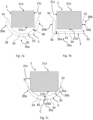
- each sound-absorbing device 3 is facing on at least three walls of the casing 21: the rear wall 21b and at least one pair of side walls 21c, which connect the front wall 21a with the rear wall 21b.
- the rear wall 21b, the at least one pair of side walls 21c and preferably the front wall 21a are joined by edges. In a further embodiment, the rear wall 21b, the at least one pair of side walls 21c and preferably the front wall 21a identify distinct portions of the same arched wall that defines the casing 21.
- the inner wall 33 of the sound-absorbing device 3 is turned towards the rear wall 21b of the casing 21.
- the sound-absorbing devices 3 can be turned towards the at least one pair of side walls 21c. Even in this embodiment, the devices 3 allow to at least partially surround the casing 21.
- each sound-absorbing device 3 is facing only on the rear wall 21b of the casing 21. Furthermore, in the embodiment of figure 7l , each device 3 is connected to the rear wall 21b at a respective end 32.
- the casing 21 of the biomass heating system 2 always has at least one front wall 21a and a rear wall 21b, opposite the front wall 21a.
- the inner wall 33 of the device 3 acts at least in part as the rear wall 21b of the biomass heating system 2.
- the device 3 is an integral part of the casing 21.
- the inner wall 33 of the device 3 acts as the rear wall 2b of the biomass heating system 2.
- at least one device 3 is an integral part of the casing 21.
- the noise coming from the noise source 24a, 24b is damped by the inner wall 33 as soon as it escapes from the casing 21.
- the noise is channelled inside the gap 35.
- the noise sound waves are more damped within the gap 35 through the second damping mechanism. It should also be noted that the noise 35 is confined within the gap 35 since the outer wall 34 is impervious.
Landscapes
- Engineering & Computer Science (AREA)
- Chemical & Material Sciences (AREA)
- Combustion & Propulsion (AREA)
- Mechanical Engineering (AREA)
- General Engineering & Computer Science (AREA)
- Soundproofing, Sound Blocking, And Sound Damping (AREA)
- Exhaust Silencers (AREA)
Applications Claiming Priority (1)
| Application Number | Priority Date | Filing Date | Title |
|---|---|---|---|
| IT102023000002286A IT202300002286A1 (it) | 2023-02-10 | 2023-02-10 | Dispositivo per la riduzione del rumore per sistemi di riscaldamento a biomassa |
Publications (1)
| Publication Number | Publication Date |
|---|---|
| EP4414611A1 true EP4414611A1 (fr) | 2024-08-14 |
Family
ID=86272277
Family Applications (1)
| Application Number | Title | Priority Date | Filing Date |
|---|---|---|---|
| EP24156098.6A Pending EP4414611A1 (fr) | 2023-02-10 | 2024-02-06 | Ensemble comprenant un système de chauffage à la biomasse et un dispositif d'absorption acoustique |
Country Status (2)
| Country | Link |
|---|---|
| EP (1) | EP4414611A1 (fr) |
| IT (1) | IT202300002286A1 (fr) |
Citations (11)
| Publication number | Priority date | Publication date | Assignee | Title |
|---|---|---|---|---|
| JPS4969714U (fr) * | 1972-09-30 | 1974-06-18 | ||
| SE406122B (sv) * | 1975-06-12 | 1979-01-22 | Impuls Innovation Ab | Oppen spis |
| US4862993A (en) * | 1988-09-30 | 1989-09-05 | Rieger Heinz H | Fireplace flue ambient noise reducing device |
| US5983888A (en) * | 1999-04-07 | 1999-11-16 | Whirlpool Corporation | Low noise cooker hood |
| EP1505348A2 (fr) * | 2003-08-08 | 2005-02-09 | Gruppo Piazzetta S.p.A. | Four ou cheminée avec un système de circulation d'air forcée |
| WO2006101403A1 (fr) * | 2005-03-23 | 2006-09-28 | Deamp As | Absorbant acoustique |
| US20170061949A1 (en) * | 2014-05-02 | 2017-03-02 | Ashmere Holdings Pty Ltd | Acoustic Absorption and Methods of Manufacture |
| CN108361740A (zh) * | 2018-01-30 | 2018-08-03 | 浙江中力工具制造有限公司 | 一种生物质取暖炉 |
| US20190212011A1 (en) * | 2018-01-09 | 2019-07-11 | Hni Technologies Inc. | Open hearth fireplace systems and methods |
| EP3158268B1 (fr) * | 2015-06-24 | 2020-05-06 | Invicta Group | Poêle à combustible solide et module d'alimentation d'un tel poêle |
| JP7157974B1 (ja) * | 2021-08-06 | 2022-10-21 | ピクシーダストテクノロジーズ株式会社 | 吸音部材、吸音パネル及び吸音壁 |
-
2023
- 2023-02-10 IT IT102023000002286A patent/IT202300002286A1/it unknown
-
2024
- 2024-02-06 EP EP24156098.6A patent/EP4414611A1/fr active Pending
Patent Citations (11)
| Publication number | Priority date | Publication date | Assignee | Title |
|---|---|---|---|---|
| JPS4969714U (fr) * | 1972-09-30 | 1974-06-18 | ||
| SE406122B (sv) * | 1975-06-12 | 1979-01-22 | Impuls Innovation Ab | Oppen spis |
| US4862993A (en) * | 1988-09-30 | 1989-09-05 | Rieger Heinz H | Fireplace flue ambient noise reducing device |
| US5983888A (en) * | 1999-04-07 | 1999-11-16 | Whirlpool Corporation | Low noise cooker hood |
| EP1505348A2 (fr) * | 2003-08-08 | 2005-02-09 | Gruppo Piazzetta S.p.A. | Four ou cheminée avec un système de circulation d'air forcée |
| WO2006101403A1 (fr) * | 2005-03-23 | 2006-09-28 | Deamp As | Absorbant acoustique |
| US20170061949A1 (en) * | 2014-05-02 | 2017-03-02 | Ashmere Holdings Pty Ltd | Acoustic Absorption and Methods of Manufacture |
| EP3158268B1 (fr) * | 2015-06-24 | 2020-05-06 | Invicta Group | Poêle à combustible solide et module d'alimentation d'un tel poêle |
| US20190212011A1 (en) * | 2018-01-09 | 2019-07-11 | Hni Technologies Inc. | Open hearth fireplace systems and methods |
| CN108361740A (zh) * | 2018-01-30 | 2018-08-03 | 浙江中力工具制造有限公司 | 一种生物质取暖炉 |
| JP7157974B1 (ja) * | 2021-08-06 | 2022-10-21 | ピクシーダストテクノロジーズ株式会社 | 吸音部材、吸音パネル及び吸音壁 |
Also Published As
| Publication number | Publication date |
|---|---|
| IT202300002286A1 (it) | 2024-08-10 |
Similar Documents
| Publication | Publication Date | Title |
|---|---|---|
| US10928096B2 (en) | Environmental control unit including noise reduction features | |
| US6145616A (en) | Acoustic chamber | |
| KR101016601B1 (ko) | 음파의 공명과 팽창 현상을 이용한 환기용 소음기 | |
| US20200224898A1 (en) | Flow generation unit, air treatment plant comprising said flow generation unit and use of the latter for air treatment | |
| JP4410698B2 (ja) | 電子機器収容箱 | |
| CN113160785B (zh) | 用于降低空气传声和固体传声的设备 | |
| US20210048238A1 (en) | Housing for electric apparatus, refrigeration cycle apparatus, and electric apparatus | |
| WO2015079289A1 (fr) | Panneau d'absorption sonore | |
| EP0265000A1 (fr) | Dispositif de ventilation silencieux, notamment pour une ouverture de ventilation dans un mur ou une cloison | |
| KR20100134274A (ko) | 음파의 흡음과 공명에 의하여 감음이 일어나는 공조용 흡음공명형 덕트소음기 | |
| JP2010164241A (ja) | 住宅換気システム | |
| JP4624871B2 (ja) | 換気口用消音装置 | |
| JP2008144996A (ja) | 消音装置 | |
| JP7558305B2 (ja) | 消音装置 | |
| RU2178124C1 (ru) | Глушитель шума | |
| RU2182688C1 (ru) | Звукопоглощающий элемент | |
| KR102101173B1 (ko) | 소음저감장치 | |
| JP4975316B2 (ja) | ダクト部品及びダクト構造 | |
| EP4182610A1 (fr) | Panneau de réduction de bruit pour un appareil de ventilateur axial | |
| JP7553396B2 (ja) | 減音装置及び減音システム | |
| JP4948157B2 (ja) | 消音装置 | |
| JPH02122156A (ja) | 給湯器の排気構造 | |
| RU2831265C1 (ru) | Вентиляционный шумоглушитель | |
| RU2715351C1 (ru) | Звукоизолированный воздуховод | |
| JPS632748Y2 (fr) |
Legal Events
| Date | Code | Title | Description |
|---|---|---|---|
| PUAI | Public reference made under article 153(3) epc to a published international application that has entered the european phase |
Free format text: ORIGINAL CODE: 0009012 |
|
| STAA | Information on the status of an ep patent application or granted ep patent |
Free format text: STATUS: THE APPLICATION HAS BEEN PUBLISHED |
|
| AK | Designated contracting states |
Kind code of ref document: A1 Designated state(s): AL AT BE BG CH CY CZ DE DK EE ES FI FR GB GR HR HU IE IS IT LI LT LU LV MC ME MK MT NL NO PL PT RO RS SE SI SK SM TR |
|
| STAA | Information on the status of an ep patent application or granted ep patent |
Free format text: STATUS: REQUEST FOR EXAMINATION WAS MADE |
|
| 17P | Request for examination filed |
Effective date: 20250211 |