EP4414754A1 - Capteur optique - Google Patents
Capteur optique Download PDFInfo
- Publication number
- EP4414754A1 EP4414754A1 EP23155484.1A EP23155484A EP4414754A1 EP 4414754 A1 EP4414754 A1 EP 4414754A1 EP 23155484 A EP23155484 A EP 23155484A EP 4414754 A1 EP4414754 A1 EP 4414754A1
- Authority
- EP
- European Patent Office
- Prior art keywords
- optical sensor
- receiver
- signal
- transmitter
- signal sections
- Prior art date
- Legal status (The legal status is an assumption and is not a legal conclusion. Google has not performed a legal analysis and makes no representation as to the accuracy of the status listed.)
- Pending
Links
Images




Classifications
-
- G—PHYSICS
- G01—MEASURING; TESTING
- G01V—GEOPHYSICS; GRAVITATIONAL MEASUREMENTS; DETECTING MASSES OR OBJECTS; TAGS
- G01V8/00—Prospecting or detecting by optical means
- G01V8/10—Detecting, e.g. by using light barriers
- G01V8/12—Detecting, e.g. by using light barriers using one transmitter and one receiver
-
- G—PHYSICS
- G01—MEASURING; TESTING
- G01V—GEOPHYSICS; GRAVITATIONAL MEASUREMENTS; DETECTING MASSES OR OBJECTS; TAGS
- G01V8/00—Prospecting or detecting by optical means
- G01V8/10—Detecting, e.g. by using light barriers
- G01V8/12—Detecting, e.g. by using light barriers using one transmitter and one receiver
- G01V8/14—Detecting, e.g. by using light barriers using one transmitter and one receiver using reflectors
-
- G—PHYSICS
- G01—MEASURING; TESTING
- G01V—GEOPHYSICS; GRAVITATIONAL MEASUREMENTS; DETECTING MASSES OR OBJECTS; TAGS
- G01V8/00—Prospecting or detecting by optical means
- G01V8/10—Detecting, e.g. by using light barriers
- G01V8/20—Detecting, e.g. by using light barriers using multiple transmitters or receivers
-
- G—PHYSICS
- G01—MEASURING; TESTING
- G01V—GEOPHYSICS; GRAVITATIONAL MEASUREMENTS; DETECTING MASSES OR OBJECTS; TAGS
- G01V8/00—Prospecting or detecting by optical means
- G01V8/10—Detecting, e.g. by using light barriers
- G01V8/20—Detecting, e.g. by using light barriers using multiple transmitters or receivers
- G01V8/22—Detecting, e.g. by using light barriers using multiple transmitters or receivers using reflectors
Definitions
- the invention relates to an optical sensor.
- the optical sensor is used in particular to detect objects in a monitoring area.
- the optical sensor comprises at least one transmitter that emits light rays and one receiver that receives light rays.
- the optical sensor also comprises an evaluation unit in which an object detection signal is generated depending on the received signals from the receiver.
- the optical sensor works according to the light barrier principle, so that object detection occurs by registering an interruption in the beam path of the light rays that pass through the monitoring area.
- the optical sensor has only one transmitter or receiver, it is designed as a light barrier or reflective light barrier. If the optical sensor has several pairs of transmitters and receivers, it is designed as a light curtain or reflective light curtain.
- a general problem with such optical sensors is that external light influences, particularly stray light radiated into the optical sensor by stray light sources, can lead to malfunctions in the optical sensor. Stray light irradiation can, for example, simulate a clear monitoring area even though an object is in the monitoring area.
- the transmitter of the optical sensor emits light beams in the form of coded light pulses. It is also known that the light beams can be modulated with a modulation frequency.
- the invention is based on the object of providing an optical sensor with further improved resistance to stray light.
- the invention relates to a method for operating an optical sensor with at least one transmitter emitting light beams, at least one receiver receiving light beams and an evaluation unit in which an object detection signal is generated depending on the received signals from the receiver.
- the light beams are modulated with a sequence of signal sections.
- Corresponding signal sections are stored on the receiving side.
- the evaluation unit the received signal from the receiver is correlated with the signal sections stored on the receiving side and, depending on a correlation result obtained in this way, it is assessed whether the light beams emitted by the transmitter are guided to the receiver via a measuring path or not.
- the invention also relates to a corresponding method.
- the basic idea of the invention is therefore to detect whether light rays from the transmitter or a transmitter reach the associated receiver via a measuring path, not only the presence of the light rays or light pulses of the light beams are checked at the receiver. Rather, signal sections are impressed on the light beams in the form of modulations.
- the received signals of the receiver are correlated with signal sections stored in the evaluation unit that correspond to the signal sections of the light beams in order to assess whether the light beams from the transmitter have been guided over the measuring path to the receiver.
- the correlation result can be used to safely and reliably assess whether the received signal was generated by the light beams from the transmitter or was caused by interference light. This significantly increases the interference light resistance of the object detection carried out with the optical sensor.
- the transmitter and the receiver form a light barrier arrangement.
- the optical sensor has several transmitter-receiver pairs, the optical sensor forms a light curtain.
- the object is detected according to the light barrier principle.
- the transmitter and receiver of the or each transmitter-receiver pair are located at opposite edges of a monitoring area. If the monitoring area is clear, the light beams of the transmitter forming the measuring sections of each transmitter-receiver pair hit the assigned receiver, which is registered in the evaluation unit using the correlation result. If an object intervenes in the monitoring area, the beam path of the light beams of the or at least one transmitter-receiver pair is interrupted.
- the transmitter and the receiver form a reflection light barrier arrangement.
- this optical sensor has several transmitter-receiver pairs, it forms a reflex light curtain.
- the transmitter and receiver of the or each transmitter-receiver pair are then arranged at one edge of the monitoring area.
- a reflector is located at the other edge of the monitoring area. If the monitoring area is clear, the light beams from the transmitter of a transmitter-receiver pair reach the reflector unhindered and are guided back to the assigned receiver. If an object is struck, the beam path of the light beams from at least one transmitter is interrupted.
- the transmitter and the receiver form a light sensor arrangement.
- the optical sensor can have several transmitter-receiver pairs.
- the optical sensor works according to the light sensor principle.
- signal sections for the light beams are generated digitally, post-processed analogously and then impressed on the light beams of the or a transmitter.
- the transmitter(s) are assigned a signal generation unit in the form of a shift register, a feedback shift register, a microprocessor, an FPGA or an ASIC, in which digital signal sections are generated.
- Shift registers have a linear arrangement of shift register elements.
- feedback shift registers have Lines are provided that link shift register elements with previous shift register elements.
- Such feedback shift registers can be implemented both in hardware in ASICs or FPGAs and in software.
- the transmitter(s) is assigned a post-processing unit in which analog post-processing of the digital signal sections is carried out.
- the post-processing unit has a bandpass filter or a lowpass filter.
- a preprocessing unit is assigned to the or each receiver, in which an analog preprocessing of received signals is carried out.
- the preprocessing unit has a filter unit.
- the filter unit is used to integrate the received signals.
- the filter unit can be a bandpass or antialiasing filter, for example.
- the evaluation unit has a correlation unit in which the received signal of the receiver is compared with the signal sections stored in the correlation unit are correlated.
- the correlation can be unipolar or bipolar.
- the correlation unit performs digital signal processing to evaluate the received signals and generate the correlation result.
- the correlation unit is implemented digitally, e.g. in an FPGA or in software modules in a microprocessor.
- the signal sections are designed in the form of pseudonoise sequences.
- pseudonoise sequences provide a particularly high level of immunity to interference from stray light because the interference signals typically do not correspond to the pseudonoise sequences.
- Useful pseudonoise sequences are Barker sequences, Hadamard-Walsh sequences, Kasami sequences, M sequences, Gold sequences or Willard codes.
- the immunity to interference from stray light can be increased by making the signal sections vary over time using chirps.
- the signal sections can change over time in a defined way. If light beams are emitted in the form of light pulses, the chirps change the pulse widths of the light pulses and/or the pulse intervals between the light pulses. If modulations in the form of amplitude modulations are imposed on the light beams, the frequencies or phases of the amplitude modulations can be changed with the chirps.
- the signal sections can be linear or logarithmic chirps.
- the signal sections are generally changed in a defined manner by means of the chirps, whereby the signal sections changed in this way are stored on the receiving side, in particular in the correlation unit, so that a corresponding time-dependent correlation of the received signal with the stored signal sections is carried out.
- a binary switching signal is generated in the evaluation unit as an object detection signal, the switching states of which indicate whether the or at least one measuring section is interrupted or not.
- the optical sensor is used for surveillance purposes by using the optical sensor to detect whether an object is present in a surveillance area or not.
- the optical sensor has transmitter-receiver pairs forming several measuring sections. By evaluating which of the measuring sections are interrupted or not, the dimensions of objects are determined as object detection signals.
- the optical sensor is used for measuring tasks, e.g. to detect contours, structures or sizes of objects.
- the light beams of at least one transmitter-receiver pair form a synchronization beam. This is used to optically synchronize the transmitters and receivers, with the synchronization beam being identifiable by its signal sections.
- the identification of the synchronization beam based on the signal sections is particularly safe and reliable.
- a data transmission of codes is carried out by means of the signal sections.
- the optical sensor can also be used as an optical data transmission system.
- signal sections are evaluated in parallel in the correlation unit.
- Parallel evaluation can reduce the time required for signal evaluation or provide additional information in parallel.
- the risk of impairment of the optical sensor due to light beams from neighboring optical sensors being irradiated into its receiver can be reduced.
- the signal sections being different from signal sections of other optical sensors and only the expected signal section providing a clear correlation result.
- Signal sections of other sensors produce no or only a less pronounced correlation result.
- gaps between signal sections can be clearly different from gaps between signal sections of other optical sensors.
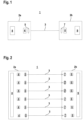
- Figure 1 shows an embodiment of the optical sensor 1 according to the invention in the form of a light barrier.
- the light barrier has a first housing 2a in which a transmitter 4 emitting light rays 3 is arranged, to which a transmitting optics 5 is assigned. Furthermore, the light barrier has a second housing 2b in which a receiver 6 receiving light rays 3 with an upstream receiving optics 7 is arranged.
- the housings 2a, 2b are arranged at opposite edges of a monitoring area such that when the monitoring area is free, the light beams 3 run analogously to a measuring path and hit the receiver 6 unhindered. If an object intervenes in the monitoring area, the light beams 3 are interrupted.
- the transmitter 4 is controlled by a transmitter control 8.
- the receiver 6 is assigned an evaluation unit 9.
- the evaluation unit 9 controls the receiver 6 and evaluates the received signals of the receiver 6, whereby Object detection signal generates a binary switching signal whose switching states indicate whether an object is in the monitoring area or not.
- the evaluation unit 9 can have a multi-channel structure if the light barrier is a safety sensor.
- Figure 2 shows schematically the structure of an embodiment of the optical sensor 1 according to the invention in the form of a light curtain for detecting objects within a monitoring area.
- the light curtain has a first housing 2a with a series arrangement of transmitters 4 emitting light beams 3 and transmitting optics 5 assigned to them.
- the light curtain also has a second housing 2b with a series arrangement of receivers 6 receiving light beams 3, each of which has a receiving optics 7 arranged upstream of it.
- the housings 2a, 2b are arranged on opposite edges of the monitoring area so that a receiver 6 is arranged opposite a transmitter 4.
- This transmitter-receiver pair forms a beam axis.
- six beam axes are provided.
- the light curtain can also have a different number of beam axes.
- the transmitters 4 are controlled by a transmitter control 8.
- An evaluation unit 9 is assigned to the receivers 6.
- the beam axes are activated cyclically one after the other.
- the evaluation unit 9 controls the receivers 6 and evaluates the received signals 6a of the receivers 6 to generate a binary switching signal, the switching states of which indicate whether an object is in the monitoring area or not. In general, this evaluation can not only be carried out in a temporal sequence one after the other for several light beams, but also simultaneously for several light beams. If the monitoring area is clear, the light beams 3 of the beam axes reach the beam axes unhindered. to the receiver 6 of the respective beam axis. If an object is interfered with, at least one beam axis is interrupted.
- the evaluation unit 9 can have a multi-channel structure if the light curtain forms a safety sensor.
- Figure 3a shows an optical sensor 1 in the form of a reflection light barrier.
- the transmitter 4 and the receiver 6 of the optical sensor 1 are, in contrast to the embodiment according to Figure 1 integrated in a common housing 2, which is arranged at one edge of the monitoring area, with a reflector 10 arranged at the opposite edge of the monitoring area.
- the light beams 3 of the transmitter 4 are guided along a measuring path through the monitoring area, reflected at the reflector 10 and from there guided to the receiver 6. Otherwise, the embodiment corresponds to the Figure 3a the embodiment according to Figure 1 .
- Figure 3b shows a variant of the embodiment according to Figure 3a .
- deflecting mirrors 10' are present instead of a reflector 10.
- the deflecting mirrors 10' can be arranged in a housing 2b. With the appropriate arrangement and number of transmitters, receivers and deflecting mirrors 10', more than two light beams 3, 3' can also be arranged.
- Figure 4 shows an optical sensor 1 in the form of a light sensor.
- the transmitter 4 and receiver 6 are integrated in a common housing 2.
- a measuring path with light rays 3 from the transmitter 4 to the receiver 6 is only formed when the light rays 3 are reflected by an object G to be detected and guided back to the receiver 6.
- a binary switching signal is generated in the evaluation unit 9, the switching states of which indicate whether or not an object is present in the monitoring area.
- This embodiment of the optical sensor 1 can also be extended to several transmitter-receiver pairs.
- the or each transmitter 4 emits light beams 3 in the form of sequences of signal sections 11 which are modulated onto the light beams 3.
- An example of this is shown in Figure 5
- the signal sections 11 are modulated with pseudonoise sequences.
- pseudonoise sequences are Barker sequences, Hadamard-Walsh sequences, Kasami sequences, M sequences, Gold sequences or Willard codes.
- the signal sections 11 can also be temporally variable, in particular in the form of chirps, which can be designed as linear or logarithmic chirps.
- these signal sections 11 are stored, i.e. saved or generated.
- the received signal of the or each receiver 6 is correlated with the corresponding stored or generated sequence of signal sections 11 of the transmitter 4 assigned to this receiver 6 in the evaluation unit 9.
- the correlation provides a correlation maximum as correlation result D, since signal sections 11 in the received signal have a high degree of correlation with the sequence of signal sections 11 stored in the evaluation unit 9. If the measuring path is interrupted or there is interference light, this is indicated with a correlation result D that corresponds to a low degree of correlation.
- optical sensor 1 For the optical sensors 1 according to the Figures 1 to 3a , 3b An uninterrupted measuring section is obtained with a free monitoring area. optical sensor 1 according to Figure 4 An uninterrupted measuring path is obtained when the light rays 3 are reflected from the object G back to the receiver 6.
- Figure 6 shows a transmitter control 12 for generating the signal sections 11 in the light beams 3.
- the respective signal sections 11 are stored in digital form in a storage unit 13.
- the signal sections 11 are periodically generated depending on the content of the storage unit 13 and converted in an optionally available n-bit digital-analog converter 15 into an analog signal, which is modulated onto the light beam 3 of the transmitter 4 using a transmission modulator 16.
- the signal sections can be generated using feedback shift registers, for example.
- a post-processing unit may be assigned to the transmitter(s) 4, in which an analog post-processing of the digital signal sections 11 is carried out.
- the post-processing unit can have a bandpass filter or a lowpass filter.
- an offset can be generated in the post-processing unit, through which unipolar analog signal sections 11 are obtained.
- a time-varying offset is particularly advantageous in order to reduce the average current load of the sensor.
- Figure 7 shows a receiving-side circuit arrangement 17 for the optical sensor 1 of the Figures 1 to 4 .
- the light rays 3 strike one of the respective receivers 6.
- Figure 6 only one receiver 6 is shown, according to the embodiments of the Figures 1, 2 , 3a, 3b, 4 .
- the receiving-side circuit arrangement 17 is extended to several receivers 6.
- the received signal generated in the receiver 6 is preprocessed in a preprocessing unit 18.
- the preprocessing unit 18 has a filter unit.
- a synchronization unit 24 can be provided, which determines the phase position of the pulses forming the received signals and the transmitted pulses and determines a sampling time for the pulses.
- Such synchronization can be carried out, for example, with a PLL or DPLL.
- PLL Phase locked loop
- DPLL DPLL
- the preprocessing unit 18 can be used to generate an offset by which unipolar received signals are converted into bipolar received signals by subtraction with a constant preset value. This offset compensation could also take place in the digital part. If synchronization takes place in the receiver, a time-varying offset can also be stored, which is compensated according to the synchronization.
- the reception data obtained in this way are stored in a storage unit 19.
- the storage unit can also be part of the correlator 20. These are fed to a correlation unit 20, which is part of the evaluation unit 9 of the optical sensor 1.
- the correlation unit 20 is also fed from a storage unit 21 with signal sections 11 stored there, which correspond to the signal section 11 of the transmitter 4 assigned to the receiver 6. In the event that several receivers 6 are present, corresponding signal sections 11 are stored in the storage unit 21 for each receiver 6, which are then fed to the correlation unit 20.
- the received signal is correlated with the sequence of signal sections 11 from the storage unit 21.
- the correlation signal D generated in this way is fed to an evaluator 22, which can also be part of the correlation unit 20.
- the correlation result D generated in this way is used in the evaluator 22 to generate the object detection signal, in particular the binary switching signal, which is output via an output 23 of the optical sensor 1.
- the Figures 8a to 8c show an example of this signal evaluation for an optical sensor 1 in the form of a light barrier.
- Figure 8a shows the temporal sequence of the signal sections 11 emitted to the transmitter 4.
- Figure 8b shows the correlation signal obtained in the correlation unit 20.
- Figure 8c shows a result summarized from the individual correlation signals.
- the expectation for a free monitoring area is defined as at least two correlation signals with maximum values with a time interval tSync and all subsequent signals with a time interval tS are registered. If this is the case, the switching output changes from signal state 0 to signal state 1 (corresponding to a free monitoring area), as in Figure 8c shown.
- FIGS 9a to 9c show an example of a signal evaluation for a light curtain with four transmitters 4 (as Figure 8a designated S1 to S4). Each transmitter 4 sends signal sections 11 which are impressed on the light beams 3.
- the first transmitter 4, designated S1 serves for optical synchronization of the light curtain, ie its light beams 3 form a synchronization beam.
- the transmitter 4 S1 sends 2 signal sections 11 at a distance tSync.
- the correlation unit 20 detects two maxima M in the correlation signal separated by tSync ( Figure 9b ) and thereby identifies the light beams 3 of the transmitter S1 as a synchronization beam, thereby generating a synchronization signal ( Figure 9c ). Then, with the other transmitters 4 S2 to S4, an object detection is carried out analogously to the embodiment according to the Figures 8a to 8c .
- a received signal is correlated with the sequence of stored signal sections 11.
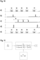
- the Figure 10 shows another embodiment of a signal evaluation for a light curtain with four transmitters 4 (in Figure 10 with S1...S4).
- the first transmitter 4 S1 used for optical synchronization emits signal sections 11a that differ from the signal sections 11b of the other transmitters 4 S2...S4.
- Signal sections 11c which are used as an alternative to 11b, could transmit additional information by means of appropriately coded alternations of 11b and 11c (see e.g. Figure 10e , S2 change 11b to 11c) without affecting the function of detecting the beam interruption.
- the absence of any signal section 11a, 11b or 11c can be used for object detection.
- sequences of 11b, 11c serial data could be transmitted, where 11b would correspond to a logical 1 and 11c to a logical 0, for example.
- Such data coding could of course also be carried out on just one light beam 3 by changing the sequence from cycle to cycle.
- the signal section 11a of the first transmitter 4 is detected and a corresponding correlation signal ( Figure 10b ) and then a synchronization signal ( Figure 10d ) is generated. Then, in the correlation unit 20, correlation signals are generated for the other transmitters 4 S2... S4 ( Figure 10c ), which can be used analogously to the embodiment according to Figure 8 the object detection and the generation of the switching signal takes place.
- the correlation unit 20 the correlation of a received signal with the sequence of the stored signal sections 11 for synchronization, as well as in sequence of the stored signal sections 11b or 11c for detection of the other beams, takes place.
- Figure 11 shows the operation of a correlation unit 20, which is implemented in the form of software modules on a microprocessor or the like.
- correlation functions Y, Y' can be determined for different signal sections 11 in parallel or by switching.
- the correlation functions Y, Y' for generating the correlation signals are, as in Figure 11 specified, calculated from the measured values X[j] and the stored signal sections 11 T[i] or T'[i], whereby correlation results D are obtained.
- Figure 12 shows an embodiment of a correlation unit 20 in the form of an FIR filter.
- the measured values X(k) are fed to the FIR filter with filter coefficients z -1 .
- the signal sections 11 are fed as coefficients h(n).
- the correlation function Y(k) is obtained as a result.
- Figure 13 shows an extension of the embodiment according to Figure 12 .
- the FIR filter according to Figure 13 has a multiplexed structure such that different coefficients h(n) or h(n)' corresponding to different signal sections 11 are activated in a multiplexed manner in the FIR filter, so that both coefficients h(n) and h(n)' are then correlated with the measured values X(k), ie the measured values are correlated with different signal sections in parallel or switched sequentially, whereby two different correlation functions Y(k), Y(k)' are obtained.
- more than two signal sections can also be correlated with the measured values in this way.
- FIGs 14a, 14b show an embodiment in which the light beam 3 is emitted with signal sections 11 in the form of coded sequences of pseudocode sequences C (corresponding to a bit value 1), separated by pauses 0 (during which the transmitter 4 is switched off) ( Figure 14a ).
- the correlation unit 20 calculates the signal section 11 for these signal sections Figure 14b The correlation signal shown with maximum M is obtained.
- the Figures 15a, 15b show an extension of the embodiment of the Figures 14a, 14b in that in the gaps between the pulse code sequences 0 values are not realized by switching off the transmitter 4, but by inverse pseudocode sequences C' in the transmitter 4 ( Figure 14a ).
- the inverse pseudocode sequence C' corresponds to the inverse of the pseudocode sequence C or is derived from it and can be generated much more easily than different signal sections.
- Another advantage is the possibility of transmitting additional information by means of appropriately coded alternations of C and C' without affecting the function of detecting the beam interruption.
- the absence of any M or M' would be used for object detection without pauses deteriorating the system's response time.
- sequences of C, C' serial data could thus be transmitted, where, for example, C or M would correspond to a logical 1 and C' or M' to a logical 0.
- a further improvement in the signal-to-noise ratio is achieved if the pulses that make up the signal sections are particularly narrow and at the same time have a high amplitude, since the pulse amplitudes are then significantly higher than disturbing noise at the same average pulse power.
- Figure 16a shows a signal sequence consisting of pulses with a pulse-pause ratio of approximately 1:1 compared to a noise signal R.
- Figure 16b shows a signal sequence consisting of pulses with the same average power and a pulse-pause ratio of 1:4. Due to the higher pulse amplitude, the pulses are much easier to distinguish from the noise signal R.
- An additional synchronization device 24 determines the temporal positions at which the pulses are expected and samples them accordingly. Such synchronization can be achieved by a phase locked loop (PLL), which is also implemented digitally in FPGA, ASIC or in software (DPLL).
- PLL phase locked loop
Landscapes
- Physics & Mathematics (AREA)
- Life Sciences & Earth Sciences (AREA)
- General Life Sciences & Earth Sciences (AREA)
- General Physics & Mathematics (AREA)
- Geophysics (AREA)
- Geophysics And Detection Of Objects (AREA)
Priority Applications (1)
| Application Number | Priority Date | Filing Date | Title |
|---|---|---|---|
| EP23155484.1A EP4414754A1 (fr) | 2023-02-08 | 2023-02-08 | Capteur optique |
Applications Claiming Priority (1)
| Application Number | Priority Date | Filing Date | Title |
|---|---|---|---|
| EP23155484.1A EP4414754A1 (fr) | 2023-02-08 | 2023-02-08 | Capteur optique |
Publications (1)
| Publication Number | Publication Date |
|---|---|
| EP4414754A1 true EP4414754A1 (fr) | 2024-08-14 |
Family
ID=85202053
Family Applications (1)
| Application Number | Title | Priority Date | Filing Date |
|---|---|---|---|
| EP23155484.1A Pending EP4414754A1 (fr) | 2023-02-08 | 2023-02-08 | Capteur optique |
Country Status (1)
| Country | Link |
|---|---|
| EP (1) | EP4414754A1 (fr) |
Citations (3)
| Publication number | Priority date | Publication date | Assignee | Title |
|---|---|---|---|---|
| EP2103962B1 (fr) * | 2008-03-20 | 2011-08-17 | Sick Ag | Capteur optoélectronique |
| DE102011000855A1 (de) * | 2011-02-21 | 2012-08-23 | Sick Ag | Optoelektronischer Sensor und Verfahren zur Erfassung von Objekten |
| EP2015110B1 (fr) * | 2007-07-10 | 2013-04-17 | Sick Ag | Capteur optoélectronique |
-
2023
- 2023-02-08 EP EP23155484.1A patent/EP4414754A1/fr active Pending
Patent Citations (3)
| Publication number | Priority date | Publication date | Assignee | Title |
|---|---|---|---|---|
| EP2015110B1 (fr) * | 2007-07-10 | 2013-04-17 | Sick Ag | Capteur optoélectronique |
| EP2103962B1 (fr) * | 2008-03-20 | 2011-08-17 | Sick Ag | Capteur optoélectronique |
| DE102011000855A1 (de) * | 2011-02-21 | 2012-08-23 | Sick Ag | Optoelektronischer Sensor und Verfahren zur Erfassung von Objekten |
Similar Documents
| Publication | Publication Date | Title |
|---|---|---|
| EP1949143B1 (fr) | Dispositif et procede pour surveiller une zone de l'espace, en particulier pour securiser une zone a risques d'une installation automatisee | |
| DE60027066T2 (de) | Auf eine Korrelation basierender optischer Entfernungsmess- und Näherungssensor | |
| EP0503040B1 (fr) | Dispositif capteur optique et son procede d'exploitation | |
| DE102012112985B3 (de) | Entfernungsmessender optoelektronischer Sensor und Verfahren zur Erfassung und Abstandsbestimmung von Objekten | |
| EP3014313B1 (fr) | Procédé de synchronisation d'une barrière lumineuse | |
| DE4141469C2 (de) | Verfahren zum Betrieb einer optischen Sensoranordnung zur Feststellung von in einem Überwachungsbereich vorhandenen Gegenständen sowie eine solche optische Sensoranordnung | |
| DE10355008B4 (de) | Verfahren zur Verarbeitung eines Empfangssignals und optischer Sensor | |
| EP1933173B1 (fr) | Barrière lumineuse | |
| DE10211387B4 (de) | Strahlungsimpulse verwendender Sensor | |
| EP2278359B1 (fr) | Procédé de fonctionnement de barrières lumineuses | |
| DE102004031024B4 (de) | Optischer Sensor | |
| EP4414754A1 (fr) | Capteur optique | |
| EP3796052B1 (fr) | Agencement de capteur optoélectronique et système de capteur | |
| EP3147694B1 (fr) | Procede de fonctionnement d'un capteur photoelectrique et capteur photoelectrique | |
| EP4435478A1 (fr) | Capteur optique et procédé de fonctionnement d'un capteur optique | |
| DE19506390A1 (de) | Entfernungsmeßgerät | |
| DE102004050627B4 (de) | Verfahren und Entfernungsmessvorrichtung zum Bestimmen der Entfernung zwischen einem Objekt und der Vorrichtung | |
| EP2490045B1 (fr) | Capteur optoélectronique et procédé destiné à la détection d'objets | |
| EP3614182B1 (fr) | Système de barrière lumineuse | |
| EP4224218B1 (fr) | Ensemble barrière lumineuse | |
| DE102022213906A1 (de) | Verfahren zum Betreiben eines medizinischen optischen Trackingsystems und medizinisches optisches Trackingsystem | |
| DE102011014195B4 (de) | Optischer Sensor | |
| DE4237347C1 (de) | Verfahren und Schaltungsanordnung zur Erfassung und Auwertung von Signalen bei der Messung von Entfernungen und Entfernungsänderungen | |
| EP3822667B1 (fr) | Agencement de barrières lumineuses | |
| EP1524534B1 (fr) | Capteur optique |
Legal Events
| Date | Code | Title | Description |
|---|---|---|---|
| PUAI | Public reference made under article 153(3) epc to a published international application that has entered the european phase |
Free format text: ORIGINAL CODE: 0009012 |
|
| STAA | Information on the status of an ep patent application or granted ep patent |
Free format text: STATUS: REQUEST FOR EXAMINATION WAS MADE |
|
| 17P | Request for examination filed |
Effective date: 20230816 |
|
| AK | Designated contracting states |
Kind code of ref document: A1 Designated state(s): AL AT BE BG CH CY CZ DE DK EE ES FI FR GB GR HR HU IE IS IT LI LT LU LV MC ME MK MT NL NO PL PT RO RS SE SI SK SM TR |
|
| P01 | Opt-out of the competence of the unified patent court (upc) registered |
Free format text: CASE NUMBER: APP_47979/2024 Effective date: 20240821 |
|
| STAA | Information on the status of an ep patent application or granted ep patent |
Free format text: STATUS: EXAMINATION IS IN PROGRESS |
|
| 17Q | First examination report despatched |
Effective date: 20260216 |