EP4416464B1 - Méthode d'utilisation d'un système de propulsion linéaire et système de propulsion linéaire - Google Patents
Méthode d'utilisation d'un système de propulsion linéaire et système de propulsion linéaire Download PDFInfo
- Publication number
- EP4416464B1 EP4416464B1 EP22817747.3A EP22817747A EP4416464B1 EP 4416464 B1 EP4416464 B1 EP 4416464B1 EP 22817747 A EP22817747 A EP 22817747A EP 4416464 B1 EP4416464 B1 EP 4416464B1
- Authority
- EP
- European Patent Office
- Prior art keywords
- magnetic field
- sensor
- magnet
- sensor device
- partial
- Prior art date
- Legal status (The legal status is an assumption and is not a legal conclusion. Google has not performed a legal analysis and makes no representation as to the accuracy of the status listed.)
- Active
Links
Images







Classifications
-
- G—PHYSICS
- G01—MEASURING; TESTING
- G01D—MEASURING NOT SPECIALLY ADAPTED FOR A SPECIFIC VARIABLE; ARRANGEMENTS FOR MEASURING TWO OR MORE VARIABLES NOT COVERED IN A SINGLE OTHER SUBCLASS; TARIFF METERING APPARATUS; MEASURING OR TESTING NOT OTHERWISE PROVIDED FOR
- G01D5/00—Mechanical means for transferring the output of a sensing member; Means for converting the output of a sensing member to another variable where the form or nature of the sensing member does not constrain the means for converting; Transducers not specially adapted for a specific variable
- G01D5/12—Mechanical means for transferring the output of a sensing member; Means for converting the output of a sensing member to another variable where the form or nature of the sensing member does not constrain the means for converting; Transducers not specially adapted for a specific variable using electric or magnetic means
- G01D5/14—Mechanical means for transferring the output of a sensing member; Means for converting the output of a sensing member to another variable where the form or nature of the sensing member does not constrain the means for converting; Transducers not specially adapted for a specific variable using electric or magnetic means influencing the magnitude of a current or voltage
- G01D5/142—Mechanical means for transferring the output of a sensing member; Means for converting the output of a sensing member to another variable where the form or nature of the sensing member does not constrain the means for converting; Transducers not specially adapted for a specific variable using electric or magnetic means influencing the magnitude of a current or voltage using Hall-effect devices
- G01D5/145—Mechanical means for transferring the output of a sensing member; Means for converting the output of a sensing member to another variable where the form or nature of the sensing member does not constrain the means for converting; Transducers not specially adapted for a specific variable using electric or magnetic means influencing the magnitude of a current or voltage using Hall-effect devices influenced by the relative movement between the Hall device and magnetic fields
-
- G—PHYSICS
- G01—MEASURING; TESTING
- G01D—MEASURING NOT SPECIALLY ADAPTED FOR A SPECIFIC VARIABLE; ARRANGEMENTS FOR MEASURING TWO OR MORE VARIABLES NOT COVERED IN A SINGLE OTHER SUBCLASS; TARIFF METERING APPARATUS; MEASURING OR TESTING NOT OTHERWISE PROVIDED FOR
- G01D18/00—Testing or calibrating apparatus or arrangements provided for in groups G01D1/00 - G01D15/00
- G01D18/001—Calibrating encoders
-
- G—PHYSICS
- G01—MEASURING; TESTING
- G01D—MEASURING NOT SPECIALLY ADAPTED FOR A SPECIFIC VARIABLE; ARRANGEMENTS FOR MEASURING TWO OR MORE VARIABLES NOT COVERED IN A SINGLE OTHER SUBCLASS; TARIFF METERING APPARATUS; MEASURING OR TESTING NOT OTHERWISE PROVIDED FOR
- G01D5/00—Mechanical means for transferring the output of a sensing member; Means for converting the output of a sensing member to another variable where the form or nature of the sensing member does not constrain the means for converting; Transducers not specially adapted for a specific variable
- G01D5/12—Mechanical means for transferring the output of a sensing member; Means for converting the output of a sensing member to another variable where the form or nature of the sensing member does not constrain the means for converting; Transducers not specially adapted for a specific variable using electric or magnetic means
- G01D5/244—Mechanical means for transferring the output of a sensing member; Means for converting the output of a sensing member to another variable where the form or nature of the sensing member does not constrain the means for converting; Transducers not specially adapted for a specific variable using electric or magnetic means influencing characteristics of pulses or pulse trains; generating pulses or pulse trains
- G01D5/24471—Error correction
- G01D5/2449—Error correction using hard-stored calibration data
-
- H—ELECTRICITY
- H02—GENERATION; CONVERSION OR DISTRIBUTION OF ELECTRIC POWER
- H02K—DYNAMO-ELECTRIC MACHINES
- H02K11/00—Structural association of dynamo-electric machines with electric components or with devices for shielding, monitoring or protection
- H02K11/20—Structural association of dynamo-electric machines with electric components or with devices for shielding, monitoring or protection for measuring, monitoring, testing, protecting or switching
- H02K11/21—Devices for sensing speed or position, or actuated thereby
- H02K11/215—Magnetic effect devices, e.g. Hall-effect or magneto-resistive elements
-
- H—ELECTRICITY
- H02—GENERATION; CONVERSION OR DISTRIBUTION OF ELECTRIC POWER
- H02K—DYNAMO-ELECTRIC MACHINES
- H02K41/00—Propulsion systems in which a rigid body is moved along a path due to dynamo-electric interaction between the body and a magnetic field travelling along the path
- H02K41/02—Linear motors; Sectional motors
- H02K41/03—Synchronous motors; Motors moving step by step; Reluctance motors
- H02K41/031—Synchronous motors; Motors moving step by step; Reluctance motors of the permanent magnet type
-
- H—ELECTRICITY
- H02—GENERATION; CONVERSION OR DISTRIBUTION OF ELECTRIC POWER
- H02P—CONTROL OR REGULATION OF ELECTRIC MOTORS, ELECTRIC GENERATORS OR DYNAMO-ELECTRIC CONVERTERS; CONTROLLING TRANSFORMERS, REACTORS OR CHOKE COILS
- H02P25/00—Arrangements or methods for the control of AC motors characterised by the kind of AC motor or by structural details
- H02P25/02—Arrangements or methods for the control of AC motors characterised by the kind of AC motor or by structural details characterised by the kind of motor
- H02P25/06—Linear motors
-
- H—ELECTRICITY
- H02—GENERATION; CONVERSION OR DISTRIBUTION OF ELECTRIC POWER
- H02P—CONTROL OR REGULATION OF ELECTRIC MOTORS, ELECTRIC GENERATORS OR DYNAMO-ELECTRIC CONVERTERS; CONTROLLING TRANSFORMERS, REACTORS OR CHOKE COILS
- H02P6/00—Arrangements for controlling synchronous motors or other dynamo-electric motors using electronic commutation dependent on the rotor position; Electronic commutators therefor
- H02P6/14—Electronic commutators
- H02P6/16—Circuit arrangements for detecting position
-
- B—PERFORMING OPERATIONS; TRANSPORTING
- B65—CONVEYING; PACKING; STORING; HANDLING THIN OR FILAMENTARY MATERIAL
- B65G—TRANSPORT OR STORAGE DEVICES, e.g. CONVEYORS FOR LOADING OR TIPPING, SHOP CONVEYOR SYSTEMS OR PNEUMATIC TUBE CONVEYORS
- B65G54/00—Non-mechanical conveyors not otherwise provided for
- B65G54/02—Non-mechanical conveyors not otherwise provided for electrostatic, electric, or magnetic
-
- G—PHYSICS
- G01—MEASURING; TESTING
- G01D—MEASURING NOT SPECIALLY ADAPTED FOR A SPECIFIC VARIABLE; ARRANGEMENTS FOR MEASURING TWO OR MORE VARIABLES NOT COVERED IN A SINGLE OTHER SUBCLASS; TARIFF METERING APPARATUS; MEASURING OR TESTING NOT OTHERWISE PROVIDED FOR
- G01D2205/00—Indexing scheme relating to details of means for transferring or converting the output of a sensing member
- G01D2205/10—Detecting linear movement
- G01D2205/18—Detecting linear movement using magnetic means not otherwise provided for in this subclass
-
- H—ELECTRICITY
- H02—GENERATION; CONVERSION OR DISTRIBUTION OF ELECTRIC POWER
- H02P—CONTROL OR REGULATION OF ELECTRIC MOTORS, ELECTRIC GENERATORS OR DYNAMO-ELECTRIC CONVERTERS; CONTROLLING TRANSFORMERS, REACTORS OR CHOKE COILS
- H02P2207/00—Indexing scheme relating to controlling arrangements characterised by the type of motor
- H02P2207/05—Synchronous machines, e.g. with permanent magnets or DC excitation
Definitions
- the present invention relates to a method for operating a linear drive system.
- the drive system comprises a primary part and a secondary part, which are translationally movable relative to one another.
- the method involves determining the position of the primary part.
- the invention further relates to a linear drive system.
- a linear drive system enables the generation of a linear translational movement.
- Such a system can be used in a variety of applications, for example, to generate a translational movement of a machine element or a system component.
- the movement can be generated based on a magnetic or electromagnetic principle.
- the drive system which can also be referred to as a linear motor, can have a primary part and a secondary part.
- the primary part and the secondary part can be moved translationally relative to one another.
- the secondary part can be stationary and the primary part can be moved relative to the secondary part.
- the primary part can have an energizable electromagnet device, and the secondary part can have a magnet arrangement made up of permanent magnets arranged next to one another. By energizing the electromagnet device of the primary part, a magnetic interaction can be induced between the electromagnet device and the magnet arrangement, and thus a movement of the primary part and the secondary part relative to one another.
- a suitable measuring device can be used in addition to the primary part and secondary part used for the drive.
- Examples include a magnetostrictive linear measuring system, as well as an optical, inductive, or magnetic linear scale. This requires the use of additional attachments and is associated with a corresponding space requirement.
- the EP 3 883 124 A1 describes a planar drive system and a method for controlling the same.
- the planar drive system comprises a stator module with energizable stator conductors and a permanently excited rotor with a magnet arrangement. By energizing the stator conductors of the stator module, a magnetic interaction with the magnet arrangement of the rotor can be induced to drive and move the rotor.
- the stator module comprises a sensor module with magnetic field sensors for detecting a rotor magnetic field of the rotor. This serves to detect the position of the rotor.
- the DE 10 2019 118 442 A1 describes a linear direct drive comprising a guide with permanent magnets and a movable carriage with electromagnets, as well as a method for determining an absolute position of the carriage.
- a position measuring system provided on the carriage, which comprises at least one magnetic field sensor or a sensor array, an evaluator, and a memory.
- magnetic field characteristics are recorded at several carriage positions using the at least one magnetic field sensor and stored in the memory as reference characteristics linked to the carriage positions.
- a magnetic field characteristic is detected using the at least one magnetic field sensor, which is compared in the evaluator with the stored reference characteristics. If the detected magnetic field characteristic is correlated with a reference characteristic, the carriage position associated with the reference characteristic is output as the current carriage position.
- the object of the present invention is to provide an improved method for operating a linear drive system. It is also an object of the invention to provide a correspondingly designed linear drive system.
- the proposed method enables reliable and accurate position determination for the primary part of the linear drive system.
- the secondary part of the drive system already used for the motion drive, is used together with the sensor device consisting of magnetic field sensors provided on the primary part. This allows for position determination without the need for bulky attachments, thus saving space and being cost-effective.
- the method exploits the fact that the magnetic field generated by the permanent magnet arrangement of the secondary part and detected by the sensor device of the primary part can have a substantially periodic profile with individual differences along a direction of movement in which the primary part and secondary part can move relative to each other.
- the cause of these differences can be tolerances inherent in the linear drive system and its components. These can include mechanical and magnetic angular errors, magnetization errors, density differences, geometric deviations, adhesive gaps, mechanical misalignment, etc.
- the magnetic field of the magnet arrangement of the secondary part is recorded at different positions of the primary part in relation to the secondary part using the sensor device. Based on this data or on the measurement data obtained by recording the magnetic field, position-dependent reference magnetic field data is provided.
- the reference magnetic field data can contain and represent the position-dependent differences in the recorded magnetic field of the magnet arrangement of the secondary part. In other words, a magnetic fingerprint of one or more permanent magnets of the secondary part can be recorded through the initial measurement.
- the magnetic field of the magnet arrangement of the secondary part is recorded again using the sensor device of the primary part. Based on this, current magnetic field data is provided. An evaluation carried out on the basis of the reference magnetic field data and the current magnetic field data can therefore be used to determine the current position of the primary part in relation to the secondary part.
- the translational movement of the primary part and the secondary part relative to each other can take place along a predetermined direction of movement.
- the linear drive system is designed such that the secondary part is a stationary component and the primary part is a movable component of the drive system, wherein the primary part can be moved relative to the secondary part due to the magnetic interaction between the electromagnet device of the primary part and the magnet arrangement of the secondary part.
- An inverse design is also possible, in which the primary part represents a stationary component and the secondary part is a movable component of the drive system, wherein the secondary part can be moved relative to the primary part due to the magnetic interaction between the electromagnet device of the primary part and the magnet arrangement of the secondary part.
- the position of the primary part with respect to the secondary part can be determined by carrying out the method.
- the respective moving component of the linear drive system can be (initially) stationary. Furthermore, the current position can be determined, for example, after a restart or after a power failure of the linear drive system.
- the electromagnet device of the primary part can comprise a plurality of energizable electromagnets.
- the electromagnets can be implemented in the form of coils.
- a varying magnetic field can be generated with the aid of the electromagnet device. This field can interact with the magnetic field generated by the magnet arrangement of the secondary part in such a way as to cause the primary part and the secondary part to move relative to one another.
- the magnet arrangement of the secondary part comprises several permanent magnets arranged side by side. Adjacent and consecutive permanent magnets can be arranged opposite to each other in terms of their polarity, resulting in a polarity reversal along the direction of movement of the primary part and secondary part. Thus, permanent magnet pairs consisting of permanent magnets with mutually inverse polarities can be present along the direction of movement.
- the permanent magnets of the magnet arrangement can have an elongated shape and be arranged parallel to one another with respect to their longitudinal axes.
- the longitudinal axes of the permanent magnets can be oriented substantially perpendicular to the direction of movement. Deviating from a precisely perpendicular orientation, an oblique or slightly oblique orientation of the longitudinal axes of the permanent magnets with respect to the direction of movement can be provided in order to suppress the occurrence of cogging during movement.
- the sensor device of the primary part which serves to detect the magnetic field of the permanent magnet arrangement of the secondary part, has several magnetic field sensors.
- the magnetic field sensors are Hall sensors.
- other sensors such as MR sensors (magnetoresistive sensors) can be used.
- the magnetic field sensors can be designed to measure the magnetic field or the magnetic flux density in different directions, for example, in three different directions.
- the magnetic field sensors can be arranged distributed in one or more planes. Furthermore, the magnetic field sensors can be arranged distributed relative to one another and spaced apart from one another with respect to the direction of movement of the primary part and secondary part.
- the linear drive system may include additional components. These include, for example, components that can be used to guide or support the movable primary part (or the movable secondary part in the case of an inverse design). Examples of these include guide rails with movable rollers or balls, as well as corresponding retaining elements.
- the linear drive system comprises a main control device configured to control the operation of the drive system.
- the main control device can be connected to the primary part via a cable, which, in the case of a movable design of the primary part, can be implemented as a trailing cable or cable drag chain.
- the main control device can be used to control the energization of the electromagnet device of the primary part, and thus the movement of the primary part and secondary part relative to one another.
- the initial measurement and position determination can also be controlled with the aid of the main control device or carried out with the involvement of the main control device.
- the reference magnetic field data as well as the current magnetic field data which can be obtained by detecting the magnetic field of the magnet arrangement of the secondary part using the sensor device, can be stored in the main control device. Based on the reference magnetic field data and the current magnetic field data, the main control device can determine the current position of the primary part with respect to the secondary part.
- the embodiments of the method described below can also be carried out by the main control device or can be carried out as part of an evaluation by the main control device.
- the position determination comprises performing a comparison of at least part of the current magnetic field data with parts of the reference magnetic field data using a similarity method.
- a similarity method which can also be referred to as a correlation method, the position determination can be carried out with a high degree of reliability and accuracy.
- data sets or partial data sets can be compared with one another.
- at least one partial data set of the current magnetic field data can be compared with several partial data sets of the reference magnetic field data.
- the partial data sets of the reference magnetic field data can represent different positions of the primary part relative to the secondary part, so that the current position of the primary part can be determined at least roughly based on the comparison.
- the similarity method used is a DTW (Dynamic Time Warping) method.
- the DTW method enables reliable position determination with a high degree of simplicity and can therefore be reliably performed even with data sets with a relatively small number of data points.
- a further advantage is its high degree of flexibility, which allows data sets to be reliably compared even if they have different numbers of data points or a temporal or spatial offset, for example, due to a sampling used in magnetic field detection.
- the similarity of two data sets to be compared can be determined.
- the method can include steps such as generating a distance matrix and determining the most efficient path through the distance matrix.
- the method can also determine a similarity measure, the so-called DTW distance. The smaller the DTW distance, the more similar the compared data sets are.
- the reference magnetic field data comprises a plurality of magnetic field patterns.
- the magnetic field patterns which represent partial data sets of the reference magnetic field data, are each assigned to a magnet group consisting of adjacently arranged permanent magnets of the magnet arrangement.
- the comparison can be performed using the magnetic field patterns. This allows for position determination with a high degree of reliability and accuracy.
- the permanent magnets of the magnet arrangement of the secondary part are divided into several magnet groups.
- the magnet groups, each of which has a magnetic field pattern can, for example, each comprise two permanent magnets arranged next to one another and polarized inversely to one another, and thus each comprise a permanent magnet pair. It can further be provided that the magnet groups each comprise a larger number of permanent magnets or permanent magnet pairs, for example four permanent magnets arranged next to one another and thus two permanent magnet pairs arranged next to one another.
- the sensor device of the primary part can be designed in terms of its dimensions such that, with the aid of the magnetic field sensors, an overlap of one or more permanent magnet pairs and thus an overlap of a magnet group, based on the direction of movement of the primary part and secondary part, can be achieved.
- the magnetic field patterns which can also be referred to as reference patterns or templates, can be used in the comparison with the current magnetic field data.
- Performing the comparison can comprise at least one of the following: comparing the current magnetic field data with the magnetic field patterns; comparing at least a part (i.e., at least one partial data set) of the current magnetic field data with at least one partial pattern of the magnetic field patterns; comparing the current magnetic field data with magnetic field patterns newly composed from the magnetic field patterns (or from parts or partial patterns thereof); and/or comparing multiple parts or partial data sets of the current magnetic field data with partial patterns of the magnetic field patterns. Possible embodiments for this are explained in more detail below.
- the primary part and the secondary part are moved relative to one another during the initial measurement.
- the magnetic field patterns are provided based on the detected magnetic field of the magnet arrangement of the secondary part, which is detected with the aid of the sensor device when the magnetic field sensors of the sensor device are each located in the area of a magnet group.
- a magnetic field pattern for a magnet group is provided based on the detected magnetic field whenever there is overlap of the respective magnet group by the magnetic field sensors, based on the direction of movement of the primary part and secondary part.
- the magnetic field patterns can be provided in a simple manner.
- the magnetic field patterns can be stored in the main control device of the linear drive system.
- the end-side magnetic field sensor is located, relative to the direction of movement of the primary part and secondary part, at one end or edge of the arrangement of magnetic field sensors of the sensor device.
- the magnetic field component taken into account can be detected in a direction oriented perpendicular to the direction of movement of the movable primary part (or the movable secondary part in the case of an inverse embodiment).
- the zero crossings can represent boundaries of adjacent permanent magnets and permanent magnet pairs of the magnet arrangement of the secondary part, which can be used to determine whether the magnetic field sensors of the sensor device are located in the area of a magnet group. If the end-side magnetic field sensor is located at or near a boundary, thus resulting in a magnet group being covered by the magnetic field sensors of the sensor device, this can be detected by a zero crossing of the magnetic field component detected by the end-side magnetic field sensor.
- the provision of the magnetic field patterns can be coordinated with this.
- the magnetic field sensors of the sensor device are located in the current position of the primary part within the range of a magnet group of the magnet arrangement of the secondary part, thus resulting in overlap of the magnet group by the magnetic field sensors.
- the magnetic field sensors of the sensor device are located in the current position of the primary part within the range of a magnet group of the magnet arrangement of the secondary part, thus resulting in overlap of the magnet group by the magnetic field sensors.
- the magnetic field patterns assigned to the magnet groups it is possible to determine a magnetic field pattern with the greatest similarity, thereby determining the associated magnet group, thus positioning the sensor device at the relevant magnet group, and consequently the current position of the primary part.
- the sensor device in the current position of the primary part, can also be offset in the area of two adjacent magnet groups of the magnet arrangement of the secondary part, so that the two magnet groups are each partially covered by the sensor device with respect to the direction of movement of the primary part and secondary part.
- the comparison can be coordinated accordingly or performed with coordinated data, as explained further below.
- the position determination comprises determining a sensor position of the sensor device relative to a boundary between two adjacent magnet groups or between two adjacent permanent magnet pairs in the current position of the primary part. Furthermore, the position of the primary part is determined or the comparison is performed taking into account the determined sensor position of the sensor device. In this way, for example, an offset positioning of the sensor device in the region of two adjacent magnet groups can be taken into account, and even in such a case, an accurate position determination can be achieved.
- the sensor position of the sensor device is determined based on a zero crossing of a profile of a magnetic field component of the magnetic field of the magnet arrangement of the secondary part, which is represented by the current magnetic field data.
- the magnetic field component taken into account can be the magnetic field component that is detected in a direction oriented perpendicular to the direction of movement of the primary part and secondary part.
- a boundary between two adjacent magnet groups or permanent magnet pairs can be detected based on a zero crossing in the profile of the magnetic field component represented by the current magnetic field data, and the sensor position of the sensor device can thus be determined with respect to such a boundary.
- a sensor position can be detected in which the sensor device is located in the region of a magnet group or a magnet group can be covered by the sensor device. If this is not the case or if, in the observed profile of the magnetic field component, there is a zero crossing coinciding with a boundary between adjacent magnet groups or permanent magnet pairs, a sensor position can be detected in which the sensor device is located in the region of two adjacent magnet groups and the adjacent magnet groups can be partially covered by the sensor device.
- Determining the sensor position with respect to a boundary between two adjacent magnet groups or permanent magnet pairs of the magnet arrangement of the secondary part can further comprise determining a distance, relative to the direction of movement, between the boundary and one or more magnetic field sensors of the sensor device arranged closest to the boundary in the current position of the primary part.
- one or more magnetic field sensors arranged closest to the boundary can be identified based on the course of the magnetic field component and the zero crossing represented by the current magnetic field data. Based on this, or by performing an interpolation or extrapolation, the distance between the boundary and one or more magnetic field sensors arranged closest to the boundary can be determined.
- the interpolation or extrapolation can be carried out taking into account a distance between magnetic field sensors of the sensor device.
- the sensor device can cover a boundary between the adjacent magnet groups, and several or two magnetic field sensors located closest to the boundary can be arranged on either side of the boundary.
- an interpolation or extrapolation can be performed to determine the distance between the boundary and one or more magnetic field sensors located closest to the boundary, taking into account the distance between the respective magnetic field sensors.
- all magnetic field sensors can be arranged equidistantly from one another with respect to the direction of movement.
- the method step described above can be performed using a uniform distance between the magnetic field sensors.
- the magnetic field sensors can also be arranged non-equidistantly, whereby the aforementioned step can be performed using the corresponding distance between the respective magnetic field sensors in order to achieve the appropriate accuracy.
- the distance between the magnetic field sensors can be determined as follows. A total distance, related to the direction of movement, between the end-side magnetic field sensors of the sensor device, which are located at opposite ends of the arrangement of magnetic field sensors, can be provided, for example, by measuring the sensor device. Furthermore, phase shifts of the profiles of a signal generated with the aid of the magnetic field sensors can be determined. detected magnetic field component of the magnetic field of the magnet arrangement of the secondary part can be determined. This can be carried out as part of the initial measurement, in which the primary part and the secondary part can be moved relative to one another as stated above.
- the magnetic field component can be the magnetic field component that is detected in a direction oriented perpendicular to the direction of movement.
- a positioning of the sensor device in the area of a magnet group of the magnet arrangement of the secondary part, such that the magnet group is covered by the magnetic field sensors, can be detected, as stated above, by determining the sensor position of the sensor device in relation to a boundary between two adjacent magnet groups or two adjacent permanent magnet pairs.
- the boundary can be present in the area of an edge or end of the sensor device. This can be determined based on a profile of a magnetic field component of the magnetic field of the magnet arrangement of the secondary part, which is represented by the current magnetic field data.
- the relevant magnetic field component can be detected in a direction oriented perpendicular to the direction of movement of the primary part and secondary part.
- a sensor position of the sensor device in the area of a magnet group can be detected in this case by the fact that in the relevant profile of the magnetic field component, at least in the area of its ends, there is no zero crossing coinciding with a boundary between adjacent magnet groups or permanent magnet pairs.
- the current magnetic field data can be compared with the magnetic field patterns of the reference magnetic field data to determine the position of the primary part in order to determine a magnetic field pattern with the greatest similarity, and thus the associated magnet group.
- the distance, relative to the direction of movement, between a boundary of adjacent magnet groups or permanent magnet pairs and a magnetic field sensor located closest to the boundary can also be determined.
- an extrapolation can be performed using the profile of the magnetic field component represented by the current magnetic field data.
- the sensor device in the current position of the primary part, is located in the area of two adjacent magnet groups, so that both magnet groups are each partially covered by the sensor device. If such a sensor position is present, the following embodiment can be used with regard to carrying out the comparison.
- a partial data set is formed from the current magnetic field data, which was acquired with the aid of a sensor subgroup of magnetic field sensors of the sensor device, by means of which the partial coverage of one of the two magnet groups is established.
- partial patterns are formed from the magnetic field patterns, taking the partial coverage into account.
- the partial data set of the current magnetic field data is compared with the partial patterns of the magnetic field patterns.
- a partial coverage of a magnet group by a part of the sensor device, determined based on the sensor position, is taken into account.
- a sensor subgroup comprising magnetic field sensors of the sensor device is located in the area of the relevant magnet group, and the magnet group is thus covered by the sensor subgroup.
- a partial data set is selected from the current magnetic field data, which was obtained using the sensor subgroup covering the magnet group.
- partial patterns relating to the partial coverage are formed from the magnetic field patterns.
- the magnetic field patterns each relate to a magnet group of the magnet arrangement of the secondary part.
- the partial patterns formed therefrom reflect the partial coverage determined based on the sensor position and caused by the sensor subgroup with respect to each of the magnet groups linked to the magnetic field patterns.
- the partial data set of the current magnetic field data is compared with the partial patterns of the magnetic field patterns. This allows a partial pattern and, consequently, a magnetic field pattern with the greatest similarity to be determined, thereby identifying the associated magnet group and, thus, positioning the sensor device at the relevant magnet group. Based on this, or by additionally considering the sensor position of the sensor device, the current position of the primary part can be determined.
- the formation of the partial data set from the current magnetic field data and the formation of the partial patterns from the magnetic field patterns can be performed with reference to the larger partial coverage and larger sensor subgroup of magnetic field sensors in order to achieve high accuracy.
- the following procedure is used when a sensor position of the sensor device is determined to be in the range of two adjacent magnet groups, such that both magnet groups are partially covered by the sensor device.
- Composite magnetic field patterns are formed, each of which is composed of partial patterns of magnetic field patterns of two adjacent magnet groups, taking into account the partial overlaps.
- the current magnetic field data is compared with the composite magnetic field patterns.
- an overlap between two adjacent magnet groups determined based on the sensor position, whereby both magnet groups are partially overlapped by the sensor device is taken into account.
- partial patterns of magnetic field patterns relating to the partial overlaps, each relating to two adjacent magnet groups, are selected and combined to form new magnetic field patterns.
- the newly combined magnetic field patterns reflect the positioning of the sensor device determined based on the sensor position and thus the overlap achieved by the sensor device with respect to two adjacent magnet groups.
- the current magnetic field data are compared with the composite magnetic field patterns. This allows a composite magnetic field pattern with the greatest similarity to be determined, thereby identifying the two neighboring magnet groups belonging to the composite magnetic field pattern, and thus positioning the sensor device at the respective two magnet groups. Based on this, or by additionally considering the sensor position of the sensor device, the current position of the primary part can be determined.
- the embodiment of the method explained below can also be used if, in the current position of the primary part, a sensor position of the sensor device in the area of two adjacent magnet groups is present or detected, and thus both magnet groups are each partially covered by the sensor device.
- the current magnetic field data is divided into partial data sets, each of which was acquired using a sensor subgroup of magnetic field sensors of the sensor device that partially covers the magnet arrangement. Furthermore, partial patterns are formed from the magnetic field patterns, taking into account the sensor position of the sensor device and the partial coverage by the sensor subgroups. To perform the comparison, the partial data sets are compared with the partial patterns.
- the aforementioned embodiment is based on a division of the magnetic field sensors of the sensor device into several sensor subgroups, each of which partially covers the magnet arrangement of the secondary part.
- the sensor subgroups can each comprise the same number of magnetic field sensors.
- several partial data sets are selected from the current magnetic field data, which were obtained using the sensor subgroups that partially cover the magnet arrangement.
- partial patterns relating to the partial coverages are formed from the magnetic field patterns. With the aid of the partial patterns, the partial coverages caused by the sensor subgroups can be reproduced in relation to two adjacent magnet groups.
- those partial patterns that represent the partial coverage caused by this sensor subgroup can be created by assembling parts of Magnetic field patterns are formed by neighboring magnet groups.
- several sensor subgroups can also overlap the boundary.
- the subpatterns relating to the partial overlaps of these sensor subgroups can be composed of parts of the magnetic field patterns of neighboring magnet groups.
- the partial data sets are compared with the respective subpatterns in terms of sensor position and distribution of the magnetic field sensors, and thus the partial overlaps caused by the sensor subgroups.
- the subpatterns with the greatest similarity can be identified. This makes it possible to determine the two neighboring magnet groups and thus the positioning of the sensor device at those two neighboring magnet groups that belong to the identified subpatterns. Based on this, or with additional consideration of the sensor position of the sensor device, the current position of the primary part can be determined.
- the aforementioned embodiment in which multiple partial data sets are compared with multiple partial patterns, can further improve the reliability and accuracy of position determination. Furthermore, this embodiment also enables a plausibility check. This requires that two neighboring magnet groups be determined in a consistent manner based on the partial patterns determined with the greatest similarity. If this is not the case, it can be concluded that an error exists, for example, in the data used.
- a division of the permanent magnets of the magnet arrangement of the secondary part can be provided, according to which the magnet groups each comprise several permanent magnet pairs of inversely polarized permanent magnets.
- the sensor device of the primary part can be designed in terms of dimensions such that with the aid of the magnetic field sensors, a Overlap of such a magnet group, relative to the direction of movement of the primary part and secondary part, can be achieved. It is possible for the sensor device, in the current position of the primary part and in the presence of an offset sensor position, to cover several boundaries of adjacent permanent magnet pairs or magnet groups. This can be determined accordingly based on zero crossings of a profile of a magnetic field component of the magnetic field of the magnet arrangement of the secondary part, represented by the current magnetic field data.
- the method variants for position determination explained above can be carried out with reference to one of the boundaries.
- the current position of the primary part relative to the secondary part can be a stationary position, so that when this position is present, no movement is generated in the linear drive system. Starting from this position, the primary part and the secondary part can be moved relative to one another.
- the current position determined according to the method can be used as a reference position to which subsequently performed movements and thus position changes of the primary part relative to the secondary part can be referenced.
- the position changes can be determined based on the magnetic field of the magnet arrangement of the secondary part, which is detected with the aid of one or more magnetic field sensors of the sensor device. This can be done incrementally, for example, by determining the position changes relative to individual permanent magnet pairs or magnet groups of the magnet arrangement. Based on this, a corresponding counter can be incremented.
- the aforementioned steps can be carried out, like the previously explained steps (initial measurement, position determination using the current magnetic field data and the reference magnetic field data), with the aid of the main control device of the linear drive system or by carrying out a corresponding evaluation by the main control device.
- a linear drive system as defined in claim 12 is proposed.
- the linear drive system utilizes the secondary part already used for motion generation, together with the sensor device comprising magnetic field sensors provided on the primary part, for position determination, the use of additional space-consuming attachments can be eliminated. As a result, space can be saved, and position determination can be implemented cost-effectively.
- the linear drive system has a primary part and a secondary part, which can be moved translationally relative to one another.
- the operation includes performing a position determination for the primary part, which is carried out, among other things, using a magnetic field generated by the secondary part. In this way, the position determination can be implemented in a space-saving manner.
- Figure 1 shows a possible embodiment of a linear drive system 100 in a side view.
- the linear drive system 100 has a primary part 110 and a secondary part 140, which can be moved translationally relative to one another.
- the secondary part 140 is a stationary component and the primary part 110 is a movable component of the linear drive system 100, so that the primary part 110 can be moved relative to the secondary part 140.
- the primary part 110 can also be referred to as a carriage and the secondary part 140 as a magnetic plate.
- a direction of movement 170 is indicated by an arrow. A movement of the primary part 110 along the direction of movement 170 can occur both in the direction indicated by the arrow and in a direction opposite thereto.
- the primary part 110 has an energizable electromagnet device 111
- the secondary part 140 has a magnet arrangement 142 comprising a plurality of permanent magnets 155 arranged side by side along the direction of movement 170.
- the permanent magnets 155 are arranged such that adjacent permanent magnets 155 are arranged opposite to one another with respect to their polarity, thus resulting in a change in polarity along the direction of movement 170.
- This embodiment is shown in Figure 1 indicated by arrows pointing in different directions.
- the permanent magnets 155 which are oriented differently with respect to polarity, are also referred to below as first permanent magnets 151 and second permanent magnets 152.
- the first permanent magnets 151 may have a magnetic north pole on the side facing the primary part 110, as indicated by the upward arrow.
- the second permanent magnets 152 may have a magnetic south pole on the side facing the primary part 110, as indicated by the downward arrow.
- N for north pole
- S for south pole
- the electromagnet device 111 of the primary part 110 has a plurality of energizable electromagnets (not shown) in the form of coils.
- energizing the electromagnets which may include applying a three-phase current to the electromagnets, a varying magnetic field can be generated by the electromagnet device 111.
- the varying magnetic field can interact with the magnetic field provided by the permanent magnet arrangement 142 of the secondary part 140, thereby causing the translational movement of the primary part 110 relative to the secondary part 140.
- the secondary part 140 has, in addition to the magnet arrangement 142, a carrier plate 141 on which the permanent magnets 155 are arranged.
- the primary part 110 has a Figure 1 only schematically indicated housing 112, within which the electromagnet device 111 is arranged.
- the primary part 110 further comprises a sensor device 120, which is also arranged within the housing 112 and is designed to detect the magnetic field generated by the magnet arrangement 142 of the secondary part 140. This is used in the context of determining the position of the primary part 110, as will be described further below.
- the sensor device 120 has for this purpose a plurality of magnetic field sensors 130 and a printed circuit board 121 on which the magnetic field sensors 130 are arranged.
- the magnetic field sensors 130 can be arranged on one side or, as in Figure 1 As shown, the magnetic field sensors 130 can be positioned on two opposite sides of the circuit board 121. The magnetic field sensors 130 can be arranged distributed in one or two planes. The magnetic field can be detected by scanning.
- the magnetic field sensors 130 of the sensor device 120 are designed to measure the magnetic field of the magnet arrangement 142 or its magnetic flux density in three different directions and thus, as in Figure 1 indicated by arrows, three different magnetic field components Bx, By, Bz of the magnetic field are detected.
- a first magnetic field component Bx refers to a direction parallel to the direction of movement 170, whereas a second magnetic field component By and a third magnetic field component Bz relate to directions perpendicular thereto.
- the magnetic field sensors 130 can be implemented in the form of Hall sensors or 3D Hall sensors. Another embodiment is also possible, for example, in the form of MR sensors (magnetoresistive sensors).
- the linear drive system 100 further comprises, as shown in Figure 1 is shown, a main control device 105 which is designed to control the operation of the linear drive system 100.
- the main control device 105 is connected via a connecting cable 107 to a connection 113 of the primary part 110, which is arranged on its housing 112 and with which the electromagnet device 111 and the sensor device 120 of the primary part 110 are connected.
- the connecting cable 107 is designed, for example, as a trailing cable or cable drag chain. Via the connection thus realized between the main control device 105 and the primary part 110, the main control device 105 can control the energization of the electromagnet device 111.
- the magnetic field of the magnet arrangement 142 of the secondary part 140 can be detected with the aid of the sensor device 120. Based on this, magnetic field data can be provided, which can be stored in the main control device 105. For this purpose, data communication can take place between the sensor device 120 and the main control device 105, implemented, among other things, via the connecting cable 107 and interfaces not shown, whereby sensor signals or sensor data obtained by the sensor device 120 during the magnetic field measurement can be transmitted to the main control device 105.
- the linear drive system 100 may include further components not shown. This concerns components for guiding or supporting the movable primary part 110 on or relative to the stationary secondary part 140.
- guide rails with movable rollers or balls, as well as corresponding retaining elements arranged or formed on the housing 112 of the primary part 110 may be included.
- the dimensions of the sensor device 120 are such that, with the aid of the magnetic field sensors 130, a complete or essentially complete coverage or overlap of two permanent magnets 155 can be achieved with respect to the direction of movement 170.
- the magnetic field sensors 130 of the sensor device 120 are furthermore distributed and arranged at a distance from one another, also with respect to the direction of movement 170.
- an assignment or division of the permanent magnets 155 of the magnet arrangement 142 of the secondary part 140 is provided, coordinated with the sensor device 120, according to which a permanent magnet pair consisting of two mutually inversely polarized permanent magnets 155 or a pair consisting of a first and second permanent magnet 151, 152 are combined to form a magnet group 150.
- Figure 2 shows a top view of the sensor device 120 of the primary part 110 and the magnet arrangement 142 of the secondary part 140.
- the permanent magnets 155 of the magnet arrangement 142 have an elongated shape and are arranged parallel to one another with respect to their longitudinal axes.
- the longitudinal axes of the permanent magnets 155 are oriented substantially perpendicular to the direction of movement 170.
- the alignment of the longitudinal axes of the permanent magnets 155 deviates slightly from an exactly perpendicular alignment in that the longitudinal axes are oriented obliquely or slightly obliquely with respect to the direction of movement 170. This configuration serves to suppress the possible occurrence of cogging during the movement of the primary part 110.
- Figure 2 further shows a possible embodiment of the sensor device 120, in which the magnetic field sensors 130 are arranged in a matrix-like manner in the form of rows and columns.
- the arrangement is selected such that, as stated above, with the aid of the magnetic field sensors 130, an overlap of a permanent magnet pair and thus of a magnet group 150 can be achieved, and furthermore, the magnetic field sensors 130 are distributed with respect to the direction of movement 170 and arranged at a distance from one another.
- Such an embodiment can be achieved both with an arrangement of the magnetic field sensors 130 on one side of the circuit board 121 of the sensor device 120 and with an arrangement of the magnetic field sensors 130 on both sides of the circuit board 121, as in Figure 1 shown, realize.
- the linear drive system 100 is configured to perform a position determination for the primary part 110.
- this is achieved in a space-saving manner by using the secondary part 140, which is already used for the motion drive, together with the sensor device 120 of the primary part 110.
- This utilizes the fact that the magnetic field generated by the permanent magnet arrangement 142 of the secondary part 140 and measurable with the aid of the sensor device 120 can have a substantially periodic course with individual differences along the direction of movement 170. Based on this, a reliable and accurate position determination can be achieved.
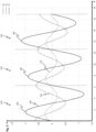
- Figure 3 a diagram with possible position-dependent curves 161, 162, 163 of a magnetic field strength for the magnetic field generated by the magnet arrangement 142 of the secondary part 140 along the direction of movement 170 and detectable by the sensor device 120 or by a magnetic field sensor 130. Shown in each case is the flux density B as a function of a position P relative to the direction of movement 170 for three magnet groups 150.
- a first curve 161 relates to the first magnetic field component Bx, a second curve 162 to the second magnetic field component By, and a third curve 163 to the third magnetic field component Bz.
- the three curves 161, 162, 163 have a substantially sinusoidal shape, with individual differences existing from one permanent pair to the next or from one magnet group 150 to the next.
- vertices 185 of the third curve 163 have different values of the flux density B. This can also apply to the first and second curves 161, 162.
- Such position-dependent differences in the magnetic field generated by the magnet arrangement 142 of the secondary part 140 and detectable by the sensor device 120 of the primary part 110 can be due to tolerances of the linear drive system 100 and its components. These can include mechanical and magnetic angular errors, magnetization errors, density differences, geometric deviations, adhesive gaps, mechanical misalignment, etc.
- the differences in the magnetic field are used in the linear drive system 100 to determine the position of the primary part 110 with respect to the secondary part 140. The following procedure is used here.
- the magnetic field of the magnet arrangement 142 is measured at different positions of the primary part 110 in relation to the secondary part 140 using the sensor device 120 is detected or sampled. Based on this, position-dependent reference magnetic field data is provided. This serves as the basis for the actual position determination carried out subsequently.
- the primary part 110 is located at an initially unknown current position relative to the secondary part 140.
- the current position can be a stationary position, so that at this position (initially) no movement is caused during operation of the linear drive system 100 and the primary part 110 is stationary.
- the magnetic field of the magnet arrangement 142 is again detected or sampled with the aid of the sensor device 120. Based on this, current magnetic field data is provided. Using the current magnetic field data and the reference magnetic field data, the current position of the primary part 110 is determined. As explained further below, this involves performing a similarity method.
- the initial measurement and position determination explained in more detail below can also be controlled or performed with the aid of the main control device 105 of the linear drive system 100 or with the participation of the main control device 105.
- the reference magnetic field data obtained by detecting the magnetic field of the magnet arrangement 142 with the aid of the sensor device 120, as well as the current magnetic field data, can be stored in the main control device 105.
- the current position of the primary part 110 can be determined with a high degree of reliability and accuracy based on this data.
- the following configuration is provided for the initial measurement for providing the reference magnetic field data.
- the initial measurement is performed in such a way that, with the aid of the magnetic field sensors 130 of the sensor device 120, the magnetic field is detected in the area of each individual magnet group 150 and corresponding magnetic field data is provided, which is thus assigned to the respective magnet groups 150.
- the magnetic field data obtained in this way and linked to the individual magnet groups 150 are referred to below as magnetic field patterns.
- the reference magnetic field data comprise all provided magnetic field patterns of the magnet groups 150.
- the magnetic field patterns which can be stored in the main control device 105, can also be referred to as reference patterns or templates.
- the initial measurement can comprise moving the primary part 110 along the secondary part 140 and providing the magnetic field patterns based on the magnetic field, which is detected with the aid of the magnetic field sensors 130 of the sensor device 120 whenever the magnetic field sensors 130 are located in the area of a magnet group 150, and insofar as, with respect to the direction of movement 170, there is coverage of the respective magnet group 150 by the magnetic field sensors 130.
- the magnetic field can be sampled during the movement of the primary part 110 at a predetermined sampling frequency using the magnetic field sensors 130, and corresponding magnetic field data can be generated based thereon. Of these, only those magnetic field data can be used and stored as magnetic field patterns which are provided based on the measured magnetic field when the magnetic field sensors 130 are, as stated above, located in the area of a magnet group 150 and cover it.
- Figure 4 a condition at a point in time, such as may be present during the initial measurement.
- the primary part 110 With respect to the primary part 110, only the sensor device 120 is shown, and with respect to the secondary part 140, only the magnet arrangement 142 is shown.
- This representation is also shown in subsequent figures (for example Figure 8 ) is selected.
- the following description is based on an exemplary embodiment of the sensor device 120 with forty-eight magnetic field sensors 130, which are distributed with respect to the direction of movement 170 and arranged at a distance from one another.
- Figure 4 (and also following figures) indices in the form of ".1", “.2", “.30”, “.48", “.n”, etc.
- the magnetic field sensors 130 which are identified by the reference numerals 130.1 and 130.48 and are located at opposite ends of the arrangement of magnetic field sensors 130, are hereinafter referred to as the first magnetic field sensor 130.1 and the forty-eighth magnetic field sensor 130.48.
- the magnet groups 150 of the magnet arrangement 142 are also provided with indices, whereby an arrangement comprising a first magnet group 150.1, a second magnet group 150.2, etc. up to an nth magnet group 150.n is present, where n can be, for example, 100.
- n can be, for example, 100.
- To the left of the first magnet group 150.1 can contain at least one further permanent magnet pair and thus at least one further magnet group 150 (not shown).
- the magnetic field patterns 210 of the reference magnetic field data 200 assigned to the individual magnet groups 150 are shown schematically and according to the positions of the magnet groups 150. These are also provided with indices, so that a first magnetic field pattern 210.1, a second magnetic field pattern 210.2, etc., up to an nth magnetic field pattern 210.n, is present.
- the sensor device 120 is located in the region of the second magnet group 150.2, so that the second magnet group 150.2 is covered by the magnetic field sensors 130.
- the magnetic field data obtained in this state by detecting the magnetic field with the aid of the magnetic field sensors 130 form the second magnetic field pattern 210.2 assigned to the second magnet group 150.2.
- the other magnetic field patterns 210 of the reference magnetic field data 200 are provided in a corresponding manner based on the magnetic field detected by the magnetic field sensors 130 if the sensor device 120 or its magnetic field sensors 130 are each located in the region of an associated magnet group 150 and cover it.
- performing the initial measurement further includes determining that the magnetic field sensors 130 of the sensor device 120 are each located in the area of a magnet group 150 and thus that there is an overlap of the magnet group 150, in order to carry out the above-described provision of the magnetic field patterns 210 of the magnet groups 150 based on or in accordance with this.
- Figure 4 such a boundary 190 between the first and second magnet group 150.1, 150.2 is illustrated by a dashed line.
- the boundaries 190 of adjacent permanent magnet pairs and magnet groups 150 can be represented by positive (i.e., with a positive gradient) zero crossings of a magnetic field strength curve of the third magnetic field component Bz obtained during the initial measurement along the direction of movement 170. Based on this, the Limits 190 are determined. To determine that the magnetic field sensors 130 are each located in the area of a magnet group 150, the course of the third magnetic field component Bz detected with the aid of an end-side magnetic field sensor 130 (which is located at one end of the arrangement of magnetic field sensors 130) can therefore be used.
- the first magnetic field sensor 130.1 can be used for this purpose.
- Figure 5 shows a diagram with curves 161, 162, 163 of the magnetic field strength relating to the different magnetic field components Bx, By, Bz, which can be obtained in the initial measurement by detecting the magnetic field with the aid of the first magnetic field sensor 130.1.
- a positive zero crossing 180 of the third curve 163 relating to the third magnetic field component Bz is indicated, by which a boundary 190 of adjacent permanent magnet pairs and magnet groups 150 is represented.
- the first magnetic field sensor 130.1 is located at or near a boundary 190 and thus a magnet group 150 is covered by the magnetic field sensors 130 of the sensor device 120, this can be determined based on a zero crossing 180 of the third magnetic field strength curve 163 of the third magnetic field component Bz, which was recorded with the aid of the first magnetic field sensor 130.1 during the initial measurement.
- the magnetic field data acquired at such a time with all magnetic field sensors 130 can form a corresponding magnetic field pattern 210 or be used as a magnetic field pattern 210.
- the provision of the magnetic field patterns 210 can thus be carried out on the basis of the magnetic field of the magnet arrangement 142 detected by the magnetic field sensors 130 in such a way that the presence of a zero crossing 180 in the third magnetic field component Bz measured by the first magnetic field sensor 130.1 is determined with the aid of the first magnetic field sensor 130.1.
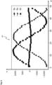
- Figure 6 shows a diagram with possible magnetic field data 205, which are generated by detecting the magnetic field with all magnetic field sensors 130 in the area of a magnet group 150, for example as in Figure 4 shown in the area of the second magnet group 150.2, and which are provided as magnetic field patterns 210 or corresponding Figure 4 can be treated and used as a second magnetic field pattern 210.2.
- the magnetic field data 205 shown include, with different symbols Data points, labeled in the form of circles, triangles, and squares, for the magnetic field components Bx, By, Bz detected by each magnetic field sensor 130 of the sensor device 120.
- a number M of a magnetic field sensor 130 for the sensor device 120 which according to the present example comprises forty-eight magnetic field sensors 130, is shown on the abscissa.
- the forty-eight magnetic field sensors 130 of the sensor device 120 are arranged next to one another along the direction of movement 170.
- the magnetic field data 205, and thus each magnetic field pattern 210 comprises forty-eight data points for each magnetic field component Bx, By, Bz.
- the forty-eighth magnetic field sensor 130.48 can also be used to detect boundaries 190 of adjacent magnet groups 150 based on the profile of the third magnetic field component Bz detected by this magnetic field sensor 130.48 in the initial measurement and thereby determine the times at which the magnetic field sensors 130 of the sensor device 120 are each located in the area of a magnet group 150.
- the provision of the magnetic field patterns 210 can also be coordinated with this.
- the actual position determination is performed in order to determine a current position of the primary part 110 on the secondary part 140. This can be carried out, for example, after a restart or after a power failure of the linear drive system 100.
- the position determination which, as stated above, can be carried out as part of a corresponding evaluation by the main control device 105, is carried out on the basis of the current magnetic field data obtained at the current position by detecting the magnetic field of the magnet arrangement 142 with the aid of the magnetic field sensors 130 of the sensor device 120 and the reference magnetic field data 200 previously provided as part of the initial measurement.
- the current magnetic field data are for the following description, in accordance with the Figure 7 , marked with the reference number 250.
- the current magnetic field data 250 comprises, corresponding to the magnetic field patterns 210 of the reference magnetic field data 200, data points for the magnetic field components Bx, By, Bz detected by each magnetic field sensor 130 of the sensor device 120, i.e., in this case, corresponding to the number of magnetic field sensors 130 per magnetic field component Bx, By, Bz, forty-eight data points.
- the diagram of Figure 6 also for the illustration of data obtained at a current position of the primary part 110 current magnetic field data 250.
- a similarity method is carried out for position determination using the current magnetic field data 250 and the magnetic field patterns 210 of the reference magnetic field data 200.
- the so-called DTW method Dynamic Time Warping
- the similarity of two data sets to be compared can be determined.
- the goal is to find an optimal match between the data sets when one of the data sets is mapped to the other in a distorted manner.
- a dynamic programming technique can be used for this purpose, in which each data point in one data set is compared with each data point in the other data set, thereby generating a distance matrix.
- This allows the most efficient path through the distance matrix to be determined, which represents an optimal mapping with the smallest overall distance between the data sets.
- the result can be a similarity measure in the form of the so-called DTW distance, which can represent the extent of the distortion for the optimal mapping. The smaller the DTW distance, the more similar the compared data sets are. This allows the similarity of the data sets to be assessed.
- the magnetic field sensors 130 of the sensor device 120 are located in the current position of the primary part 110 in the area of a magnet group 150 of the magnet arrangement 142 of the secondary part 140, whereby the respective magnet group 150, according to Figure 4 , which is covered by the magnetic field sensors 130.
- the current magnetic field data 250 can be compared with each of the magnetic field patterns 210 of the reference magnetic field data 200 using a DTW algorithm.
- a distance measure 270 can be obtained in the form of the above-mentioned DTW distance.
- Figure 7 Accordingly, by comparing the current magnetic field data 250 with the first magnetic field pattern 210.1, the second magnetic field pattern 210.2, ... the nth magnetic field pattern 210.n, a first distance measure 270.1, a second distance measure 270.2, ... an nth distance measure 270.n can be obtained.
- a magnetic field pattern 210 with the greatest similarity, i.e., with the smallest distance measure 270 or the smallest DTW distance is present, and thus the corresponding magnet group 150.
- This information represents the current position of the primary part 110 in relation to the secondary part 140.
- the sensor device 120 can also be offset in the area of two adjacent permanent magnet pairs and thus magnet groups 150 of the magnet arrangement 142 of the secondary part 140, whereby the two magnet groups 150 are each partially covered by the magnetic field sensors 130 of the sensor device 120 with respect to the direction of movement 170.
- the method variants explained below can be used, which are based on the approach explained previously. With regard to details regarding corresponding features and steps, reference is therefore made to the above description. Furthermore, features and details mentioned in relation to one method variant can also be applied to another method variant. The described steps can be carried out by evaluation with the aid of the main control device 105.
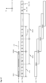
- Figure 8 shows a situation that can occur in the current position of the primary part 110.
- the sensor device 120 is arranged offset in the area of two adjacent magnet groups 150, in this case the first magnet group 150.1 and the second magnet group 150.2.
- the sensor device 120 is located above the boundary 190 of the two magnet groups 150.1, 150.2, and both magnet groups 150.1, 150.2 are each partially covered by the sensor device 120.
- both magnet groups 150.1, 150.2 therefore have an overlap area 230 related to the direction of movement 170, in which a sensor subgroup 240 comprising magnetic field sensors 130 of the sensor device 120 covers one of the magnet groups 150.1, 150.2.
- the first magnet group 150.1 has a first overlap area 230.1
- the second magnet group 150.2 has a second overlap area 230.2.
- Thirty magnetic field sensors 130 of the sensor device 120 are located in the first overlap area 230.1, i.e., the first magnetic field sensor 130.1 up to a thirtieth magnetic field sensor 130.30.
- the thirty magnetic field sensors 130 belonging to the first coverage area 230.1 represent a first sensor subgroup 240.1.
- a further eighteen magnetic field sensors 130 of the sensor device 120 are present, i.e. from a thirty-first (not shown) to the forty-eighth magnetic field sensor 130.48.
- the eighteen magnetic field sensors 130 belonging to the second coverage area 230.2 form a second sensor subgroup 240.2.
- a sensor position of the sensor device 120 with respect to a boundary 190 of two adjacent magnet groups 150 in the current position of the primary part 110 is provided.
- the position determination of the primary part 110 or the above-mentioned Figure 7 The comparison described above is carried out taking into account and coordinated with the determined sensor position.
- the sensor position is determined, similar to the provision of the magnetic field patterns 210 explained above, based on a positive zero crossing of the magnetic field strength curve of the third magnetic field component Bz, wherein the relevant curve is represented by the current magnetic field data 250 obtained with the aid of all magnetic field sensors 130.
- the zero crossing allows a boundary 190 of two adjacent permanent magnet pairs and magnet groups 150 to be detected, and thus the sensor position of the sensor device with respect to the boundary 190 can be detected.
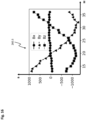
- Figure 9 a diagram of the current magnetic field data 250 is shown as shown in Figure 8 illustrated sensor position of the sensor device 120 by detecting the magnetic field of the magnet arrangement 142 with the aid of the magnetic field sensors 130.
- a curve 263 of the magnetic field strength of the third magnetic field component Bz, represented by the current magnetic field data 250 has a positive zero crossing 180, which coincides with the boundary 190 of two adjacent magnet groups 150 (according Figure 8 the first and second magnet groups 150.1, 150.2).
- the sensor position of the sensor device 120 with respect to the boundary 190, and thereby the offset positioning of the sensor device 120 over two adjacent magnet groups 150 can be detected and determined.
- the distance, relative to the direction of movement 170, between the relevant boundary 190 and the magnetic field sensors 130 of the sensor device 120 arranged closest to the boundary 190 can also be determined in the current position of the primary part 110.
- the magnetic field sensors 130 arranged closest to the boundary 190 and on both sides of the boundary 190 can first be identified based on the profile 263 of the third magnetic field component Bz represented by the current magnetic field data 250.
- the distance between the boundary 190 and the magnetic field sensors 130 located closest to the boundary 190 can be determined.
- the Figures 8 and 9 These are the thirtieth magnetic field sensor 130.30 and the thirty-first magnetic field sensor 130 (not shown), the thirtieth magnetic field sensor 130.30 having the smallest distance to the boundary 190 in the present case.
- the step can thus be carried out using a (known) uniform distance between the magnetic field sensors 130.
- a non-equidistant arrangement of the magnetic field sensors 130 can also be present, whereby the respective associated individual distance of the magnetic field sensors 130 can be used for the aforementioned step.
- Determining the distance between the magnetic field sensors 130 of the sensor device 120 relative to the direction of movement 170 can be carried out in the following manner. For this purpose, a total distance relative to the direction of movement 170 between the end-side magnetic field sensors 130 of the sensor device 120 (according to Figure 8 between the first and forty-eighth magnetic field sensors 130.1, 130.48). This can be done, for example, by measuring the sensor device 120. Furthermore, phase shifts of profiles of a magnetic field component of the magnetic field of the magnet arrangement 142 of the secondary part 140, which is detected with the aid of the magnetic field sensors 130, can be determined. This can be done as part of the initial measurement during the movement of the primary part 110 along the secondary part 140. The magnetic field component used can again be the third magnetic field component Bz.
- the distances of adjacent magnetic field sensors 130 relative to the direction of movement 170 can be determined on the basis of the total distance of the magnetic field sensors 130 and the phase shifts. Based on this or using the respectively associated distance (according to Figure 8 between the thirtieth magnetic field sensor 130.30 and the thirty-first magnetic field sensor 130), the distance between the boundary 190 and the magnetic field sensors 130 arranged closest to the boundary 190 can be determined.
- the sensor device 120 Based on the determined offset sensor position of the sensor device 120 with respect to a boundary 190 of two adjacent magnet groups 150, it can be further determined to what extent or ratio the sensor device 120 partially covers the respective magnet groups 150 in the current position of the primary part 110. From this, it can be deduced by which part of the magnetic field sensors 130 or by which sensor subgroup 240 the two magnet groups 150 are covered. In a corresponding manner, it can be determined which part of the current magnetic field data 250 relating to the individual magnet groups 150 was obtained using which sensor subgroup 240.
- the first sensor subgroup 240.1 which relates to the partial coverage of one of the two magnet groups 150 (in this case the first magnet group 150.1), and the second sensor subgroup 240.2, which relates to the partial coverage of the other of the two magnet groups 150 (in this case the second magnet group 150.2), can be determined.
- a partial data set of the current magnetic field data 250 is designated by reference numeral 260 for the following description, and partial patterns of the magnetic field patterns 210 are designated by reference numeral 220.
- a partial data set 260 is formed from the current magnetic field data 250, which was obtained with the aid of a sensor subgroup 240 comprising magnetic field sensors 130 of the sensor device 120, by means of which the partial coverage of one of the two magnet groups 150 is established.
- partial patterns 220 are formed from the magnetic field patterns 210 of the reference magnetic field data 200, which take into account the partial coverage of the relevant magnet group 150 caused by the sensor subgroup 240, and can thus reproduce or replicate the partial coverage with respect to each of the magnet groups 150 of the magnet arrangement 142 linked to the magnetic field patterns 210.
- the partial data set 260 of the current magnetic field data 250 is compared with the partial patterns 220 of the magnetic field patterns 210.
- a partial pattern 220 and consequently a magnetic field pattern 210 with the greatest similarity can be determined, thereby identifying the associated magnet group 150 and thus the positioning of the sensor device 120 on the respective magnet group 150.
- This information together with the detected sensor position of the sensor device 120 with respect to the boundary 190 of the adjacent magnet groups 150, represents the current position of the primary part 110.
- the adjacent magnet groups 150 are covered to different degrees by the sensor device 120, the formation of the partial data set 260, the partial patterns 220 and the comparison can be carried out with reference to the larger partial coverage and larger sensor subgroup 240 from magnetic field sensors 130.
- the larger partial coverage of one of two adjacent magnet groups 150 by the first sensor subgroup 240.1 (covering the first magnet group 150.1 in this case) occurs in the direction of movement 170. This can be determined based on the determined sensor position.
- a corresponding first partial data set 260.1 can therefore be formed from those data or data points of the current magnetic field data 250 which were obtained by detecting the magnetic field of the magnet arrangement 142 with the aid of the magnetic field sensors 130 of the first sensor subgroup 240.1 (with the first magnetic field sensor 130.1 up to the thirtieth magnetic field sensor 130.30).
- the first partial data set 260.1 refers to the data points located to the left of the zero crossing 180 and thus the limit 190.
- the first partial data set 260.1 is shown separately in a separate diagram.
- the first partial data set 260.1 comprises, corresponding to the thirty magnetic field sensors 130 of the first sensor subgroup 240.1, thirty data points per magnetic field component Bx, By, Bz.
- the partial patterns 220 provided for comparison with the first partial data set 260.1 can be formed from the magnetic field patterns 210 of the reference magnetic field data 200, wherein this is coordinated with the determined partial coverage of a magnet group 150 by the first sensor subgroup 240.1.
- Figure 8 the formation of the first partial patterns 220.1 relating to the partial coverage by the first sensor subgroup 240.1 from the magnetic field patterns 210 is schematically indicated.
- a corresponding first partial pattern 220.1 is formed for each magnetic field pattern 210.
- the first partial patterns 220.1 simulate the partial coverage caused by the first sensor subgroup 240.1 with respect to each of the magnet groups 150 of the magnet arrangement 142 linked to the magnetic field patterns 210.
- the first partial patterns 220.1 each comprise the last thirty data points of the magnetic field patterns 210 (not shown) for each magnetic field component Bx, By, Bz.
- the first partial data set 260.1 of the current magnetic field data 250 is compared with each first partial pattern 220.1 of the magnetic field patterns 210 (i.e., the first partial pattern 220.1 of the first magnetic field pattern 210.1, the first partial pattern 220.1 of the second magnetic field pattern 210.2, ... the first partial pattern 220.1 of the nth magnetic field pattern 210.n) in order to obtain a corresponding distance measure 270 (i.e., a first distance measure 270.1, a second distance measure 270.2, ... an nth distance measure 270.n).
- a corresponding distance measure 270 i.e., a first distance measure 270.1, a second distance measure 270.2, ... an nth distance measure 270.n.
- this information reflects the current position of the primary part 110 on the secondary part 140.
- a corresponding second partial data set 260.2 can be formed from the data points of the current magnetic field data 250, which were obtained by detecting the magnetic field of the magnet arrangement 142 with the aid of the magnetic field sensors 130 of the second sensor subgroup 240.2 (with the thirty-first to forty-eighth magnetic field sensors 130.48, not shown).
- the second partial data set 260.2 comprises the data points located to the right of the zero crossing 180 and thus the boundary 190, the number of which, corresponding to the second sensor subgroup 240.2, is eighteen per magnetic field component Bx, By, Bz.
- second partial patterns 220.2 can be formed from the magnetic field patterns 210, which replicate the partial coverage caused by the second sensor subgroup 240.2 with respect to each of the magnet groups 150 of the magnet arrangement 142 linked to the magnetic field patterns 210, as shown in Figure 8 is indicated schematically.
- the second subpatterns 220.2 each comprise the first eighteen data points of the magnetic field patterns 210 (not shown) for each magnetic field component Bx, By, Bz.
- the second partial data set 260.2 of the current magnetic field data 250 is compared with every second partial pattern 220.2 of the magnetic field patterns 210 in order to obtain a corresponding distance measure 270.
- the second partial pattern 220.2 and the corresponding magnetic field pattern 210 with the greatest similarity can be determined, and thereby the positioning of the sensor device 120 on the associated magnet group 150 (i.e. the second magnet group 150.2 in Figure 8 ) can be determined.
- this information represents the current position of the primary part 110 on the secondary part 140.
- the comparison can be carried out using a partial data set 260 of the current magnetic field data 250 and partial patterns 220 of the magnetic field patterns 210 with respect to one of the two partial coverages.
- a partial data set 260 and corresponding partial patterns 220 for each of the two partial coverages, and to compare the respective partial data set 260 with the associated partial patterns 220.
- a corresponding partial pattern 220 and a magnetic field pattern 210 with the greatest similarity, and thus an associated magnet group 150 can be determined.
- a plausibility check can also be implemented.
- the determined partial patterns 220 with the greatest similarity it is required that they belong to two adjacent magnet groups 150. If this is not the case, the presence of an error, for example in the form of faulty data, can be concluded based on this plausibility check.
- the first partial data set 260.1 can be compared with each of the first partial patterns 220.1, and the second partial data set 260.2 can be compared with each of the second partial patterns 220.2. Based on the comparison or the greatest similarity determined, a corresponding magnet group 150 can be determined. For the Figure 8 In the sensor position shown, this should be the first and second magnet group 150.1, 150.2. If this is not the case, and for example, in the comparison carried out with the first partial data set 260.1, the first magnet group 150.1, and in the case of If the comparison carried out with the second partial data set 260.2 determines another magnet group 150 instead of the second magnet group 150.2, an error can be detected.
- the magnetic field sensors 130 of the sensor device 120 are located in the current position of the primary part 110 in the area of a magnet group 150 of the magnet arrangement 142 of the secondary part 140 and thus, for example, a situation exists as shown in Figure 4
- such positioning can also be detected by determining the sensor position of the sensor device 120 with respect to a boundary 190 of two adjacent permanent magnet pairs or magnet groups 150.
- the boundary 190 in question can be present in the region of an edge or end of the sensor device 120.
- Such a sensor position can be determined based on the presence of a positive zero crossing in a magnetic field strength curve of the third magnetic field component Bz, which coincides with the boundary 190 and can be reproduced by the current magnetic field data 250 obtained with the aid of all magnetic field sensors 130. If there is no positive zero crossing in the magnetic field strength curve or in the area of the ends of the magnetic field strength curve, it can be recognized that the magnetic field sensors 130 of the sensor device 120 are located in the current position of the primary part 110 in the area of a magnet group 150 and that the respective magnet group 150 is covered by the magnetic field sensors 130.
- the magnetic field sensors 130 can be adjusted accordingly and, as described above with reference to Figure 7
- the current magnetic field data 250 are compared with the magnetic field patterns 210 of the reference magnetic field data 200 in order to determine a magnetic field pattern 210 with the greatest similarity, and thus the associated magnet group 150 and, to that extent, the positioning of the sensor device 120 on the relevant magnet group 150.
- the distance, related to the direction of movement 170, between a boundary 190 and a magnetic field sensor 130 arranged closest to the boundary 190 can also be determined.
- the relevant distance can be determined by performing an extrapolation using the magnetic field strength curve of the third magnetic field component represented by the current magnetic field data 250 Bz can be determined.
- This distance information relating to the sensor position, together with the determined positioning of the sensor device 120 on a magnet group 150, can reflect the current position of the primary part 110 on the secondary part 140.
- newly composed magnetic field patterns are formed, each of which is composed of partial patterns 220 of magnetic field patterns 210 of two adjacent magnet groups 150 provided during the initial measurement, taking into account the partial overlaps.
- the newly composed magnetic field patterns can reproduce or replicate the positioning of the sensor device 120 determined based on the sensor position and thus the overlap achieved by the sensor device 120 with respect to two adjacent magnet groups 150 of the magnet arrangement 142.
- the current magnetic field data 250 are compared with the composed magnetic field patterns. In this way, a composed magnetic field pattern with the greatest similarity, thereby the two magnet groups 150 belonging to the composed magnetic field pattern, and thus the positioning of the sensor device 120 at the relevant two magnet groups 150, can be determined.
- This information together with the detected sensor position of the sensor device 120 with respect to the boundary 190 of the adjacent magnet groups 150, represents the current position of the primary part 110.
- Figure 11 a further illustration in which the sensor device 120 according to Figure 8 is arranged offset in the region of two adjacent magnet groups 150, or the first and second magnet groups 150.1, 150.2.
- the first magnet group 150.1 is covered, relative to the direction of movement 170, by the first sensor subgroup 240.1 comprising thirty magnetic field sensors 130.
- the second magnet group 150.2 is covered, relative to the direction of movement 170, by the second sensor subgroup 240.2 comprising eighteen magnetic field sensors 130.
- Figure 11 further schematically illustrates the formation of newly composed magnetic field patterns 225, which emulate the coverage achieved by the sensor device 120 with respect to two adjacent magnet groups 150 of the magnet arrangement 142 and their magnetic field pattern 210.
- the composed magnetic field patterns 225 each comprise a first partial pattern 220.1 of a magnetic field pattern 210 of a magnet group 150 and a second partial pattern 220.2 of a magnetic field pattern 210 of an adjacent magnet group 150.
- the partial coverage achieved by the first sensor subgroup 240.1 is reproduced with respect to a magnet group 150 via a first partial pattern 220.1
- the partial coverage achieved by the second sensor subgroup 240.2 is reproduced with respect to an adjacent magnet group 150 via a second partial pattern 220.2.
- one of the composite magnetic field patterns 225 is formed using a first partial pattern 220.1 of the first magnetic field pattern 210.1 and a second partial pattern 220.2 of the second magnetic field pattern 210.2.
- another composite magnetic field pattern 225 is formed using a first partial pattern 220.1 of the second magnetic field pattern 210.2 and a second partial pattern 220.2 of a third magnetic field pattern 210 (not shown).
- the formation of further composite magnetic field patterns 225 can be continued in an analogous manner up to the nth magnetic field pattern 210.n.
- the first subpatterns 220.1 each comprise the last thirty data points of the magnetic field patterns 210 for each magnetic field component Bx, By, Bz.
- the second subpatterns 220.2 each comprise the first eighteen data points of the magnetic field patterns 210 for each magnetic field component Bx, By, Bz.
- the combined magnetic field patterns 225 thus comprise, in accordance with the current magnetic field data 250, forty-eight data points for each magnetic field component Bx, By, Bz (not shown in each case).
- the current magnetic field data 250 are compared with each of the composite magnetic field patterns 225 in order to to obtain a corresponding distance measurement 270 in each case.
- This allows a composite magnetic field pattern 225 with the greatest similarity, i.e., one with the smallest distance measurement 270, and consequently the positioning of the sensor device 120 on the associated two magnet groups 150 to be determined.
- this information represents the current position of the primary part 110 on the secondary part 140.
- the position determination can further be carried out as follows.
- a predetermined division of the magnetic field sensors 130 of the sensor device 120 into several (i.e., at least two) sensor subgroups 240 is used as a basis.
- the division is independent of the sensor position of the sensor device 120 present in the current position of the primary part 110.
- the division can be carried out such that the sensor subgroups 240 each comprise the same number of magnetic field sensors 130.
- the current magnetic field data 250 is divided into several (i.e., at least two) partial data sets 260, which were obtained from magnetic field sensors 130 with the aid of the individual sensor subgroups 240, each of which partially covers the magnet arrangement 142.
- partial patterns 220 are formed from the magnetic field patterns 210 of the reference magnetic field data 200, which takes into account the detected sensor position of the sensor device 120 in the current position of the primary part 110 as well as the distribution of the magnetic field sensors 130 and thus the partial overlaps caused by the sensor subgroups 240.
- the detection of the sensor position in which the position of the sensor device 120 is determined with respect to a boundary 190 of adjacent magnet groups 150, can be carried out, as described above, based on a positive zero crossing of the magnetic field strength curve of the third magnetic field component Bz, which is represented by the current magnetic field data 250.
- the partial patterns 220 used in this method variant can reproduce or simulate the partial overlaps caused by the individual sensor subgroups 240 with respect to two adjacent magnet groups 150 of the magnet arrangement 142.
- those subpatterns 220 that represent the partial overlap caused by this sensor subgroup 240 can be formed, similar to the previously explained method variant, by assembling corresponding parts of magnetic field patterns 210 from adjacent magnet groups 150.
- the subpatterns 220 relating to the partial overlaps of these sensor subgroups 240 can be assembled by parts of magnetic field patterns 210 from adjacent magnet groups 150.
- the partial data sets 260 are compared with the respective subpatterns 220 with respect to the sensor position of the sensor device 120 and the distribution of the magnetic field sensors 130, and thus the partial overlaps caused by the sensor subgroups 240.
- the subpatterns 220 with the greatest similarity thereby the two magnet groups 150 belonging to the subpatterns 220, and thus the positioning of the sensor device 120 on the respective two magnet groups 150, can be determined.
- This information together with the detected sensor position of the sensor device 120 with respect to the boundary 190 of the adjacent magnet groups 150, reflects the current position of the primary part 110.
- Figure 12 Another illustration in which the sensor device 120 is arranged in the current position of the primary part 110, offset in the region of two adjacent magnet groups 150, in this case again the first and second magnet groups 150.1, 150.2.
- the first magnet group 150.1 is covered by thirty magnetic field sensors 130 (with the first magnetic field sensor 130.1 up to the thirtieth magnetic field sensor 130.30)
- the second magnet group 150.2 is covered by eighteen magnetic field sensors 130 (with the thirty-first magnetic field sensor 130 (not shown) up to the forty-eighth magnetic field sensor 130.48) of the sensor device 120.
- a predetermined division of the magnetic field sensors 130 of the sensor device 120 into several sensor subgroups 240 is used, independently of this.
- Figure 12 In the procedure illustrated, a division into two sensor subgroups 240, ie a first and a second sensor subgroup 240.1, 240.2, each having twenty-four magnetic field sensors 130, is provided.
- the first sensor subgroup 240.1 comprises the first Magnetic field sensor 130.1 up to a twenty-fourth magnetic field sensor 130 (not shown), and the second sensor subgroup 240.2 comprises a twenty-fifth magnetic field sensor 130 (not shown) up to the forty-eighth magnetic field sensor 130.48 of the sensor device 120.
- the two sensor subgroups 240.1, 240.2 each cover a different part of the magnet arrangement 142 or of the adjacent magnet groups 150.1, 150.2. This includes a first coverage area 230.1 relating to the partial coverage by the first sensor subgroup 240.1 and a second coverage area 230.2 relating to the partial coverage by the second sensor subgroup 240.2.
- the current magnetic field data 250 is converted into a first partial data set 260.1 and a second partial data set 260.2, wherein the first partial data set 260.1 was obtained by detecting the magnetic field of the magnet arrangement 142 with the aid of the first sensor subgroup 240.1 and the second partial data set 260.2 was obtained by detecting the magnetic field of the magnet arrangement 142 with the aid of the second sensor subgroup 240.2.
- the two partial data sets 260.1, 260.2 have, corresponding to the twenty-four magnetic field sensors 130 per sensor subgroup 240.1, 240.2, twenty-four data points per magnetic field component Bx, By, Bz.
- the partial data sets 260.1, 260.2 can comprise data points, as shown in the diagrams of Figures 13 and 14 is illustrated.
- Figure 12 further schematically illustrates the formation of partial patterns 220 from the magnetic field patterns 210 of the reference magnetic field data 200, which is carried out both in a manner coordinated with the detected sensor position of the sensor device 120 with respect to the boundary 190 and in a manner coordinated with the partial overlaps achieved by the sensor subgroups 240.1, 240.2.
- First and second partial patterns 220.1, 220.2 are formed, which respectively replicate the partial overlaps achieved by the first and second sensor subgroups 240.1, 240.2 with respect to two adjacent magnet groups 150 of the magnet arrangement 142 and their magnetic field patterns 210.
- the first subpatterns 220.1 each comprise twenty-four data points of the magnetic field patterns 210 linked to the magnet groups 150 for each magnetic field component Bx, By, Bz. These are by a nineteenth to a forty-second data point of the magnetic field patterns 210 (not shown).
- the second partial patterns 220.2 each comprise twenty-four data points per magnetic field component Bx, By, Bz. Due to the fact that in the second sensor subgroup 240.2, as in Figure 12 shown, there is an overlap of the boundary 190, which can be recognized by the sensor position, the associated second partial patterns 220.2, which reflect the partial overlap caused by the second sensor subgroup 240.2, are composed of parts of magnetic field patterns 210 of adjacent magnet groups 150 that are matched to this.
- the second partial patterns 220.2 therefore comprise six data points per magnetic field component Bx, By, Bz, which are the last six data points of magnetic field patterns 210 linked to the magnet groups 150, and a further eighteen data points, which are the first eighteen data points of magnetic field patterns 210 of adjacent (and corresponding Figure 12 (located to the right of each) magnet groups 150 (not shown).
- first and second partial pattern 220.1, 220.2 is shown only with respect to the first magnetic field pattern 210.1 and the second magnetic field pattern 210.2 of the reference magnetic field data 200. Similarly, further first and second partial patterns 220.1, 220.2 are formed with respect to the second magnetic field pattern 210.2, and a third magnetic field pattern 210 is formed with respect to the third and a fourth magnetic field pattern 210, etc., up to an nth magnetic field pattern (not shown).
- the partial data sets 260.1, 260.2 of the current magnetic field data 250 are compared with the respective partial patterns 220.1, 220.2 associated with the sensor position of the sensor device 120 and the partial overlaps caused by the sensor subgroups 240.1, 240.2 in order to obtain a corresponding distance measure 270.
- the first partial data set 260.1 can be compared with each of the associated first partial patterns 220.1
- the second partial data set 260.2 can be compared with each of the associated second partial patterns 220.2.
- a first and second partial pattern 220.1, 220.2 with the greatest similarity, i.e., for which the smallest distance measure 270 is present, can be determined. Accordingly, those two adjacent Magnet groups 150, and thereby a positioning of the sensor device 120 can be determined on those adjacent magnet groups 150 that belong to the determined partial patterns 220.1, 220.2.
- this information reflects the current position of the primary part 110 on the secondary part 140.
- a plausibility check can also be performed. This requires that two adjacent magnet groups 150 are identified in a consistent manner based on the determined partial patterns 220 with the greatest similarity. If this is not the case, the presence of an error, for example in the form of erroneous data, can be assumed. Figure 12 Such an error can, for example, be noticeable in that the first magnet group 150.1 is identified in the first evaluation 281, and other magnet groups 150 are determined in the second evaluation 282 instead of the first and second magnet groups 150.1, 150.2.
- Figure 15 Another representation of the sensor device 120, which is arranged offset in the current position of the primary part 110 in the region of two adjacent magnet groups 150, or the first and second magnet groups 150.1, 150.2.
- the first magnet group 150.1 is covered by thirty magnetic field sensors 130
- the second magnet group 150.2 is covered by eighteen magnetic field sensors 130 of the sensor device 120.
- the magnetic field sensors 130 can be divided into four sensor subgroups 240, i.e., a fourth, fifth, sixth, and seventh sensor subgroup 240.4, 240.5, 240.6, 240.7, each comprising twelve magnetic field sensors 130.
- the current magnetic field data 250 can be divided into four subdata sets 260, i.e., a fourth, fifth, sixth, and seventh subdata set 260.4, 260.5, 260.6, 260.7, each comprising twelve data points for each magnetic field component Bx, By, Bz.
- partial patterns 220 can be formed from the magnetic field patterns 210 of the reference magnetic field data 200, which partial patterns 220 represent the magnetic field patterns realized by the sensor subgroups 240.4, 240.5, 240.6, 240.7. Partial overlaps are simulated in each case with respect to two adjacent magnet groups 150 of the magnet arrangement 142 and their magnetic field pattern 210, and which comprise twelve data points per magnetic field component Bx, By, Bz (not shown in each case).
- the similarity comparison in which the partial data sets 260.4, 260.5, 260.6, 260.7 of the current magnetic field data 250 are compared with the respective subpatterns 220 with regard to the sensor position and the distribution of the magnetic field sensors 130 among the sensor subgroups 240.4, 240.5, 240.6, 240.7, four subpatterns 220 with the greatest similarity, thus the associated two magnet groups 150, and thereby the positioning of the sensor device 120 on the respective two magnet groups 150, can be determined.
- This information together with the sensor position of the sensor device 120, represents the current position of the primary part 110 on the secondary part 140. If different neighboring magnet groups 150 are determined in this process, it can be concluded that an error is present.
- Figure 15 further illustrates a further variant in which the magnetic field sensors 130 of the sensor device are divided into three partially overlapping sensor subgroups 240, ie a first, second and third sensor subgroup 240.1, 240.2, 240.3, each comprising twenty-four magnetic field sensors 130.
- the first and second sensor subgroups 240.1, 240.2 correspond to the sensor subgroups 240 of Figure 12
- the third sensor subgroup 240.3 overlaps with the other two sensor subgroups 240.1, 240.2 and is composed of half of the magnetic field sensors 130 from the other two sensor subgroups 240.1, 240.2.
- the three sensor subgroups 240.1, 240.2, 240.3 each cover a different part of the magnet arrangement 142 or the adjacent magnet groups 150.1, 150.2.
- the current magnetic field data 250 is divided into three overlapping partial data sets 260, ie a first, second and third partial data set 260.1, 260.2, 260.3, each of which was obtained by detecting the magnetic field of the magnet arrangement 142 with the aid of one of the three sensor subgroups 240.1, 240.2, 240.3.
- the three partial data sets 260.1, 260.2, 260.3 have, corresponding to the twenty-four magnetic field sensors 130 each sensor subgroup 240.1, 240.2, 240.3, twenty-four data points per magnetic field component Bx, By, Bz.
- the first and second subdata sets 260.1, 260.2 may include data points as shown in the diagrams of Figures 13 and 14 With reference to the data points of the third subdata set 260.3, the diagram of Figure 16 come into play.
- the first, second and third sensor subgroups 240.1, 240.2, 240.3 can be derived based on the previously explained division with the four sensor subgroups 240.4, 240.5, 240.6, 240.7, in that the first sensor subgroup 240.1 comprises the fourth and fifth sensor subgroups 240.4, 240.5, the second sensor subgroup 240.2 comprises the sixth and seventh sensor subgroups 240.6, 240.7, and the third sensor subgroup 240.3 comprises the fifth and sixth sensor subgroups 240.5, 240.6.
- the first, second and third partial data sets 260.1, 260.2, 260.3 can be formed by using the four partial data sets 260.4, 260.5, 260.6, 260.7, wherein the first partial data set 260.1 comprises the fourth and fifth partial data sets 260.4, 260.5, the second partial data set 260.2 comprises the sixth and seventh partial data sets 260.6, 260.7, and the third partial data set 260.3 comprises the fifth and sixth partial data sets 260.5, 260.6.
- FIG. 15 Furthermore, a schematic representation of the formation of partial patterns 220 from the magnetic field patterns 210 of the reference magnetic field data 200 is shown, which takes into account the sensor position of the sensor device 120 with respect to the boundary 190 and the partial overlaps achieved by the three sensor subgroups 240.1, 240.2, 240.3.
- First, second, and third partial patterns 220.1, 220.2, 220.3 are formed, which each represent the partial overlaps achieved by the three sensor subgroups 240.1, 240.2, 240.3 with respect to two adjacent magnet groups 150 of the magnet arrangement 142 and their magnetic field patterns 210.
- the first subpatterns 220.1 each comprise twenty-four data points per magnetic field component Bx, By, Bz, i.e. a nineteenth to a forty-second data point, of the magnetic field patterns 210 of the magnet groups 150 (not shown).
- the second subpatterns 220.2 comprise per magnetic field component Bx, By, Bz each have twenty-four data points.
- the second sensor subgroup 240.2 covers, as shown in Figure 15 shown, the boundary 190, which can be recognized based on the sensor position.
- the second partial patterns 220.2 which represent the partial coverage caused by the second sensor subgroup 240.2, are composed of parts of magnetic field patterns 210 of adjacent magnet groups 150 that are matched thereto.
- the second partial patterns 220.2 therefore comprise, for each magnetic field component Bx, By, Bz, six first data points, which are the last six data points of magnetic field patterns 210 of magnet groups 150, and a further eighteen data points, which are the first eighteen data points of magnetic field patterns 210 of adjacent (and correspondingly Figure 15 (located to the right of each) magnet groups 150 (not shown).
- the third subpatterns 220.3 each comprise twenty-four data points per magnetic field component Bx, By, Bz. Due to the fact that also in the third sensor subgroup 240.3, as in Figure 15 shown, there is an overlap of the boundary 190, which can be recognized by the sensor position, the third partial patterns 220.3, which represent the partial overlap caused by the third sensor subgroup 240.3, are composed of parts of magnetic field patterns 210 of adjacent magnet groups 150 that are matched to this.
- the third partial patterns 220.3 therefore comprise eighteen data points per magnetic field component Bx, By, Bz, which are the last eighteen data points of magnetic field patterns 210 of magnet groups 150, and a further six data points, which are the first six data points of magnetic field patterns 210 of adjacent (and corresponding Figure 15 (located to the right of each) magnet groups 150 (not shown).
- first, second, and third partial pattern 220.1, 220.2, 220.3 is shown only with respect to the first magnetic field pattern 210.1 and the second magnetic field pattern 210.2 of the reference magnetic field data 200.
- further first, second, and third partial patterns 220.1, 220.2, 220.3 are formed with respect to the second magnetic field pattern 210.2, and a third magnetic field pattern 210 is formed with respect to the third and a fourth magnetic field pattern 210, etc., up to an nth magnetic field pattern (not shown).
- the partial data sets 260.1, 260.2, 260.3 of the current magnetic field data 250 are compared with the respective partial patterns 220.1, 220.2, 220.3 with respect to the sensor position of the sensor device 120 and the distribution of the magnetic field sensors 130 to the sensor subgroups 240.1, 240.2, 240.3 in order to obtain a corresponding distance measure 270.
- the first partial data set 260.1 can be compared with each of the associated first partial patterns 220.1, in the context of a second evaluation 282, the second partial data set 260.2 can be compared with each of the associated second partial patterns 220.2, and in the context of a third evaluation 283, the third partial data set 260.3 can be compared with each of the associated third partial patterns 220.3.
- three partial patterns 220.1, 220.2, 220.3 with the greatest similarity, and thus the associated two magnet groups 150, and thereby the positioning of the sensor device 120 on the relevant two magnet groups 150 (in this case, the magnet groups 150.1, 150.2) can be determined.
- This information together with the sensor position of the sensor device 120, indicates the current position of the primary part 110 on the secondary part 140. If different adjacent magnet groups 150 are detected, the presence of an error can be detected.
- the position of the primary part 110 in relation to the secondary part 140 can be determined with high reliability and accuracy.
- the sensor device 120 whose magnetic field sensors 130, as stated above, can cover a magnet group 150 comprising a pair of two permanent magnets 155 or a first and second permanent magnet 151, 152, can therefore have a different or larger number of magnetic field sensors 130, which are arranged along distributed along the direction of movement 170 and spaced apart from one another on the circuit board 121 of the sensor device 120. For example, seventy-two or more magnetic field sensors 130 are possible. This can enhance the accuracy and reliability of position determination. This can be noticeable, for example, with regard to a design of the magnet arrangement 142 of the secondary part 140 with a relatively large number of permanent magnets 155 and permanent magnet pairs.
- the maximum possible number of magnetic field sensors 130 may be limited by mutual interference between the magnetic field sensors 130, which can occur when the magnetic field sensors 130 are relatively close together.
- the magnetic field sensors 130 can also be spaced apart from one another in such a way that interference between the magnetic field sensors 130 can be avoided.
- the position determination can be carried out on the basis of magnet groups 150, which do not comprise a single permanent magnet pair, but rather, coordinated with the sensor device 120 and corresponding to the possible overlap by the magnetic field sensors 130, a plurality of permanent magnet pairs each consisting of a first and a second permanent magnet 151, 152.
- the distribution of the permanent magnets 155 among the magnet groups 150 can also be implemented such that the magnet groups 150 partially overlap.
- the sensor device 120 in the current position of the primary part 110 and in the presence of an offset sensor position, to cover a plurality of boundaries 190 of adjacent permanent magnet pairs or magnet groups 150, which can be detected based on positive zero crossings of a magnetic field strength curve of the third magnetic field component Bz represented by the current magnetic field data 250.
- the evaluation for position determination can be carried out with respect to one of the boundaries 190, coordinated with this.
- Figure 17 shows a further possible embodiment that can be considered for the sensor device 120 of the primary part 110.
- the sensor device 120 has ninety-six magnetic field sensors 130, i.e., from a first magnetic field sensor 130.1 to a ninety-sixth magnetic field sensor 130.96, which are distributed along the direction of movement 170 and arranged at a distance from one another.
- the sensor device 120 is designed such that, with the aid of the magnetic field sensors 130, a complete or essentially complete coverage of two permanent magnet pairs, each consisting of a first and a second permanent magnet 151, 152, can be achieved.
- the magnet groups 150 also have two permanent magnet pairs each consisting of a first and a second permanent magnet 151, 152, and thus a total of four permanent magnets 155.
- the first magnet group 150.1 therefore comprises a first and second permanent magnet pair
- the second magnet group 150.2 comprises the second and a third permanent magnet pair
- the third magnet group 150.3 comprises the third and a fourth permanent magnet pair, etc.
- This division also has the consequence that, in the evaluation carried out for the purpose of position determination with the aid of the main control device 105, two adjacent magnet groups 150 or, in other words, the magnet groups 150 located on either side of a boundary 190, and thus two magnet groups 150 with either an odd-numbered or an even-numbered index, are to be regarded as adjacent magnet groups 150.
- the first and third magnet groups 150.1, 150.3 represent two adjacent magnet groups 150. This applies correspondingly to the second and fourth magnet groups 150.2, 150.4.
- the first magnet group 150.1 cannot be a magnet group 150 located at a (left) end of the magnet arrangement 142, and can only be considered as the first magnet group 150.1 for the following description.
- To the left of the first magnet group 150.1 there can be at least one further permanent magnet pair. Consequently, from the second magnet group 150.2, a further magnet group 150 may be present which is adjacent to the second magnet group 150.2 (not shown).
- Figure 17 further illustrates the magnetic field patterns 210 of the reference magnetic field data 200 assigned to the individual magnet groups 150, which partially overlap according to the magnet groups 150.
- the magnetic field patterns 210 can also be obtained in the initial measurement analogously to the procedure explained above.
- the primary part 110 can be moved along the secondary part 140, and the magnetic field patterns 210 can be provided based on the magnetic field, which is detected with the aid of the magnetic field sensors 130 of the sensor device 120 whenever the magnetic field sensors 130 are located in the area of a magnet group 150, and thus there is an overlap of the respective magnet group 150 by the magnetic field sensors 130.
- the provision of the magnetic field patterns 210 can be coordinated with positive zero crossings of a magnetic field strength profile of the third magnetic field component Bz detected by means of an end-side magnetic field sensor 130, for example the first magnetic field sensor 130.1, during the movement of the primary part 110, via which boundaries 190 of adjacent permanent magnet pairs and magnet groups 150 can be reproduced (cf. Figure 18 ).
- the current magnetic field data 250 obtained by detecting the magnetic field of the magnet arrangement 142 of the secondary part 140 with the aid of the magnetic field sensors 130 at the current position of the primary part can have ninety-six data points per magnetic field component Bx, By, Bz. This also applies to the magnetic field patterns 210 (not shown) provided during the initial measurement.
- the steps and method variants explained above can be applied accordingly.
- the magnetic field sensors 130 of the sensor device 120 are located in the current position of the primary part 110 in the area of a magnet group 150 of the magnet arrangement 142 of the secondary part 140, whereby the respective magnet group 150 is covered by the magnetic field sensors 130 and a situation comparable to Figure 17
- Such positioning can be detected by determining the sensor position of the sensor device 120 with respect to a boundary 190 of two adjacent permanent magnet pairs or magnet groups 150.
- the boundary 190 in question can be located in the region of an edge or end of the sensor device 120.
- Such a sensor position can be determined based on the presence of a positive Zero crossing in a magnetic field strength curve of the third magnetic field component Bz can be determined, which can be reproduced by the current magnetic field data 250 obtained with the aid of all magnetic field sensors 130 at the current position.
- the magnetic field sensors 130 of the sensor device 120 are located in the current position of the primary part 110 in the area of a magnet group 150 and that the respective magnet group 150 is covered by the magnetic field sensors 130.
- the current magnetic field data 250 are compared with the magnetic field patterns 210 of the reference magnetic field data 200 in order to determine a magnetic field pattern 210 with the greatest similarity, thereby the associated magnet group 150, and thus the positioning of the sensor device 120 at the relevant magnet group 150.
- the distance, related to the direction of movement 170, between a boundary 190 and a magnetic field sensor 130 arranged closest to the boundary 190, for example, the first magnetic field sensor 130.1, can also be determined. This can be done by means of extrapolation using the magnetic field strength curve of the third magnetic field component Bz represented by the current magnetic field data 250.
- the sensor device 120 can also be offset in the area of two adjacent (adjacent) magnet groups 150, as shown in Figure 18 Due to the overlapping magnet groups 150, the offset arrangement of the sensor device 120 can refer to two pairs of adjacent magnet groups 150. According to the illustration in Figure 18 This applies to the first and the adjacent third magnet group 150.1, 150.3. If, as indicated above, there is another permanent magnet pair to the left of the first magnet group 150.1 and, to that extent, there is another magnet group 150 to the left of and adjacent to the second magnet group 150.2, the offset arrangement of the sensor device 120 also applies to this additional magnet group 150 and the second magnet group 150.2. Due to the offset arrangement, the respective adjacent magnet groups 150 are each partially covered by the magnetic field sensors 130 of the sensor device 120.
- the sensor device 120 can cover two pairs of permanent magnets (cf. Figure 17 ), the sensor device 120 can be offset Positioning furthermore over two boundaries 190 of adjacent permanent magnet pairs or magnet groups 150, as in Figure 18 is illustrated by a first boundary 190.1 and a second boundary 190.2.
- the two boundaries 190.1, 190.2 can also be detected based on the current magnetic field data 250 obtained at the current position of the primary part 110 with the aid of the magnetic field sensors 130.
- the boundaries 190.1, 190.2 coincide with positive zero crossings of the magnetic field strength curve of the third magnetic field component Bz represented by the current magnetic field data 250, and can therefore be detected based on the zero crossings.
- one of the two boundaries 190 can be selected and used.
- the Figure 18 The second boundary 190.2, located to the right with respect to the direction of movement 170, is selected.
- the further evaluation is carried out using the selected boundary 190.
- the distance, relative to the direction of movement 170, between the selected boundary 190 and the magnetic field sensors 130 of the sensor device 120 arranged closest to and on both sides of the boundary 190 can be determined, as described above. This can be done using the magnetic field strength curve of the third magnetic field component Bz represented by the current magnetic field data 250, by identifying the magnetic field sensors 130 located closest to the boundary 190, and by performing an interpolation or extrapolation taking into account the distance between the respective magnetic field sensors 130. According to Figure 18 For example, a sixtieth magnetic field sensor 130.60 located to the left of the second boundary 190.2 is positioned closest to the second boundary 190.2.
- the method variants explained above for determining the current position of the primary part 110 can be carried out as follows.
- a partial data set 260 can be formed from the current magnetic field data 250, which can be processed with the aid of a sensor subgroup 240 comprising magnetic field sensors 130 of the sensor device 120 was obtained, by which the partial coverage of one of the two magnet groups 150 is realized.
- partial patterns 220 can be formed from the magnetic field patterns 210 of the reference magnetic field data 200, which replicate the partial coverage caused by the sensor subgroup 240 with respect to each magnet group 150 and its magnetic field pattern 210.
- the partial data set 260 can be compared with each of the partial patterns 220 in order to determine a partial pattern 220 and the corresponding magnetic field pattern 210 with the greatest similarity, and thereby the positioning of the sensor device 120 on the relevant magnet group 150. Together with the detected sensor position of the sensor device 120, this information represents the current position of the primary part 110.
- the evaluation is carried out, as stated above, taking into account the selected boundary 190.
- the selection of the boundary 190 affects the determination of the sensor subgroup 240, thus the formation of the partial data set 260 from the current magnetic field data 250, and also the formation of the partial patterns 220 from the magnetic field patterns 210.
- FIG 18 This procedure is illustrated with reference to the second boundary 190.2 as a selected boundary 190, which separates two adjacent magnet groups 150, i.e., in this case, the first and third magnet groups 150.1, 150.3.
- the larger partial coverage (with a first coverage area 230.1) is achieved by a first sensor subgroup 240.1 comprising sixty magnetic field sensors 130 (with the first to the sixtieth magnetic field sensor 130.1, 130.60). This can be determined based on the determined sensor position. Accordingly, a partial data set 260 belonging to the first sensor subgroup 240.1 and formed from the current magnetic field data 250 can be formed with sixty data points per magnetic field component Bx, By, Bz (not shown).
- first partial patterns 220.1 which simulate the partial coverage caused by the first sensor subgroup 240.1 with respect to each magnet group 150 and its magnetic field pattern 210.
- the first partial patterns 220.1 each comprise the last sixty data points of the magnetic field pattern 210 for each magnetic field component Bx, By, Bz.
- Figure 18 A first partial pattern 220.1 is shown only for the first magnetic field pattern 210.1. In the similarity comparison, the partial data set 260 can be compared with the first partial patterns 220.1.
- the partial data set 260, the partial patterns 220 and the comparison with respect to the other of the two partial coverages can correspondingly comprise thirty-six data points per magnetic field component Bx, By, Bz.
- second partial patterns 220.2 formed from the magnetic field patterns 210 which simulate the partial coverage caused by the second sensor subgroup 240.2 with respect to each magnet group 150 and its magnetic field pattern 210.
- the second subpatterns 220.2 each comprise the first thirty-six data points of the magnetic field patterns 210 for each magnetic field component Bx, By, Bz.
- a second partial pattern 220.2 is shown only for the third magnetic field pattern 210.3.
- the partial data set 260 can be compared with the second partial patterns 220.2.
- the sensor position of the sensor device 120 is determined to be in the region of two adjacent (adjacent) magnet groups 150, it is also possible to form newly composed magnetic field patterns 225, each of which is composed of partial patterns 220 from the magnetic field patterns 210 of two adjacent magnet groups 150 provided during the initial measurement, taking into account the partial overlaps.
- the newly composed magnetic field patterns 225 can be used to replicate the positioning of the sensor device 120 determined based on the sensor position and thus the overlap achieved by the sensor device 120 with respect to two adjacent magnet groups 150 of the magnet arrangement 142.
- the current magnetic field data 250 can be compared with the newly composed magnetic field patterns 225 in order to determine a composite magnetic field pattern 225 with the greatest similarity, and thereby the positioning of the sensor device 120 at the associated two magnet groups 150. Together with the detected sensor position of the sensor device 120, this information indicates the current position of the primary part 110.
- boundary 190 affects the formation of the newly composed magnetic field patterns 225.
- FIG 18 the formation of newly composed magnetic field patterns 225 is shown with respect to the second boundary 190.2 as the selected boundary 190, which separates two adjacent magnet groups 150 or the first and third magnet groups 150.1, 150.3, wherein the first magnet group 150.1 is covered by the first sensor subgroup 240.1 and the third magnet group 150.3 is covered by the second sensor subgroup 240.2.
- the composite magnetic field patterns 225 each comprise a first partial pattern 220.1 of a magnetic field pattern 210 of a magnet group 150 and a second partial pattern 220.2 of a magnetic field pattern 210 of an adjacent magnet group 150.
- the partial coverage caused by the first sensor subgroup 240.1 is reproduced in relation to a magnet group 150 via a first partial pattern 220.1
- the partial coverage caused by the second sensor subgroup 240.2 is reproduced in relation to an adjacent magnet group 150 via a second partial pattern 220.2.
- FIG 18 The formation of a composite partial pattern 225 is illustrated only with respect to the first and third magnetic field patterns 210.1, 210.3, which belong to two adjacent (contiguous) magnet groups 150, i.e., the first and third magnet groups 150.1, 150.3.
- the illustrated composite magnetic field pattern 225 is formed using a first partial pattern 220.1 of the first magnetic field pattern 210.1 and a second partial pattern 220.2 of the third magnetic field pattern 210.3.
- a further composite magnetic field pattern 225 can be formed using a first partial pattern 220.1 of the second magnetic field pattern 210.2 and a second partial pattern 220.2 of the fourth magnetic field pattern 210.4.
- the formation of further composite magnetic field patterns 225 can be continued in a similar manner up to an nth magnetic field pattern 210 (not shown).
- the first subpatterns 220.1 each comprise the last sixty data points of the used magnetic field patterns 210 for each magnetic field component Bx, By, Bz.
- the second subpatterns 220.2 each comprise the first thirty-six data points of the used magnetic field patterns 210 for each magnetic field component Bx, By, Bz.
- the combined magnetic field patterns 225 thus comprise, accordingly the current magnetic field data 250, ninety-six data points per magnetic field component Bx, By, Bz (each not shown).
- the current magnetic field data 250 can be divided into a plurality of partial data sets 260, which were obtained with the aid of the individual sensor subgroups 240, each of which partially overlaps the magnet arrangement 142.
- partial patterns 220 can be formed from the magnetic field patterns 210 of the reference magnetic field data 200, which takes into account the detected sensor position of the sensor device 120 in the current position of the primary part 110 as well as the division of the magnetic field sensors 130 and thus the partial overlaps caused by the sensor subgroups 240.
- the partial patterns 220 can represent the partial coverages caused by the individual sensor subgroups 240, each with respect to two adjacent (adjacent) magnet groups 150 of the magnet arrangement 142.
- the partial data sets 260 can be compared with the respective partial patterns 220 associated with respect to the sensor position and the distribution of the magnetic field sensors 130 in order to determine the partial patterns 220 with the greatest similarity and thereby the positioning of the sensor device 120 on the associated two adjacent magnet groups 150. Together with the detected sensor position of the sensor device 120, this information reflects the current position of the primary part 110.
- a division of the magnetic field sensors 130 analogous to Figure 12 or Figure 15 come into consideration, ie a division into two sensor subgroups 240 or three partially overlapping sensor subgroups 240, each with forty-eight magnetic field sensors 130.
- the evaluation is also carried out here taking into account the selected boundary 190, which in this case affects the formation of the partial patterns 220.
- the formation of the partial patterns 220 from the magnetic field patterns 210 is carried out with reference to two adjacent (adjacent) magnet groups 150, so that with the help of the partial patterns 220, the partial overlaps caused by the sensor subgroups 240 are each reproduced with reference to two adjacent magnet groups 150.
- those subpatterns 220 which represent the partial coverage caused by this sensor subgroup 240 can be determined analogously to the Figure 12 or Figure 15 explained procedure by assembling corresponding parts of magnetic field patterns 210 of adjacent (adjacent) magnet groups 150.
- the current position of the primary part 110 relative to the secondary part 140 determined according to the method can, as stated above, be a stationary position, so that no movement is generated in the linear drive system 100. Based on this, the primary part 110 and the secondary part 140 can be moved relative to one another in the further operation of the linear drive system 100 controlled by the main control device 105.
- the current position determined according to the method and with the aid of the main control device 105 can serve as a reference position to which subsequently performed movements and thus position changes of the primary part 110 with respect to the secondary part 140 can be referenced.
- the position changes can be determined based on the magnetic field of the magnet arrangement 142 of the secondary part 140, which is detected with the aid of one or more magnetic field sensors 130 of the sensor device 120.
- the detection of the movement which can be carried out as part of a corresponding evaluation by the main control device 105, can be carried out, for example, in an incremental manner by determining the associated position changes with respect to individual permanent magnet pairs or magnet groups 150 of the magnet arrangement 142. Based on this, a corresponding counter can be incremented.
- the primary part 110 is a stationary component and the secondary part 140 is a movable component of the drive system 100.
- the secondary part 140 can be moved relative to the primary part 110 due to the magnetic interaction between the electromagnet device 111 of the primary part 110 and the magnet arrangement 142 of the secondary part 140.
- the secondary part 140 can, for example, deviate from Figure 1 arranged above the primary part 110 By means of suitable components, guidance or mounting of the movable secondary part 140 on or relative to the stationary primary part 110 can be achieved.
- the method described above and its method variants can be carried out accordingly to determine the current position of the primary part 110 with respect to the secondary part 140. This position is equivalent to a positioning of the secondary part 140 with respect to the primary part 110.
- the initial measurement can comprise moving the secondary part 140 relative to the primary part 110 and, analogously to the above description, providing the magnetic field patterns 210 of the reference magnetic field data 200 based on the magnetic field of the magnet arrangement 142 of the secondary part 140, which is detected with the aid of the sensor device 120 of the primary part 110 when the magnetic field sensors 130 of the sensor device 120 are located in the area of a magnet group 150 and cover the relevant magnet group 150.
- current magnetic field data 250 can be obtained at the current position by detecting the magnetic field of the magnet arrangement 142 of the secondary part 140 with the aid of the sensor device 120 of the primary part 110.
Landscapes
- Engineering & Computer Science (AREA)
- Physics & Mathematics (AREA)
- Power Engineering (AREA)
- General Physics & Mathematics (AREA)
- Chemical & Material Sciences (AREA)
- Combustion & Propulsion (AREA)
- Electromagnetism (AREA)
- Microelectronics & Electronic Packaging (AREA)
- Measurement Of Length, Angles, Or The Like Using Electric Or Magnetic Means (AREA)
- Transmission And Conversion Of Sensor Element Output (AREA)
Claims (12)
- Procédé de fonctionnement d'un système d'entraînement linéaire (100), le système d'entraînement linéaire (100) comportant une partie primaire (110) et une partie secondaire (140) qui peuvent être déplacées l'une par rapport à l'autre en translation,la partie primaire (110) comportant un dispositif électromagnétique (111) qui peut être excité, et la partie secondaire (140) comportant un ensemble aimant (142) constitué d'aimants permanents (155) disposés les uns à côté des autres,une interaction magnétique pouvant être produite entre le dispositif électromagnétique (111) et l'ensemble aimant (142) de la partie secondaire (140) par excitation du dispositif électromagnétique (111) de la partie primaire (110), afin de déplacer la partie primaire (110) et la partie secondaire (140) l'une par rapport à l'autre,la partie primaire (110) comportant un dispositif capteur (120) constitué de capteurs de champ magnétique (130) pour détecter un champ magnétique généré par l'ensemble aimant (142) de la partie secondaire (140),lors d'une mesure initiale, le champ magnétique de l'ensemble aimant (142) de la partie secondaire (140) étant détecté à différentes positions de la partie primaire (110) par rapport à la partie secondaire (140) à l'aide du dispositif capteur (120), et des données de champ magnétique de référence (200) dépendant de la position étant fournies,une détermination de position pour la partie primaire (110) étant effectuée,en détectant le champ magnétique de l'ensemble aimant (142) de la partie secondaire (140) à une position actuelle de la partie primaire (110) par rapport à la partie secondaire (140) à l'aide du dispositif capteur (120) et en fournissant des données de champ magnétique actuelles (250), etla position actuelle de la partie primaire (110) par rapport à la partie secondaire (140) étant déterminée sur la base des données de champ magnétique de référence (200) et des données de champ magnétique actuelles (250), la détermination de position comprenant la réalisation d'une comparaison d'au moins une partie des données de champ magnétique actuelles (250) à des parties des données de champ magnétique de référence (200) à l'aide d'un procédé d'analyse de ressemblance,caractérisé en ce quela détermination de position est effectuée sur la base d'une division des aimants permanents (155) de l'ensemble aimant (142) de la partie secondaire (140) en plusieurs groupes d'aimants (150) constitués d'aimants permanents (155) disposés les uns à côté des autres, et en ce que les données de champ magnétique de référence (200) comprennent plusieurs motifs de champ magnétique (210) qui sont respectivement associés à un groupe d'aimants (150) constitué d'aimants permanents (155) disposés les uns à côté des autres de l'ensemble aimant (142) de la partie secondaire (140).
- Procédé selon la revendication 1,
le procédé d'analyse de ressemblance étant un procédé DTW (Dynamic Time Warping). - Procédé selon l'une quelconque des revendications précédentes,
la réalisation de la comparaison comprenant au moins l'une des étapes suivantes :comparer les données de champ magnétique actuelles (250) aux motifs de champ magnétique (210) ;comparer au moins un sous-ensemble de données (260) des données de champ magnétique actuelles (250) à au moins un sous-motif (220) des motifs de champ magnétique (210) ;comparer les données de champ magnétique actuelles (250) à des motifs de champ magnétique (225) nouvellement composés à partir de sous-motifs (220) des motifs de champ magnétique (210) ; et/oucomparer plusieurs sous-ensembles de données (260) des données de champ magnétique actuelles (250) à des sous-motifs (220) des motifs de champ magnétique (210). - Procédé selon l'une quelconque des revendications précédentes,
le dispositif capteur (120) de la partie primaire (110) étant conçu, en ce qui concerne les dimensions, de telle sorte qu'un recouvrement d'un groupe d'aimants (150), par rapport à une direction de déplacement (170) de la partie primaire (110) et de la partie secondaire (140), peut être obtenu à l'aide des capteurs de champ magnétique (130). - Procédé selon l'une quelconque des revendications précédentes,
dans lequel, lors de la mesure initiale, la partie primaire (110) et la partie secondaire (140) sont déplacées l'une par rapport à l'autre et les motifs de champ magnétique (210) sont fournis sur la base du champ magnétique détecté de l'ensemble aimant (142) de la partie secondaire (140), lequel est détecté à l'aide du dispositif capteur (120) lorsque les capteurs de champ magnétique (130) du dispositif capteur (120) se trouvent respectivement dans la zone d'un groupe d'aimants (150). - Procédé selon la revendication 5,
une détermination du fait que les capteurs de champ magnétique (130) du dispositif capteur (120) se trouvent respectivement dans la zone d'un groupe d'aimants (150) étant effectuée sur la base de passages par zéro (180) d'une courbe (163) d'une composante de champ magnétique du champ magnétique de l'ensemble aimant (142) de la partie secondaire (140), laquelle est détectée à l'aide d'un capteur de champ magnétique (130) situé à une extrémité du dispositif capteur (120). - Procédé selon l'une quelconque des revendications précédentes,la détermination de position comprenant la détermination d'une position de capteur du dispositif capteur (120) par rapport à une limite (190) de deux groupes d'aimants voisins (150) ou de deux paires d'aimants permanents voisins à la position actuelle de la partie primaire (110),et la réalisation de la comparaison ayant lieu en tenant compte de la position de capteur déterminée du dispositif capteur (120).
- Procédé selon la revendication 7,
la détermination de la position de capteur du dispositif capteur (120) étant effectuée sur la base d'un passage par zéro (180) d'une courbe (263) d'une composante de champ magnétique du champ magnétique de l'ensemble aimant (142) de la partie secondaire (140), laquelle est représentée par les données de champ magnétique actuelles (250). - Procédé selon l'une quelconque des revendications 7 ou 8,dans lequel, pour une position de capteur du dispositif capteur (120) dans la zone de deux groupes d'aimants voisins (150) telle que les deux groupes d'aimants (150) sont respectivement recouverts en partie par le dispositif capteur (120),un sous-ensemble de données (260) est formé à partir des données de champ magnétique actuelles (250), lequel a été obtenu à l'aide d'un sous-groupe de capteurs (240) constitué de capteurs de champ magnétique (130) du dispositif capteur (120), par lequel le recouvrement partiel de l'un des deux groupes d'aimants (150) est réalisé,des sous-motifs (220) étant formés à partir des motifs de champ magnétique (210) en tenant compte du recouvrement partiel,et pour la réalisation de la comparaison, le sous-ensemble de données (260) des données de champ magnétique actuelles (250) étant comparé aux sous-motifs (220) des motifs de champ magnétique (210).
- Procédé selon l'une quelconque des revendications 7 à 9,dans lequel, pour une position de capteur du dispositif capteur (120) dans la zone de deux groupes d'aimants voisins (150) telle que les deux groupes d'aimants (150) sont respectivement recouverts en partie par le dispositif capteur (120),des motifs de champ magnétique composés (225) sont formés, lesquels sont respectivement composés, en tenant compte des recouvrements partiels, à partir de sous-motifs (220) de motifs de champ magnétique (210) de deux groupes d'aimants voisins (150),et pour la réalisation de la comparaison, les données de champ magnétique actuelles (250) étant comparées aux motifs de champ magnétique composés (225).
- Procédé selon l'une quelconque des revendications 7 à 10,les données de champ magnétique actuelles (250) étant divisées en sous-ensembles de données (260), lesquels ont été respectivement obtenus à l'aide d'un sous-groupe de capteurs (240) constitué de capteurs de champ magnétique (130) du dispositif capteur (120) recouvrant partiellement l'ensemble aimant (142),des sous-motifs (220) étant formés à partir des motifs de champ magnétique (210) en tenant compte de la position de capteur du dispositif capteur (120) et en tenant compte des recouvrements partiels par les sous-groupes de capteurs (240),et pour la réalisation de la comparaison, les sous-ensembles de données (260) étant comparés aux sous-motifs (220).
- Système d'entraînement linéaire (100), conçu pour mettre en œuvre un procédé selon l'une quelconque des revendications précédentes,le système d'entraînement linéaire (100) comportant une partie primaire (110) et une partie secondaire (140) qui peuvent être déplacées l'une par rapport à l'autre en translation,la partie primaire (110) comportant un dispositif électromagnétique (111) qui peut être excité, et la partie secondaire (140) comportant un ensemble aimant (142) constitué d'aimants permanents (155) disposés les uns à côté des autres,une interaction magnétique pouvant être produite entre le dispositif électromagnétique (111) et l'ensemble aimant (142) de la partie secondaire (140) par excitation du dispositif électromagnétique (111) de la partie primaire (110), afin de déplacer la partie primaire (110) et la partie secondaire (140) l'une par rapport à l'autre,la partie primaire (110) comportant un dispositif capteur (120) constitué de capteurs de champ magnétique (130) pour détecter un champ magnétique généré par l'ensemble aimant (142) de la partie secondaire (140),le système d'entraînement linéaire (100) étant conçu, lors d'une mesure initiale, pour détecter le champ magnétique de l'ensemble aimant (142) de la partie secondaire (140) à différentes positions de la partie primaire (110) par rapport à la partie secondaire (140) à l'aide du dispositif capteur (120), et pour fournir des données de champ magnétique de référence (200) dépendant de la position,le système d'entraînement linéaire (100) étant conçu pour effectuer une détermination de position pour la partie primaire (110),en détectant le champ magnétique de l'ensemble aimant (142) de la partie secondaire (140) à une position actuelle de la partie primaire (110) par rapport à la partie secondaire (140) à l'aide du dispositif capteur (120) et en fournissant des données de champ magnétique actuelles (250), etla position actuelle de la partie primaire (110) par rapport à la partie secondaire (140) étant déterminée sur la base des données de champ magnétique de référence (200) et des données de champ magnétique actuelles (250), la détermination de position comprenant la réalisation d'une comparaison d'au moins une partie des données de champ magnétique actuelles (250) à des parties des données de champ magnétique de référence (200) à l'aide d'un procédé d'analyse de ressemblance,caractérisé en ce quela détermination de position est effectuée sur la base d'une division des aimants permanents (155) de l'ensemble aimant (142) de la partie secondaire (140) en plusieurs groupes d'aimants (150) constitués d'aimants permanents (155) disposés les uns à côté des autres, et en ce que les données de champ magnétique de référence (200) comprennent plusieurs motifs de champ magnétique (210) qui sont respectivement associés à un groupe d'aimants (150) constitué d'aimants permanents (155) disposés les uns à côté des autres de l'ensemble aimant (142) de la partie secondaire (140).
Applications Claiming Priority (2)
| Application Number | Priority Date | Filing Date | Title |
|---|---|---|---|
| DE102021130313.3A DE102021130313A1 (de) | 2021-11-19 | 2021-11-19 | Verfahren zum Betreiben eines linearen Antriebssystems und lineares Antriebssystem |
| PCT/EP2022/082113 WO2023088953A1 (fr) | 2021-11-19 | 2022-11-16 | Procédé de fonctionnement de système d'entraînement linéaire et système d'entraînement linéaire |
Publications (3)
| Publication Number | Publication Date |
|---|---|
| EP4416464A1 EP4416464A1 (fr) | 2024-08-21 |
| EP4416464B1 true EP4416464B1 (fr) | 2025-06-04 |
| EP4416464C0 EP4416464C0 (fr) | 2025-06-04 |
Family
ID=84387737
Family Applications (1)
| Application Number | Title | Priority Date | Filing Date |
|---|---|---|---|
| EP22817747.3A Active EP4416464B1 (fr) | 2021-11-19 | 2022-11-16 | Méthode d'utilisation d'un système de propulsion linéaire et système de propulsion linéaire |
Country Status (5)
| Country | Link |
|---|---|
| US (1) | US20240297561A1 (fr) |
| EP (1) | EP4416464B1 (fr) |
| CN (1) | CN118251582B (fr) |
| DE (1) | DE102021130313A1 (fr) |
| WO (1) | WO2023088953A1 (fr) |
Families Citing this family (2)
| Publication number | Priority date | Publication date | Assignee | Title |
|---|---|---|---|---|
| DE102024118412B3 (de) * | 2024-06-28 | 2025-11-13 | Beckhoff Automation Gmbh | Verfahren zum Betreiben eines linearen Transportsystems und lineares Transportsystem |
| DE102024129897A1 (de) * | 2024-10-15 | 2026-04-16 | Balluff Gmbh | Verfahren und Vorrichtung zur Bestimmung der Einbauposition des Sensorkopfes eines berührungslos arbeitenden Positions-/Wegmesssystems |
Citations (1)
| Publication number | Priority date | Publication date | Assignee | Title |
|---|---|---|---|---|
| DE102019118442A1 (de) * | 2019-07-08 | 2021-01-14 | Schunk Electronic Solutions Gmbh | Verfahren zur Bestimmung der Absolutposition eines Schlittens eines elektrischen Lineardirektantriebs und elektrischer Lineardirektantrieb |
Family Cites Families (8)
| Publication number | Priority date | Publication date | Assignee | Title |
|---|---|---|---|---|
| DE20122389U1 (de) * | 2001-12-13 | 2005-06-09 | Dr. Johannes Heidenhain Gmbh | Vorrichtung zur sicheren Positions- und/oder Geschwindigkeitsmessung eines Synchronmotors |
| EP2115396B1 (fr) * | 2007-02-07 | 2013-03-13 | SEW-EURODRIVE GmbH & Co. KG | Procédé et système a déterminer la position d'une pièce d'un moteur |
| JP5486874B2 (ja) * | 2009-08-28 | 2014-05-07 | Thk株式会社 | 分散配置リニアモータおよび分散配置リニアモータの制御方法 |
| CN105452812B (zh) * | 2013-08-06 | 2019-04-30 | 不列颠哥伦比亚大学 | 移位装置以及用于检测和估计与其相关联的运动的方法和设备 |
| DE102016215212A1 (de) * | 2016-08-16 | 2018-02-22 | Robert Bosch Gmbh | Bewegungsvorrichtung mit magnetischer Positionsbestimmung und Datenübertragungsvorrichtung |
| EP3457558B1 (fr) * | 2017-09-15 | 2021-11-17 | Siemens Aktiengesellschaft | Identification d'une partie secondaire lors de l'utilisation dans un système basé sur un moteur linéaire |
| AT523216A1 (de) | 2019-11-29 | 2021-06-15 | B & R Ind Automation Gmbh | Positionsbestimmung eines beweglichen Bauteils relativ zu einem ortsfesten Bauteil |
| EP3883124A1 (fr) * | 2020-03-19 | 2021-09-22 | Beckhoff Automation GmbH | Procédé de commande d'un système d'entraînement planaire et système d'entraînement planaire |
-
2021
- 2021-11-19 DE DE102021130313.3A patent/DE102021130313A1/de active Pending
-
2022
- 2022-11-16 WO PCT/EP2022/082113 patent/WO2023088953A1/fr not_active Ceased
- 2022-11-16 EP EP22817747.3A patent/EP4416464B1/fr active Active
- 2022-11-16 CN CN202280075781.3A patent/CN118251582B/zh active Active
-
2024
- 2024-05-10 US US18/661,164 patent/US20240297561A1/en active Pending
Patent Citations (1)
| Publication number | Priority date | Publication date | Assignee | Title |
|---|---|---|---|---|
| DE102019118442A1 (de) * | 2019-07-08 | 2021-01-14 | Schunk Electronic Solutions Gmbh | Verfahren zur Bestimmung der Absolutposition eines Schlittens eines elektrischen Lineardirektantriebs und elektrischer Lineardirektantrieb |
Also Published As
| Publication number | Publication date |
|---|---|
| CN118251582B (zh) | 2025-04-22 |
| WO2023088953A1 (fr) | 2023-05-25 |
| CN118251582A (zh) | 2024-06-25 |
| EP4416464C0 (fr) | 2025-06-04 |
| EP4416464A1 (fr) | 2024-08-21 |
| DE102021130313A1 (de) | 2023-05-25 |
| US20240297561A1 (en) | 2024-09-05 |
Similar Documents
| Publication | Publication Date | Title |
|---|---|---|
| EP4416464B1 (fr) | Méthode d'utilisation d'un système de propulsion linéaire et système de propulsion linéaire | |
| DE102008006305B4 (de) | Verfahren und System | |
| DE69815743T2 (de) | Magnetische Codiervorrichtung mit Referenzimpuls | |
| EP3955436B1 (fr) | Système de moteur linéaire et procédé de fonctionnement pour un tel système de moteur linéaire | |
| DE102011085636A1 (de) | Linearmotor mit mehreren Sensoreinheiten und modularem Statoraufbau | |
| DE102016215212A1 (de) | Bewegungsvorrichtung mit magnetischer Positionsbestimmung und Datenübertragungsvorrichtung | |
| EP2159549B1 (fr) | Dispositif de mesure de la position relative entre une mesure matérialisée et une tête de lecture | |
| DE2429823A1 (de) | Einrichtung zum steuern der spurauswahl und des spurnachlaufs in einem magnetplattenspeicher | |
| WO2017125364A1 (fr) | Procédé de marquage de composants électriques | |
| WO2008019988A1 (fr) | Moteur électrique avec système de mesure pour la position ou le mouvement | |
| WO2022106555A1 (fr) | Procédé de commande d'un système d'entraînement plan et système d'entraînement plan | |
| DE2742695A1 (de) | Automatische stickvorrichtung | |
| EP1770373A1 (fr) | Dispositif de mesure de la position absolue | |
| DE102005045374A1 (de) | Messvorrichtung mit einem Messkopf zur Positionsbestimmung eines Primärteils auf einem Sekundärteil und Verfahren zur Positionsbestimmung eines Primärteils auf einem Sekundärteil mit einem Messkopf | |
| DE102013021181A1 (de) | Drehmomentsensor | |
| WO2025191095A1 (fr) | Système de transport linéaire et procédé de commande d'un tel système de transport linéaire | |
| DE102013222197A1 (de) | Positionsmesseinrichtung | |
| WO2010130506A2 (fr) | Ensemble de détection de position pour système de transfert circulaire | |
| EP3764063B1 (fr) | Procédé de détermination de la position absolue d'une glissière d'un entrainement direct linéaire électrique et entrainement direct linéaire électrique | |
| DE102018105922B4 (de) | Anordnung zur Erfassung der Relativlage eines Messkopfes | |
| DE102006024150A1 (de) | Planarer Direktantrieb mit verbesserter Positionsbestimmung und Sensoreinheit hierfür | |
| DE102013104782A1 (de) | Messsystem | |
| DE10135540A1 (de) | Meßvorrichtung und Verfahren zur Regelung von Elektromotoren | |
| EP2260569A2 (fr) | Moteur à plat | |
| DE102024113644B3 (de) | Verfahren zum Betreiben eines linearen Transportsystems und lineares Transportsystem |
Legal Events
| Date | Code | Title | Description |
|---|---|---|---|
| STAA | Information on the status of an ep patent application or granted ep patent |
Free format text: STATUS: UNKNOWN |
|
| STAA | Information on the status of an ep patent application or granted ep patent |
Free format text: STATUS: THE INTERNATIONAL PUBLICATION HAS BEEN MADE |
|
| PUAI | Public reference made under article 153(3) epc to a published international application that has entered the european phase |
Free format text: ORIGINAL CODE: 0009012 |
|
| STAA | Information on the status of an ep patent application or granted ep patent |
Free format text: STATUS: REQUEST FOR EXAMINATION WAS MADE |
|
| 17P | Request for examination filed |
Effective date: 20240516 |
|
| AK | Designated contracting states |
Kind code of ref document: A1 Designated state(s): AL AT BE BG CH CY CZ DE DK EE ES FI FR GB GR HR HU IE IS IT LI LT LU LV MC ME MK MT NL NO PL PT RO RS SE SI SK SM TR |
|
| STAA | Information on the status of an ep patent application or granted ep patent |
Free format text: STATUS: EXAMINATION IS IN PROGRESS |
|
| 17Q | First examination report despatched |
Effective date: 20240924 |
|
| GRAP | Despatch of communication of intention to grant a patent |
Free format text: ORIGINAL CODE: EPIDOSNIGR1 |
|
| STAA | Information on the status of an ep patent application or granted ep patent |
Free format text: STATUS: GRANT OF PATENT IS INTENDED |
|
| DAV | Request for validation of the european patent (deleted) | ||
| DAX | Request for extension of the european patent (deleted) | ||
| RIC1 | Information provided on ipc code assigned before grant |
Ipc: H02K 41/03 20060101ALI20250211BHEP Ipc: H02P 25/06 20160101ALI20250211BHEP Ipc: H02P 6/16 20160101ALI20250211BHEP Ipc: H02K 11/215 20160101ALI20250211BHEP Ipc: G01D 18/00 20060101ALI20250211BHEP Ipc: G01D 5/244 20060101ALI20250211BHEP Ipc: G01D 5/14 20060101AFI20250211BHEP |
|
| INTG | Intention to grant announced |
Effective date: 20250225 |
|
| GRAS | Grant fee paid |
Free format text: ORIGINAL CODE: EPIDOSNIGR3 |
|
| GRAA | (expected) grant |
Free format text: ORIGINAL CODE: 0009210 |
|
| STAA | Information on the status of an ep patent application or granted ep patent |
Free format text: STATUS: THE PATENT HAS BEEN GRANTED |
|
| AK | Designated contracting states |
Kind code of ref document: B1 Designated state(s): AL AT BE BG CH CY CZ DE DK EE ES FI FR GB GR HR HU IE IS IT LI LT LU LV MC ME MK MT NL NO PL PT RO RS SE SI SK SM TR |
|
| REG | Reference to a national code |
Ref country code: GB Ref legal event code: FG4D Free format text: NOT ENGLISH |
|
| REG | Reference to a national code |
Ref country code: CH Ref legal event code: EP |
|
| REG | Reference to a national code |
Ref country code: DE Ref legal event code: R096 Ref document number: 502022004196 Country of ref document: DE |
|
| REG | Reference to a national code |
Ref country code: IE Ref legal event code: FG4D Free format text: LANGUAGE OF EP DOCUMENT: GERMAN |
|
| U01 | Request for unitary effect filed |
Effective date: 20250617 |
|
| U07 | Unitary effect registered |
Designated state(s): AT BE BG DE DK EE FI FR IT LT LU LV MT NL PT RO SE SI Effective date: 20250627 |
|
| PG25 | Lapsed in a contracting state [announced via postgrant information from national office to epo] |
Ref country code: ES Free format text: LAPSE BECAUSE OF FAILURE TO SUBMIT A TRANSLATION OF THE DESCRIPTION OR TO PAY THE FEE WITHIN THE PRESCRIBED TIME-LIMIT Effective date: 20250604 |
|
| PG25 | Lapsed in a contracting state [announced via postgrant information from national office to epo] |
Ref country code: NO Free format text: LAPSE BECAUSE OF FAILURE TO SUBMIT A TRANSLATION OF THE DESCRIPTION OR TO PAY THE FEE WITHIN THE PRESCRIBED TIME-LIMIT Effective date: 20250904 Ref country code: GR Free format text: LAPSE BECAUSE OF FAILURE TO SUBMIT A TRANSLATION OF THE DESCRIPTION OR TO PAY THE FEE WITHIN THE PRESCRIBED TIME-LIMIT Effective date: 20250905 |
|
| PG25 | Lapsed in a contracting state [announced via postgrant information from national office to epo] |
Ref country code: PL Free format text: LAPSE BECAUSE OF FAILURE TO SUBMIT A TRANSLATION OF THE DESCRIPTION OR TO PAY THE FEE WITHIN THE PRESCRIBED TIME-LIMIT Effective date: 20250604 |
|
| PG25 | Lapsed in a contracting state [announced via postgrant information from national office to epo] |
Ref country code: HR Free format text: LAPSE BECAUSE OF FAILURE TO SUBMIT A TRANSLATION OF THE DESCRIPTION OR TO PAY THE FEE WITHIN THE PRESCRIBED TIME-LIMIT Effective date: 20250604 |
|
| PG25 | Lapsed in a contracting state [announced via postgrant information from national office to epo] |
Ref country code: RS Free format text: LAPSE BECAUSE OF FAILURE TO SUBMIT A TRANSLATION OF THE DESCRIPTION OR TO PAY THE FEE WITHIN THE PRESCRIBED TIME-LIMIT Effective date: 20250904 |
|
| REG | Reference to a national code |
Ref country code: CH Ref legal event code: U11 Free format text: ST27 STATUS EVENT CODE: U-0-0-U10-U11 (AS PROVIDED BY THE NATIONAL OFFICE) Effective date: 20251201 |
|
| U20 | Renewal fee for the european patent with unitary effect paid |
Year of fee payment: 4 Effective date: 20251110 |
|
| PG25 | Lapsed in a contracting state [announced via postgrant information from national office to epo] |
Ref country code: IS Free format text: LAPSE BECAUSE OF FAILURE TO SUBMIT A TRANSLATION OF THE DESCRIPTION OR TO PAY THE FEE WITHIN THE PRESCRIBED TIME-LIMIT Effective date: 20251004 |
|
| PG25 | Lapsed in a contracting state [announced via postgrant information from national office to epo] |
Ref country code: SM Free format text: LAPSE BECAUSE OF FAILURE TO SUBMIT A TRANSLATION OF THE DESCRIPTION OR TO PAY THE FEE WITHIN THE PRESCRIBED TIME-LIMIT Effective date: 20250604 |
|
| PGFP | Annual fee paid to national office [announced via postgrant information from national office to epo] |
Ref country code: CH Payment date: 20251201 Year of fee payment: 4 |
|
| PG25 | Lapsed in a contracting state [announced via postgrant information from national office to epo] |
Ref country code: CZ Free format text: LAPSE BECAUSE OF FAILURE TO SUBMIT A TRANSLATION OF THE DESCRIPTION OR TO PAY THE FEE WITHIN THE PRESCRIBED TIME-LIMIT Effective date: 20250604 |
|
| PG25 | Lapsed in a contracting state [announced via postgrant information from national office to epo] |
Ref country code: SK Free format text: LAPSE BECAUSE OF FAILURE TO SUBMIT A TRANSLATION OF THE DESCRIPTION OR TO PAY THE FEE WITHIN THE PRESCRIBED TIME-LIMIT Effective date: 20250604 |
|
| PLBE | No opposition filed within time limit |
Free format text: ORIGINAL CODE: 0009261 |
|
| STAA | Information on the status of an ep patent application or granted ep patent |
Free format text: STATUS: NO OPPOSITION FILED WITHIN TIME LIMIT |
|
| REG | Reference to a national code |
Ref country code: CH Ref legal event code: L10 Free format text: ST27 STATUS EVENT CODE: U-0-0-L10-L00 (AS PROVIDED BY THE NATIONAL OFFICE) Effective date: 20260416 |