EP4417088A1 - Gleitschienenmechanismus - Google Patents
Gleitschienenmechanismus Download PDFInfo
- Publication number
- EP4417088A1 EP4417088A1 EP23188149.1A EP23188149A EP4417088A1 EP 4417088 A1 EP4417088 A1 EP 4417088A1 EP 23188149 A EP23188149 A EP 23188149A EP 4417088 A1 EP4417088 A1 EP 4417088A1
- Authority
- EP
- European Patent Office
- Prior art keywords
- rail
- slide rail
- respect
- along
- rail assembly
- Prior art date
- Legal status (The legal status is an assumption and is not a legal conclusion. Google has not performed a legal analysis and makes no representation as to the accuracy of the status listed.)
- Pending
Links
- 230000007246 mechanism Effects 0.000 title claims abstract description 38
- 238000013016 damping Methods 0.000 claims description 14
- 238000006073 displacement reaction Methods 0.000 claims description 9
- 238000005452 bending Methods 0.000 claims description 6
- 238000010586 diagram Methods 0.000 description 12
- 230000000903 blocking effect Effects 0.000 description 6
- 230000000712 assembly Effects 0.000 description 4
- 238000000429 assembly Methods 0.000 description 4
- 230000008901 benefit Effects 0.000 description 2
- 230000003139 buffering effect Effects 0.000 description 2
- 230000004044 response Effects 0.000 description 2
- 230000000717 retained effect Effects 0.000 description 2
- 230000004075 alteration Effects 0.000 description 1
- 230000006835 compression Effects 0.000 description 1
- 238000007906 compression Methods 0.000 description 1
- 230000001419 dependent effect Effects 0.000 description 1
- 238000011161 development Methods 0.000 description 1
- 230000018109 developmental process Effects 0.000 description 1
- 238000000034 method Methods 0.000 description 1
- 238000012986 modification Methods 0.000 description 1
- 230000004048 modification Effects 0.000 description 1
Images





Classifications
-
- A—HUMAN NECESSITIES
- A47—FURNITURE; DOMESTIC ARTICLES OR APPLIANCES; COFFEE MILLS; SPICE MILLS; SUCTION CLEANERS IN GENERAL
- A47B—TABLES; DESKS; OFFICE FURNITURE; CABINETS; DRAWERS; GENERAL DETAILS OF FURNITURE
- A47B88/00—Drawers for tables, cabinets or like furniture; Guides for drawers
- A47B88/40—Sliding drawers; Slides or guides therefor
- A47B88/49—Sliding drawers; Slides or guides therefor with double extensible guides or parts
-
- A—HUMAN NECESSITIES
- A47—FURNITURE; DOMESTIC ARTICLES OR APPLIANCES; COFFEE MILLS; SPICE MILLS; SUCTION CLEANERS IN GENERAL
- A47B—TABLES; DESKS; OFFICE FURNITURE; CABINETS; DRAWERS; GENERAL DETAILS OF FURNITURE
- A47B88/00—Drawers for tables, cabinets or like furniture; Guides for drawers
- A47B88/40—Sliding drawers; Slides or guides therefor
- A47B88/44—Sequencing or synchronisation of drawer slides or functional units
- A47B88/45—Synchronisation of cooperating drawer slides, i.e. with a coordination of the rail movement of different drawer slides
-
- A—HUMAN NECESSITIES
- A47—FURNITURE; DOMESTIC ARTICLES OR APPLIANCES; COFFEE MILLS; SPICE MILLS; SUCTION CLEANERS IN GENERAL
- A47B—TABLES; DESKS; OFFICE FURNITURE; CABINETS; DRAWERS; GENERAL DETAILS OF FURNITURE
- A47B88/00—Drawers for tables, cabinets or like furniture; Guides for drawers
- A47B88/40—Sliding drawers; Slides or guides therefor
- A47B88/453—Actuated drawers
- A47B88/46—Actuated drawers operated by mechanically-stored energy, e.g. by springs
- A47B88/467—Actuated drawers operated by mechanically-stored energy, e.g. by springs self-closing
-
- A—HUMAN NECESSITIES
- A47—FURNITURE; DOMESTIC ARTICLES OR APPLIANCES; COFFEE MILLS; SPICE MILLS; SUCTION CLEANERS IN GENERAL
- A47B—TABLES; DESKS; OFFICE FURNITURE; CABINETS; DRAWERS; GENERAL DETAILS OF FURNITURE
- A47B88/00—Drawers for tables, cabinets or like furniture; Guides for drawers
- A47B88/50—Safety devices or the like for drawers
-
- E—FIXED CONSTRUCTIONS
- E05—LOCKS; KEYS; WINDOW OR DOOR FITTINGS; SAFES
- E05B—LOCKS; ACCESSORIES THEREFOR; HANDCUFFS
- E05B65/00—Locks or fastenings for special use
- E05B65/46—Locks or fastenings for special use for drawers
- E05B65/462—Locks or fastenings for special use for drawers for two or more drawers
- E05B65/463—Drawer interlock or anti-tilt mechanisms, i.e. when one drawer is open, at least one of the remaining drawers is locked
Definitions
- the present invention relates to a slide rail mechanism according to the pre-characterizing clause of claim 1.
- EP Patent No. 1441092 B1 discloses a blocking device adapted for a drawer cabinet.
- the drawer cabinet includes a cabinet body, a plurality of drawers and a plurality of slide rail assemblies.
- the blocking device includes a plurality of self-closing assemblies and a plurality of lifting members. Each of the plurality of self-closing assemblies is arranged on the corresponding drawer or the corresponding slide rail assembly and includes a driving member.
- the one of the plurality of drawers drives an interlock mechanism formed by the plurality of lifting members by a blocking catch of a corresponding one of the plurality of driving members to block the other ones of the plurality of driving members for prevent the other ones of the plurality of drawers from being opened with respect to the cabinet body.
- the aforementioned blocking device has complicated structure. To meet different requirements, it becomes an important topic to provide an improved slide rail product.
- the present invention aims at providing a slide rail mechanism capable of preventing two movable rails of two slide rail assemblies from being opened or extended simultaneously by a connecting member.
- the claimed slide rail mechanism includes a first slide rail assembly, a second slide rail assembly and a connecting member.
- the first slide rail assembly includes a first rail and a second rail longitudinally displaceable with respect to the first rail.
- the second slide rail assembly includes a third rail and a fourth rail longitudinally displaceable with respect to the third rail.
- the connecting member is moved for preventing the fourth rail from displacing with respect to the third rail along an opening direction when the second rail displaces with respect to the first rail along the opening direction.
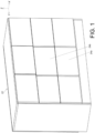
- a cabinet apparatus includes a cabinet 22 and a slide rail mechanism adapted for the cabinet 22.
- a plurality of drawers are arranged on the cabinet 22 along a vertical direction, i.e., a height direction of the cabinet 22, and/or a transverse direction, i.e., a lateral direction of the cabinet 22.
- a first drawer 24a and a second drawer 24b can be arranged on the cabinet 22 along the vertical direction.
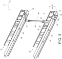
- the slide rail mechanism includes a first slide rail assembly 26 and a second slide rail assembly 28.
- the first slide rail assembly 26 and a second slide rail assembly 28 are configured to be arranged on a wall W of the cabinet 22 for supporting the first drawer 24a and the second drawer 24b respectively.
- the slide rail mechanism further includes a connecting member 30 movably mounted on one of the cabinet 22, the first slide rail assembly 26 and the second slide rail assembly 28.
- the connecting member 30 can be movably mounted on the first slide rail assembly 26.
- the present invention is not limited to this embodiment.
- the first slide rail assembly 26 and the second slide rail assembly 28 can have substantially identical structures.
- the first slide rail assembly 26 includes a first rail 32, e.g., a fixed rail, and a second rail 34, e.g., a movable rail, longitudinal displaceable with respect to the first rail 32
- the second slide rail assembly 28 includes a third rail 36, e.g., a fixed rail, and a fourth rail 38, e.g., a movable rail, longitudinal displaceable with respect to the third rail 36.
- the first slide rail assembly 26 further includes a first middle rail 40 movably mounted between the first rail 32 and the second rail 34
- the second slide rail assembly 28 further includes a second middle rail 42 movably mounted between the third rail 36 and the fourth rail 38.
- the first middle rail 40 and the second middle rail 42 do not corporate with the connecting member 30. Understandably, in another embodiment, the first middle rail and the second middle rail can be omitted. It should be noticed that, in this embodiment, by way of example, a longitudinal direction, i.e., a length direction or a displacing direction of a rail, can be parallel to an X axis.
- the transverse direction i.e., a lateral direction of the rail or the lateral direction of the cabinet 22, can be parallel to a Y axis.
- the vertical direction i.e., a height direction of the rail or the height direction of the cabinet 22, can be parallel to the Z axis.
- the connecting member 30 is movably mounted between the first slide rail assembly 26 and the second slide rail assembly 28.
- the first rail 32 of the first slide rail assembly 26 and the third rail 36 of the second slide rail assembly 28 can have substantially identical structures
- the second rail 34 of the first slide rail assembly 26 and the fourth rail 38 of the second slide rail assembly 28 can have substantially identical structures.
- the first rail 32 of the first slide rail assembly 26 can include a first vertical portion 44, a first supporting portion 46 and a first horizontal portion 48 connected between the first vertical portion 44 and the first supporting portion 46
- the first rail 32 of the first slide rail assembly 26 can be configured to be mounted on the wall W of the cabinet 22 by a plurality of mounting features 50 of the first vertical portion 44.
- the connecting member 30 is movably mounted on the first vertical portion 44 of the first rail 32, such that the connecting member 30 is movable along the height direction of the cabinet 22, e.g., the Z axis.
- the second rail 34 of the first slide rail assembly 26 and the fourth rail 38 of the second slide rail assembly 28 can be configured to support the first drawer 24a and the second drawer 24b respectively.
- the first vertical portion 44 and the first supporting portion 46 are substantially perpendicularly connected to the first horizontal portion 48.
- the first vertical portion 44 has a first height K1
- the first supporting portion 46 has a second height K2 less than the first height K1.
- the first vertical portion 44 and the first supporting portion 46 are located at two opposite sides of the first horizontal portion 48.
- each of the first slide rail assembly 26 and the second slide rail assembly 28 includes a plurality of slide-aiding devices.
- the first slide rail assembly 26 includes a first slide-aiding device and a second slide-aiding device.
- the first slide-aiding device is movably supported between the first rail 32 and the first middle rail 40 of the first slide rail assembly 26 for facilitating a smooth relative displacement of the first middle rail 40 and the first rail 32 of the first slide rail assembly 26.
- the second slide-aiding device is movably supported between the second rail 34 and the first middle rail 40 of the first slide rail assembly 26 for facilitating a smooth relative displacement of the second rail 34 and the first middle rail 40 of the first slide rail assembly 26.
- the connecting member 30 includes a first extending portion 52, a second extending portion 54 and a middle portion 56 connected between the first extending portion 52 and the second extending portion 54.
- a predetermined space S is arranged on the first vertical portion 44 of the first rail 32 of the first slide rail assembly 26 and configured to at least partially accommodate the first extending portion 52 of the connecting member 30.
- a plurality of retaining features 58 are further arranged on the first vertical portion 44 of the first rail 32 of the first slide rail assembly 26 and configured to retain or support the first extending portion 52 of the connecting member 30, so as to facilitate a stable movement of the connecting member 30 with respect to the first rail 32 of the first slide rail assembly 26.
- the connecting member 30 is a rod, and a longitudinal direction of the connecting member 30 is substantially parallel to the height direction of the cabinet 22.
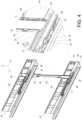
- a first self-closing device 60 and a second self-closing device 62 are arranged on the first slide rail assembly 26 and the second slide rail assembly 28, respectively.
- the first self-closing device 60 and the second self-closing device 62 can have substantially identical structures. Detailed description for the second self-closing device 62 is omitted for simplicity.
- the first self-closing device 60 is arranged on the first rail 32 of the first slide rail assembly 26 and includes a first auxiliary member 64
- the second self-closing device 62 is arranged on the third rail 36 of the second slide rail assembly 28 and includes a third auxiliary member 70.
- a first working feature 66 is arranged on the second rail 34 of the first slide rail assembly 26 and movable together with the second rail 34 of the first slide rail assembly 26 when the second rail 34 of the first slide rail assembly 26 displaces with respect to the first rail 32 of the first slide rail assembly 26, and a second working feature 68 is arranged on the fourth rail 38 of the second slide rail assembly 28 and movable together with the fourth rail 38 of the second slide rail assembly 28 when the fourth rail 38 of the second slide rail assembly 28 displaces with respect to the third rail 36 of the second slide rail assembly 28.
- each of the first working feature 66 and the second working feature 68 can be a protrusion, a pin or the like.
- the present invention is not limited to this embodiment.
- the second rail 34 of the first slide rail assembly 26 is located at a first retracted position R with respect to the first rail 32 of the first slide rail assembly 26, and the first auxiliary member 64 of the first self-closing device 60 releasably catches the first working feature 66 on the second rail 34 of the first slide rail assembly 26.
- the fourth rail 38 of the second slide rail assembly 28 is located at a second retracted position with respect to the third rail 36 of the second slide rail assembly 28, and the third auxiliary member 70 of the second self-closing device 62 releasably catches the second working feature 68 on the fourth rail 38 of the second slide rail assembly 28.
- the first self-closing device 60 further includes a second auxiliary member 72 located adjacent to the first auxiliary member 64, and the second self-closing device 62 further includes a fourth auxiliary member 74 located adjacent to the third auxiliary member 70.
- a first through hole 76 is arranged on the first rail 32 of the first slide rail assembly 26, e.g., the first horizontal portion 48 of the first rail 32 of the first slide rail assembly 26, and a second through hole 82 is arranged on the third rail 36 of the second slide rail assembly 28, e.g., a second horizontal portion 80 of the third rail 36 of the second slide rail assembly 28.
- the connecting member 30 is located at a first predetermined position H1.
- the connecting member 30, e.g., the second extending portion 54 of the connecting member 30 does not block the fourth auxiliary member 74 of the second self-closing device 62.
- the first self-closing device 60 further includes a first resilient member 84 configured to provide a resilient force to the first auxiliary member 64 and/or the second auxiliary member 72.
- the first resilient member 84 can be a compression spring or an extension spring.
- the present invention is not limited to this embodiment.
- the first auxiliary member 64 includes a first catch portion 86 configured to releasably catch the first working feature 66 on the second rail 34 of the first slide rail assembly 26.
- the first catch portion 86 can be a hook having an auxiliary space configured to receive a portion of the first working feature 66.
- the present invention is not limited to this embodiment.
- the first self-closing device 60 further includes a first base 88 configured to be connected, e.g., fixedly connected, to the first rail 32, e.g., the first horizontal portion 48 of the first rail 32, of the first slide rail assembly 26.
- a first base 88 configured to be connected, e.g., fixedly connected, to the first rail 32, e.g., the first horizontal portion 48 of the first rail 32, of the first slide rail assembly 26.
- the first resilient member 84 includes a first end portion 94a connected to the second auxiliary member 72 and a second end portion 94b connected to the first base 88.
- one of the first auxiliary member 64 and the second auxiliary member 72 includes a first guiding feature 96.
- the second auxiliary member 72 includes the first guiding feature 96.
- the connecting member 30, e.g., the first extending portion 52 of the connecting member 30, includes a second guiding feature 98 for cooperating with the first guiding feature 96 to allow the connecting member 30 to be moved in response to the second auxiliary member 72.
- at least one of the first guiding feature 96 and the second guiding feature 98 can be an inclined surface or an arc surface.
- the present invention is not limited to this embodiment.
- the first slide rail assembly 26 further includes a first damping device 100
- the second slide rail assembly 28 further includes a second damping device.
- the first damping device 100 and the second damping device can have substantially identical structures. Detailed description for the second damping device is omitted for simplicity.
- the first damping device 100 includes a first object 102 and a second object 104 movable with respect to each other.
- One of the first object 102 and the second object 104 is a cylinder equipped with a buffering medium and/or an auxiliary spring therein, and the other one of the first object 102 and the second object 104 is a piston rod.
- the first damping device 100 is located at a position corresponding to the first auxiliary member 64.
- the second rail 34 of the first slide rail assembly 26 When the second rail 34 of the first slide rail assembly 26 is displaced with respect to the first rail 32 of the firs slide rail assembly 26 to the first retracted position R, one of the first object 102 and the second object 104 can abut against the first auxiliary member 64 to reduce a displacing speed of the second rail 34 of the first slide rail assembly 26.
- the second object 104 can be configured to abut against the first auxiliary member 64.
- the first auxiliary member 64 and the second auxiliary member 72 are connected to each other.
- the first auxiliary member 64 and the second auxiliary member 72 can be pivotally connected to each other via a shaft 106.
- the present invention is not limited to this embodiment.
- the third auxiliary member 70 and the fourth auxiliary member 74 can be pivotally connected to each other.
- the present invention is not limited to this embodiment.
- the first auxiliary member 64 includes a first supporting section 108
- the second auxiliary member 72 includes a second supporting section 110.
- the first supporting section 108 and the second supporting section 110 are configured to cooperate with the first base 88.
- each of the first supporting section 108 and the second supporting section 110 can be a protruding portion.
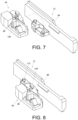
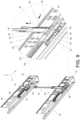
- FIG. 9 illustrates the first working feature 66, which is arranged on the second rail 34 of the first slide rail assembly 26, and the second working feature 68, which is arranged on the fourth rail 38 of the second slide rail assembly 28, without the first middle rail 40 and the second rail 34 of the first slide rail assembly 26 and the second middle rail 42 and the fourth rail 38 of the second slide rail assembly 28.
- the connecting member 30 is moved for preventing the fourth rail 38 of the second slide rail assembly 28 from displacing with respect to the third rail 36 of the second slide rail assembly 28 along the opening direction D1.
- the connecting member 30 can be driven from the first predetermined position H1 as shown in FIG. 5 to a second predetermined position H2 as shown in FIG.
- the connecting member 30, e.g., the second extending portion 54 of the connecting member 30, passes through the second through hole 82 on the third rail 36 of the second slide rail assembly 28, e.g., the second horizontal portion 80 of the third rail 36 of the second slide rail assembly 28, so as to block the fourth auxiliary member 74 for preventing the fourth rail 38 of the second slide rail assembly 28 from displacing with respect to the third rail 36 of the second slide rail assembly 28 along the opening direction D1, i.e., retaining the fourth rail 38 of the second slide rail assembly 28 at a second retracted position as shown in FIG. 5 . Accordingly, the second drawer 24b cannot be opened with respect to the cabinet 22 respectively because the fourth rail 38 of the second slide rail assembly 28 is restrained from displacing with respect to the third rail 36 of the second slide rail assembly 28 along the opening direction D1 .
- the first supporting section 108 of the first auxiliary member 64 and the second supporting section 110 of the second auxiliary member 72 are located in a longitudinal path 90 of the first base 88.
- the first base 88 further includes a bending path 92 bent with respect to the longitudinal path 90.
- the first auxiliary member 64 moves along the longitudinal path 90 and the bending path 92.
- the first auxiliary member 64 can include a corresponding supporting section 112 configured to engage with a wall of the bending path 94 to retain the first auxiliary member 64 at the pivoting position for maintaining a resilient deformation of the resilient member 84.
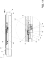
- the second rail 34 of the first slide rail assembly 26 is located at the first extended position E, the second object 104 is fully extended with respect to the first object 102, i.e., the first damping device 100 is in a pre-buffering state.
- the first auxiliary member 64 abuts against the second object 104 of the first damping device 100 for driving the second object 104 of the first damping device 100 to move with respect to the first object 102 of the first damping device 100, such that the displacing speed of the second rail 34 is reduced.
- the fourth auxiliary member 74 moves to a blocking position along the opening direction D1 for blocking the connecting member 30, such that the connecting member 30 cannot move along the height direction M, i.e., the connecting member 30 can be retained at the first predetermined height H1.
- the connecting member 30 retained at the first predetermined height H1 can block the second auxiliary member 72 for preventing the second rail 34 of the first slide rail assembly 26 from displacing with respect to the first rail 32 of the first slide rail assembly 26 along the opening direction D1.
- the slide rail mechanism includes the following characteristics.
Landscapes
- Engineering & Computer Science (AREA)
- Mechanical Engineering (AREA)
- Drawers Of Furniture (AREA)
- General Engineering & Computer Science (AREA)
- Seats For Vehicles (AREA)
Applications Claiming Priority (1)
| Application Number | Priority Date | Filing Date | Title |
|---|---|---|---|
| TW112105467A TWI842394B (zh) | 2023-02-14 | 2023-02-14 | 滑軌機構 |
Publications (1)
| Publication Number | Publication Date |
|---|---|
| EP4417088A1 true EP4417088A1 (de) | 2024-08-21 |
Family
ID=87517287
Family Applications (1)
| Application Number | Title | Priority Date | Filing Date |
|---|---|---|---|
| EP23188149.1A Pending EP4417088A1 (de) | 2023-02-14 | 2023-07-27 | Gleitschienenmechanismus |
Country Status (4)
| Country | Link |
|---|---|
| US (1) | US12364331B2 (de) |
| EP (1) | EP4417088A1 (de) |
| JP (1) | JP7800927B2 (de) |
| TW (1) | TWI842394B (de) |
Families Citing this family (2)
| Publication number | Priority date | Publication date | Assignee | Title |
|---|---|---|---|---|
| TWI870191B (zh) * | 2024-01-03 | 2025-01-11 | 川湖科技股份有限公司 | 滑軌機構 |
| TWI863863B (zh) * | 2024-05-06 | 2024-11-21 | 川湖科技股份有限公司 | 滑軌機構及其調整裝置 |
Citations (2)
| Publication number | Priority date | Publication date | Assignee | Title |
|---|---|---|---|---|
| EP1441092B1 (de) | 2003-01-27 | 2005-11-16 | Anton Schneider Gmbh & Co. | Schliessvorrichtung für Schubladenschränke |
| EP1500763B1 (de) * | 2003-07-24 | 2008-02-27 | Fulterer Gesellschaft m.b.H. | Ausziehsperreinrichtung für mindestens zwei wechselweise aus einem Möbelkorpus ausziehbare Schubladen |
Family Cites Families (11)
| Publication number | Priority date | Publication date | Assignee | Title |
|---|---|---|---|---|
| US3767280A (en) * | 1972-03-14 | 1973-10-23 | Eddy Match Co Ltd | Locking system for filing cabinets |
| US4609233A (en) * | 1983-11-03 | 1986-09-02 | Timberline Supply, Ltd. | Furniture locking system |
| US5352030A (en) * | 1992-09-11 | 1994-10-04 | Wolfgang Derle | Anti-tip device |
| US5634701A (en) * | 1994-08-31 | 1997-06-03 | Fireking International, Inc. | Multi-drawer cabinet having a drawer lock-out mechanism |
| US6186606B1 (en) * | 1998-10-17 | 2001-02-13 | The Marvel Group, Inc. | Lateral File Locking System |
| GB2380516B (en) * | 2001-10-05 | 2005-07-27 | Accuride Int Ltd | Rear interlock |
| US7469979B2 (en) * | 2004-03-19 | 2008-12-30 | Steelcase Inc. | Pedestal system |
| US7533946B2 (en) * | 2005-08-25 | 2009-05-19 | Knape & Vogt Manufacturing Company | Closing device for drawers |
| MY155806A (en) * | 2010-07-29 | 2015-11-30 | Harn Marketing Sdn Bhd | Drawer guide rail system |
| TWI599332B (zh) | 2016-08-31 | 2017-09-21 | 川湖科技股份有限公司 | 用於可活動傢俱件的回歸機構 |
| CN115104867A (zh) * | 2022-04-01 | 2022-09-27 | 清远市星徽精密制造有限公司 | 一种具有自锁互锁功能的抽屉导轨 |
-
2023
- 2023-02-14 TW TW112105467A patent/TWI842394B/zh active
- 2023-07-11 US US18/220,287 patent/US12364331B2/en active Active
- 2023-07-27 EP EP23188149.1A patent/EP4417088A1/de active Pending
- 2023-10-11 JP JP2023175629A patent/JP7800927B2/ja active Active
Patent Citations (2)
| Publication number | Priority date | Publication date | Assignee | Title |
|---|---|---|---|---|
| EP1441092B1 (de) | 2003-01-27 | 2005-11-16 | Anton Schneider Gmbh & Co. | Schliessvorrichtung für Schubladenschränke |
| EP1500763B1 (de) * | 2003-07-24 | 2008-02-27 | Fulterer Gesellschaft m.b.H. | Ausziehsperreinrichtung für mindestens zwei wechselweise aus einem Möbelkorpus ausziehbare Schubladen |
Also Published As
| Publication number | Publication date |
|---|---|
| US20240268555A1 (en) | 2024-08-15 |
| JP2024115507A (ja) | 2024-08-26 |
| US12364331B2 (en) | 2025-07-22 |
| TWI842394B (zh) | 2024-05-11 |
| JP7800927B2 (ja) | 2026-01-16 |
| TW202432029A (zh) | 2024-08-16 |
Similar Documents
| Publication | Publication Date | Title |
|---|---|---|
| EP4417088A1 (de) | Gleitschienenmechanismus | |
| EP3609304B1 (de) | Gleitschienenmechanismus und haltevorrichtung dafür | |
| US12203292B2 (en) | Slide rail mechanism | |
| EP4477823A1 (de) | Verriegelungskit und zugehörige möbelanordnung | |
| EP4321053A1 (de) | Schienenanordnung | |
| US12390009B2 (en) | Slide rail mechanism | |
| EP4393349A1 (de) | Gleitschienenanordnung | |
| US20250043819A1 (en) | Slide rail assembly | |
| EP4461160A1 (de) | Möbelanordnung | |
| CN117461952A (zh) | 一种导轨用回位缓冲装置及具有其的抽屉导轨 | |
| US12390008B2 (en) | Slide rail mechanism | |
| JP7471494B1 (ja) | スライドレール機構 | |
| US12419417B2 (en) | Slide rail assembly | |
| EP4521864A1 (de) | Antriebsmechanismus | |
| EP4360509B1 (de) | Ausziehbares regal | |
| EP4523567A1 (de) | Gleitschienenanordnung | |
| EP4736711A1 (de) | Gleitschienenanordnung | |
| CN210643259U (zh) | 滑轨阻尼自锁结构 | |
| JP3300590B2 (ja) | 昇降式収納棚 | |
| EP4581983B1 (de) | Gleitschienenmechanismus | |
| EP4480344A1 (de) | Gleitschienenanordnung | |
| CN110753471B (zh) | 滑轨机构及其托架装置 |
Legal Events
| Date | Code | Title | Description |
|---|---|---|---|
| PUAI | Public reference made under article 153(3) epc to a published international application that has entered the european phase |
Free format text: ORIGINAL CODE: 0009012 |
|
| STAA | Information on the status of an ep patent application or granted ep patent |
Free format text: STATUS: THE APPLICATION HAS BEEN PUBLISHED |
|
| AK | Designated contracting states |
Kind code of ref document: A1 Designated state(s): AL AT BE BG CH CY CZ DE DK EE ES FI FR GB GR HR HU IE IS IT LI LT LU LV MC ME MK MT NL NO PL PT RO RS SE SI SK SM TR |
|
| STAA | Information on the status of an ep patent application or granted ep patent |
Free format text: STATUS: REQUEST FOR EXAMINATION WAS MADE |
|
| 17P | Request for examination filed |
Effective date: 20241105 |
|
| RBV | Designated contracting states (corrected) |
Designated state(s): AL AT BE BG CH CY CZ DE DK EE ES FI FR GB GR HR HU IE IS IT LI LT LU LV MC ME MK MT NL NO PL PT RO RS SE SI SK SM TR |