EP4521864A1 - Antriebsmechanismus - Google Patents
Antriebsmechanismus Download PDFInfo
- Publication number
- EP4521864A1 EP4521864A1 EP24166203.0A EP24166203A EP4521864A1 EP 4521864 A1 EP4521864 A1 EP 4521864A1 EP 24166203 A EP24166203 A EP 24166203A EP 4521864 A1 EP4521864 A1 EP 4521864A1
- Authority
- EP
- European Patent Office
- Prior art keywords
- casing
- operating member
- state
- wall
- driving mechanism
- Prior art date
- Legal status (The legal status is an assumption and is not a legal conclusion. Google has not performed a legal analysis and makes no representation as to the accuracy of the status listed.)
- Pending
Links
Images





Classifications
-
- H—ELECTRICITY
- H05—ELECTRIC TECHNIQUES NOT OTHERWISE PROVIDED FOR
- H05K—PRINTED CIRCUITS; CASINGS OR CONSTRUCTIONAL DETAILS OF ELECTRIC APPARATUS; MANUFACTURE OF ASSEMBLAGES OF ELECTRICAL COMPONENTS
- H05K7/00—Constructional details common to different types of electric apparatus
- H05K7/14—Mounting supporting structure in casing or on frame or rack
- H05K7/1485—Servers; Data center rooms, e.g. 19-inch computer racks
- H05K7/1488—Cabinets therefor, e.g. chassis or racks or mechanical interfaces between blades and support structures
- H05K7/1489—Cabinets therefor, e.g. chassis or racks or mechanical interfaces between blades and support structures characterized by the mounting of blades therein, e.g. brackets, rails, trays
-
- H—ELECTRICITY
- H05—ELECTRIC TECHNIQUES NOT OTHERWISE PROVIDED FOR
- H05K—PRINTED CIRCUITS; CASINGS OR CONSTRUCTIONAL DETAILS OF ELECTRIC APPARATUS; MANUFACTURE OF ASSEMBLAGES OF ELECTRICAL COMPONENTS
- H05K5/00—Casings, cabinets or drawers for electric apparatus
- H05K5/02—Details
- H05K5/0217—Mechanical details of casings
- H05K5/023—Handles; Grips
-
- A—HUMAN NECESSITIES
- A47—FURNITURE; DOMESTIC ARTICLES OR APPLIANCES; COFFEE MILLS; SPICE MILLS; SUCTION CLEANERS IN GENERAL
- A47B—TABLES; DESKS; OFFICE FURNITURE; CABINETS; DRAWERS; GENERAL DETAILS OF FURNITURE
- A47B88/00—Drawers for tables, cabinets or like furniture; Guides for drawers
- A47B88/90—Constructional details of drawers
-
- H—ELECTRICITY
- H05—ELECTRIC TECHNIQUES NOT OTHERWISE PROVIDED FOR
- H05K—PRINTED CIRCUITS; CASINGS OR CONSTRUCTIONAL DETAILS OF ELECTRIC APPARATUS; MANUFACTURE OF ASSEMBLAGES OF ELECTRICAL COMPONENTS
- H05K7/00—Constructional details common to different types of electric apparatus
- H05K7/14—Mounting supporting structure in casing or on frame or rack
- H05K7/1401—Mounting supporting structure in casing or on frame or rack comprising clamping or extracting means
-
- A—HUMAN NECESSITIES
- A47—FURNITURE; DOMESTIC ARTICLES OR APPLIANCES; COFFEE MILLS; SPICE MILLS; SUCTION CLEANERS IN GENERAL
- A47B—TABLES; DESKS; OFFICE FURNITURE; CABINETS; DRAWERS; GENERAL DETAILS OF FURNITURE
- A47B88/00—Drawers for tables, cabinets or like furniture; Guides for drawers
- A47B88/90—Constructional details of drawers
- A47B2088/901—Drawers having a lifting mechanism
Definitions
- the present invention relates a driving mechanism according to the pre-characterizing clause of claim 1.
- U.S. Patent Publication No. 2023/0049413 A1 it discloses a tray module adapted for a chassis.
- the chassis includes at least two side plates.
- Each side plate has a track member.
- the track member includes a first horizontal section, an inclined section and a second horizontal section.
- the inclined section is connected to and located between the first horizontal section and the second horizontal section.
- the first horizontal section, the inclined section and the second horizontal section cooperatively form an S-shaped structure substantially.
- the tray module includes a carrier body, at least two first connecting rods, and at least two second connecting rods.
- Each first connecting rod has a movable end and a driven end. The movable end of each first connecting rod is pivotally connected to the carrier body and slidably disposed in the corresponding track member.
- Each second connecting rod has a pivotal end, an operating end and a pivotal connection portion located between the pivotal end and the operating end.
- the pivotal end of each second connecting rod is pivotally connected to the corresponding side plate.
- the driven end of each first connecting rod is pivotally connected to the pivotal connection portion of the corresponding second connecting rod.
- the present invention aims at providing a driving mechanism for driving a relative movement of two casings by utilizing an operating member.
- the claimed driving mechanism includes a first casing, a second casing and at least one operating member.
- the second casing is arranged on the first casing.
- the at least one operating member includes a first operating member movably mounted on one of the first casing and the second casing.
- the at least one operating member drives another one of the first casing and the second casing to linearly move from a first predetermined position to a second predetermined position along a first vertical direction.
- the another one of the first casing and the second casing linearly moves from the second predetermined position to the first predetermined position along a second vertical direction opposite to the first vertical direction.
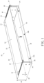
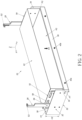
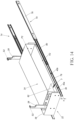
- a driving mechanism 20 includes a first casing 22, a second casing 24 and at least one operating member.
- the at least one operating member includes a first operating member 26 and a second operating member 28, which are substantially symmetrical to each other.
- a longitudinal direction can be defined by a length direction of the first casing 22 or the second casing 24, and parallel to an X axis.
- a transverse direction can be defined by a lateral direction or a width direction of the first casing 22 or the second casing 24, and parallel to a Y axis.
- a vertical direction can be defined by a height direction of the first casing 22 or the second casing 24, and parallel to a Z axis.
- the second casing 24 is arranged on the first casing 22. As shown in FIG. 1 , in this embodiment, by way of example, the second casing 24 is disposed above a supporting portion 30 of the first casing 22.
- the first operating member 26 and the second operating member 28 are movably mounted on one of the first casing 22 and the second casing 24, and the other one of the first casing 22 and the second casing 24 moves in response to movements of the first operating member 26 and the second operating member 28.
- the first operating member 26 and the second operating member 28 are movably mounted on the first casing 22.
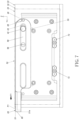
- the first operating member 26 and the second operating member 28 drive the second casing 24 to move relative to the first casing 22 from a first predetermined position P1 as shown in FIG. 1 to a second predetermined position P2 as shown in FIG.
- first vertical direction D1 e.g., an upward direction
- second vertical direction D2 e.g., a downward direction
- the first casing 22 includes a first wall 32 and a second wall 34.
- a first space K1 of the first casing 22 is defined between the first wall 32 and the second wall 34 and configured to receive the second casing 24.
- the first wall 32 and the second wall 34 of the first casing 22 are a front wall and a rear wall of the first casing 22, respectively.
- the first casing 22 further includes a first lateral wall 36 and a second lateral wall 38.
- the first lateral wall 36 and the second lateral wall 38 are a left lateral wall and a right lateral wall of the first casing 22, respectively, and a first height H1 of the first lateral wall 36 is less than a second height H2 of the second lateral wall 38.
- the present invention is not limited to this embodiment.
- the aforementioned configuration of the first casing 22 can expose the second casing 24 so as to provide lateral access to the second casing 24 received in the first casing 22, such that a user can detach or unload at least one carried object from a second space K2 of the second casing 24 or place the at least one carried object into the second space K2 of the second casing 24 easily.
- the supporting portion 30 of the first casing 22 can be a bottom portion of the first casing 22, e.g., a bottom surface of the first casing 22.
- a plurality of mounting features are arranged on each of the first lateral wall 36 and the second lateral wall 38 of the first casing 22 for easy mounting of the driving mechanism 20.
- the plurality of mounting features can at least include a first mounting feature 40a and a second mounting feature 40b.
- the structural configuration of the first operating member 26, the first casing 22 and the second casing 24 can be substantially symmetrical to the structural configuration of the second operating member 28, the first casing 22 and the second casing 24.
- the operational principle of the first operating member 26 is substantially identical to the operational principle of the second operating member 28.
- Detailed description for the structural configuration of the first operating member 26 and the first wall 32 of the first casing 22 and the operational principle of the first operating member 26 is provided as follows, and detailed description for the structural configuration of the second operating member 28 and the second wall 34 of the first casing 22 and the operational principle of the second operating member 28 is omitted herein for simplicity.
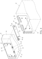
- a shaft member 42 is arranged on one of the first wall 32 of the first casing 22 and the first operating member 26, and an elongated hole 44 is arranged on the other one of the first wall 32 of the first casing 22 and the first operating member 26 for allowing the shaft member 42 to pass therethrough.
- the elongated hole 44 is arranged on the first operating member 26, and the shaft member 42 is connected to, e.g., fixedly connected to, the first wall 32 of the first casing 22, and passes through a portion of the elongated hole 44 arranged on the first operating member 26.
- the first operating member 26 includes an engaging feature 46, and a first corresponding feature 48 and a second corresponding feature 50 are arranged on the first wall 32 of the first casing 22.
- the engaging feature 46 is configured to engage with the first corresponding feature 48 or the second corresponding feature 50 selectively.
- the engaging feature 46 can be a notch or a C-shaped slot formed on a wall of the first operating member 26, and the first corresponding feature 48 and the second corresponding feature 50 can be two protrusions.
- the present invention is not limited to this embodiment.
- the second casing 24 includes a first predetermined wall 52 and a second predetermined wall 54.
- the first predetermined wall 52 and the second predetermined wall 54 of the second casing 24 can be a front wall and a rear wall of the second casing 24, respectively.
- a driving member 56 is arranged on one of the first operating member 26 and the second casing 24, e.g., the first predetermined wall 52 of the second casing 24, and a predetermined hole 58 is arranged on the other one of the first operating member 26 and the second casing 24, e.g., the first predetermined wall 52 of the second casing 24, for allowing the driving member 56 to pass therethrough.
- the predetermined hole 58 has a predetermined length.
- a length direction of the predetermined hole 58 is substantially parallel to a length direction of the elongated hole 44.
- the driving member 56 can be a protrusion or a pin passing through a portion of the predetermined hole 58.
- the predetermined hole 58 is arranged on the second casing 24, e.g., the first predetermined wall 52 of the second casing 24, and the driving member 56 is arranged on the first operating member 26 and passes through a portion of the predetermined hole 58.
- the present invention is not limited to this embodiment.
- the first operating member 26 further includes an operating portion 60.
- the operating portion 60 and the engaging feature 46 are located adjacent to two opposite ends of the first operating member 26, respectively.
- the operating portion 60 and the engaging feature 46 are located adjacent to a first end E1 and a second end E2 of the first operating member 26, respectively.
- the first operating member 26 further includes an extending portion 62 connected between the first end E1 and the second end E2 of the first operating member 26, and the elongated hole 44 and the driving member 56 are arranged on the extending portion 62.
- the driving mechanism 20 further includes a resilient member 64 configured to provide a resilient force F to the first operating member 26.
- the resilient member 64 includes a first resilient portion 66 and at least one second resilient portion 68.
- the first resilient portion 66 is hooked on a predetermined feature 70 of the first operating member 26.
- the second resilient portion 68 is connected to the first casing 22.
- the second resilient portion 68 is connected to the shaft member 42 on the first wall 32 of the first casing 22.
- the present invention is not limited to this embodiment.
- At least one buffering device 72 is arranged on one of the first casing 22 and the second casing 24.
- the at least one buffering device 72 is arranged on the first wall 32 of the first casing 22 and can be a resilient object or a flexible object.
- the buffering device 72 can be a hydraulic support rod assembly or a recoil spring support rod assembly.
- the driving member 56 on the first operating member 26 is configured to pass through a portion of the predetermined hole 58 on the second casing 24.
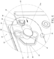
- the engaging feature 46 and the first corresponding feature 48 engage with each other for preventing the first operating ember 26 from moving away from the first state S1.
- the first operating member 26 in the first state S1 is retained at the first position S1a in response to the resilient force F provided by the resilient member 64 and acting on the second end E2 of the first operating member 26 for keeping engaging the engaging feature 46 with the first corresponding feature 48, such that the second casing 24 is locked at the first predetermined position P1 relative to the first casing 22.
- the first operating member 26 and the first wall 32 of the first casing 22 are substantially parallel to each other in the transverse direction, i.e., the lateral direction, or extend along the Y axis in parallel.
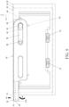
- the engaging feature 46 and the first corresponding feature 48 disengage from each other for allowing the first operating member 26 to move from the first state S1 to the second state S2 along a first predetermined direction R1.
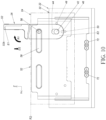
- the first operating member 26 drives the second casing 24 to linearly move relative to the first casing 22 from the first predetermined position P1 as shown in FIG. 8 to the second predetermined position P2 as shown in FIG. 10 through an intermediate position as shown in FIG. 9 along the first vertical direction D1.
- the second casing 24 moves from the second predetermined position P2 to a third predetermined position P3, which is slightly lower than the second predetermined position P2, to be locked at the third predetermined position P3 relative to the first casing 22 to allow the user to detach or unload the at least one carried object from the second space K2 of the second casing 24 or place the at least one carried object into the second space K2 of the second casing 24 easily.
- the first operating member 26 can be moved from the second state S2 to the first state S 1 along a second predetermined direction R2 opposite to the first predetermined direction R1 by operating the operating portion 60 of the operating member 26 with a fourth force F4.
- the first operating member 26 drives the second casing 24 to linearly move relative to the first casing 22 from the second predetermined position P2 to the first predetermined position P1 along the second vertical direction D2.
- the first operating member 26 in the first state S1 can be moved from the second position S1b to the first position S1a in response to the resilient force F provided by the resilient member 64, so as to engage the engaging feature 46 with the first corresponding feature 48 for preventing the first operating member 26 from moving away from the first state S1 to lock the second casing 24 at the first predetermined position P1 relative to the first casing 22.
- the at least one buffering device 72 on the first casing 22 is configured to be in contact with the second casing 24, so as to provide a shock absorbing effect or a noise reducing effect.
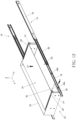
- the driving mechanism 20 is adapted for at least one slide rail assembly 74.
- the at least one slide rail assembly 74 includes two slide rail assemblies 74 substantially symmetrical to each other.
- each of the two slide rail assemblies 74 includes a first rail 76 and a second rail 78 displaceable relative to the first rail 76.
- each of the two slide rail assemblies 74 further includes a third rail 80 movably mounted between the first rail 76 and the second rail 78.
- the first rail 76 is fixedly mounted on a targeted object, e.g., a cabinet or a rack.
- Each of the first lateral wall 36 and the second lateral wall 38 of the first casing 22 is mounted on the corresponding second rail 78 by the corresponding first mounting feature 40a and the corresponding second mounting feature 40b.
- the at least one carried object 82 is still above the corresponding second rail 78 having the predetermined height h for allowing the user to detach or unload the at least one carried object 82 from the second space K2 of the second casing 24 along the lateral direction T.
- the driving mechanism can include the first operating member only, and the second operating member can be omitted.
- the present invention has following characteristics:
Landscapes
- Engineering & Computer Science (AREA)
- Microelectronics & Electronic Packaging (AREA)
- Computer Hardware Design (AREA)
- General Engineering & Computer Science (AREA)
- Drawers Of Furniture (AREA)
- Casings For Electric Apparatus (AREA)
- Accommodation For Nursing Or Treatment Tables (AREA)
- Switches With Compound Operations (AREA)
- Transmission Devices (AREA)
- Manipulator (AREA)
- Mechanical Engineering (AREA)
Applications Claiming Priority (1)
| Application Number | Priority Date | Filing Date | Title |
|---|---|---|---|
| TW112134170A TWI850103B (zh) | 2023-09-06 | 2023-09-06 | 驅動機構 |
Publications (1)
| Publication Number | Publication Date |
|---|---|
| EP4521864A1 true EP4521864A1 (de) | 2025-03-12 |
Family
ID=90482333
Family Applications (1)
| Application Number | Title | Priority Date | Filing Date |
|---|---|---|---|
| EP24166203.0A Pending EP4521864A1 (de) | 2023-09-06 | 2024-03-26 | Antriebsmechanismus |
Country Status (4)
| Country | Link |
|---|---|
| US (1) | US12598715B2 (de) |
| EP (1) | EP4521864A1 (de) |
| JP (1) | JP7725785B2 (de) |
| TW (1) | TWI850103B (de) |
Families Citing this family (1)
| Publication number | Priority date | Publication date | Assignee | Title |
|---|---|---|---|---|
| US20260040466A1 (en) * | 2024-07-30 | 2026-02-05 | Hanwit Precision Industries Ltd. | Dual-axis handle |
Citations (2)
| Publication number | Priority date | Publication date | Assignee | Title |
|---|---|---|---|---|
| CN109587994A (zh) * | 2017-09-28 | 2019-04-05 | 南宁富桂精密工业有限公司 | 手柄组件及应用该手柄组件的设备 |
| TWI783647B (zh) * | 2021-08-16 | 2022-11-11 | 緯創資通股份有限公司 | 托盤模組及具該托盤之伺服器 |
Family Cites Families (14)
| Publication number | Priority date | Publication date | Assignee | Title |
|---|---|---|---|---|
| US7771218B2 (en) * | 2008-05-05 | 2010-08-10 | Dell Products L.P. | Electrical coupler mating system |
| CN102791103B (zh) * | 2012-07-20 | 2015-07-29 | 华为技术有限公司 | 一种插拔机构、包含该插拔机构的插框和成品板 |
| TWI507851B (zh) * | 2013-09-23 | 2015-11-11 | Wistron Corp | 可卸式托架及電子裝置 |
| TWI625090B (zh) * | 2016-05-30 | 2018-05-21 | 仁寶電腦工業股份有限公司 | 機箱結構 |
| CN106249817B (zh) * | 2016-07-29 | 2019-11-19 | 华为技术有限公司 | It设备支架、机箱及服务器 |
| CN107787137B (zh) * | 2016-08-30 | 2020-04-10 | 纬创资通(中山)有限公司 | 电子装置及托盘 |
| CN106647966B (zh) * | 2016-12-02 | 2019-09-17 | 英业达科技有限公司 | 服务器 |
| CN110632984B (zh) * | 2018-06-21 | 2021-04-30 | 纬联电子科技(中山)有限公司 | 托盘机构及其服务器设备 |
| CN109407770B (zh) * | 2018-09-21 | 2021-09-28 | 英业达科技有限公司 | 服务器 |
| CN113687695B (zh) * | 2020-05-19 | 2023-12-08 | 富联精密电子(天津)有限公司 | 框架结构和伺服器 |
| CN115437467A (zh) * | 2021-06-01 | 2022-12-06 | 纬联电子科技(中山)有限公司 | 托盘组件与包括托盘组件的电子装置 |
| CN116954316A (zh) * | 2022-04-14 | 2023-10-27 | 纬联电子科技(中山)有限公司 | 托盘组件与包含其的电子装置 |
| US11917786B2 (en) * | 2022-07-20 | 2024-02-27 | Dell Products, L.P. | Multi-purpose storage module for information technology equipment |
| US12557236B2 (en) * | 2024-04-26 | 2026-02-17 | Dell Products L.P. | Level holding components on a handle of a storage tray |
-
2023
- 2023-09-06 TW TW112134170A patent/TWI850103B/zh active
-
2024
- 2024-03-06 US US18/596,668 patent/US12598715B2/en active Active
- 2024-03-26 EP EP24166203.0A patent/EP4521864A1/de active Pending
- 2024-05-17 JP JP2024081132A patent/JP7725785B2/ja active Active
Patent Citations (3)
| Publication number | Priority date | Publication date | Assignee | Title |
|---|---|---|---|---|
| CN109587994A (zh) * | 2017-09-28 | 2019-04-05 | 南宁富桂精密工业有限公司 | 手柄组件及应用该手柄组件的设备 |
| TWI783647B (zh) * | 2021-08-16 | 2022-11-11 | 緯創資通股份有限公司 | 托盤模組及具該托盤之伺服器 |
| US20230049413A1 (en) | 2021-08-16 | 2023-02-16 | Wistron Corporation | Tray for expansion device and server having same |
Also Published As
| Publication number | Publication date |
|---|---|
| TW202512844A (zh) | 2025-03-16 |
| TWI850103B (zh) | 2024-07-21 |
| US20250072605A1 (en) | 2025-03-06 |
| JP2025037786A (ja) | 2025-03-18 |
| JP7725785B2 (ja) | 2025-08-20 |
| US12598715B2 (en) | 2026-04-07 |
Similar Documents
| Publication | Publication Date | Title |
|---|---|---|
| EP4521864A1 (de) | Antriebsmechanismus | |
| EP3322269B1 (de) | Klammervorrichtung und gleitschienenanordnung damit | |
| US6603655B2 (en) | Rotating and translating four bar media door for a computer chassis | |
| US5398164A (en) | Printed circuit card latching and stiffening assembly | |
| US6166900A (en) | Media drive canister vibration dampner and method of dampening | |
| US20010040203A1 (en) | Computer server mounting apparatus | |
| US8717753B2 (en) | Self-latching storage device module | |
| CN115705081A (zh) | 托盘模块及具有该托盘模块的服务器 | |
| JP2021154104A (ja) | スライドレールアセンブリ | |
| EP4501174A1 (de) | Gleitschienenanordnung | |
| EP4477823A1 (de) | Verriegelungskit und zugehörige möbelanordnung | |
| EP4417088A1 (de) | Gleitschienenmechanismus | |
| US7123485B1 (en) | Techniques for moving a power supply within an electronic cabinet | |
| EP4327697A1 (de) | Gleitschienenanordnung und gleitschienenkit | |
| EP4461160B1 (de) | Möbelanordnung | |
| US12419417B2 (en) | Slide rail assembly | |
| CN100482052C (zh) | 电子单元装载机构和磁盘阵列装置 | |
| EP4648558A1 (de) | Gestellmontagekit | |
| US10292284B1 (en) | Anti-falling mechanism for preventing an electronic component installed inside a casing from falling rapidly and electronic device therewith | |
| US12408289B2 (en) | Operation and maintenance device and cabinet having the same | |
| CN116163606A (zh) | 一种限位器、车门及车辆 | |
| EP4736711A1 (de) | Gleitschienenanordnung | |
| CN119603897A (zh) | 驱动机构 | |
| JP4713527B2 (ja) | 支持装置 | |
| EP4523567A1 (de) | Gleitschienenanordnung |
Legal Events
| Date | Code | Title | Description |
|---|---|---|---|
| PUAI | Public reference made under article 153(3) epc to a published international application that has entered the european phase |
Free format text: ORIGINAL CODE: 0009012 |
|
| STAA | Information on the status of an ep patent application or granted ep patent |
Free format text: STATUS: REQUEST FOR EXAMINATION WAS MADE |
|
| 17P | Request for examination filed |
Effective date: 20250117 |
|
| AK | Designated contracting states |
Kind code of ref document: A1 Designated state(s): AL AT BE BG CH CY CZ DE DK EE ES FI FR GB GR HR HU IE IS IT LI LT LU LV MC ME MK MT NL NO PL PT RO RS SE SI SK SM TR |