EP4417112A2 - Cathéter de cartographie d'électrode à haute densité - Google Patents
Cathéter de cartographie d'électrode à haute densité Download PDFInfo
- Publication number
- EP4417112A2 EP4417112A2 EP24186941.1A EP24186941A EP4417112A2 EP 4417112 A2 EP4417112 A2 EP 4417112A2 EP 24186941 A EP24186941 A EP 24186941A EP 4417112 A2 EP4417112 A2 EP 4417112A2
- Authority
- EP
- European Patent Office
- Prior art keywords
- understructure
- inboard
- outboard
- arm
- proximal
- Prior art date
- Legal status (The legal status is an assumption and is not a legal conclusion. Google has not performed a legal analysis and makes no representation as to the accuracy of the status listed.)
- Pending
Links
Images


Classifications
-
- A—HUMAN NECESSITIES
- A61—MEDICAL OR VETERINARY SCIENCE; HYGIENE
- A61B—DIAGNOSIS; SURGERY; IDENTIFICATION
- A61B18/00—Surgical instruments, devices or methods for transferring non-mechanical forms of energy to or from the body
- A61B18/04—Surgical instruments, devices or methods for transferring non-mechanical forms of energy to or from the body by heating
- A61B18/12—Surgical instruments, devices or methods for transferring non-mechanical forms of energy to or from the body by heating by passing a current through the tissue to be heated, e.g. high-frequency current
- A61B18/14—Probes or electrodes therefor
- A61B18/1492—Probes or electrodes therefor having a flexible, catheter-like structure, e.g. for heart ablation
-
- A—HUMAN NECESSITIES
- A61—MEDICAL OR VETERINARY SCIENCE; HYGIENE
- A61B—DIAGNOSIS; SURGERY; IDENTIFICATION
- A61B5/00—Measuring for diagnostic purposes; Identification of persons
- A61B5/24—Detecting, measuring or recording bioelectric or biomagnetic signals of the body or parts thereof
- A61B5/25—Bioelectric electrodes therefor
- A61B5/279—Bioelectric electrodes therefor specially adapted for particular uses
- A61B5/28—Bioelectric electrodes therefor specially adapted for particular uses for electrocardiography [ECG]
- A61B5/283—Invasive
- A61B5/287—Holders for multiple electrodes, e.g. electrode catheters for electrophysiological study [EPS]
-
- A—HUMAN NECESSITIES
- A61—MEDICAL OR VETERINARY SCIENCE; HYGIENE
- A61B—DIAGNOSIS; SURGERY; IDENTIFICATION
- A61B5/00—Measuring for diagnostic purposes; Identification of persons
- A61B5/68—Arrangements of detecting, measuring or recording means, e.g. sensors, in relation to patient
- A61B5/6846—Arrangements of detecting, measuring or recording means, e.g. sensors, in relation to patient specially adapted to be brought in contact with an internal body part, i.e. invasive
- A61B5/6847—Arrangements of detecting, measuring or recording means, e.g. sensors, in relation to patient specially adapted to be brought in contact with an internal body part, i.e. invasive mounted on an invasive device
- A61B5/6852—Catheters
- A61B5/6858—Catheters with a distal basket, e.g. expandable basket
-
- A—HUMAN NECESSITIES
- A61—MEDICAL OR VETERINARY SCIENCE; HYGIENE
- A61B—DIAGNOSIS; SURGERY; IDENTIFICATION
- A61B18/00—Surgical instruments, devices or methods for transferring non-mechanical forms of energy to or from the body
- A61B2018/00053—Mechanical features of the instrument of device
- A61B2018/0016—Energy applicators arranged in a two- or three dimensional array
-
- A—HUMAN NECESSITIES
- A61—MEDICAL OR VETERINARY SCIENCE; HYGIENE
- A61B—DIAGNOSIS; SURGERY; IDENTIFICATION
- A61B18/00—Surgical instruments, devices or methods for transferring non-mechanical forms of energy to or from the body
- A61B2018/00053—Mechanical features of the instrument of device
- A61B2018/00214—Expandable means emitting energy, e.g. by elements carried thereon
- A61B2018/00267—Expandable means emitting energy, e.g. by elements carried thereon having a basket shaped structure
-
- A—HUMAN NECESSITIES
- A61—MEDICAL OR VETERINARY SCIENCE; HYGIENE
- A61B—DIAGNOSIS; SURGERY; IDENTIFICATION
- A61B18/00—Surgical instruments, devices or methods for transferring non-mechanical forms of energy to or from the body
- A61B2018/00315—Surgical instruments, devices or methods for transferring non-mechanical forms of energy to or from the body for treatment of particular body parts
- A61B2018/00345—Vascular system
- A61B2018/00351—Heart
- A61B2018/00357—Endocardium
-
- A—HUMAN NECESSITIES
- A61—MEDICAL OR VETERINARY SCIENCE; HYGIENE
- A61B—DIAGNOSIS; SURGERY; IDENTIFICATION
- A61B18/00—Surgical instruments, devices or methods for transferring non-mechanical forms of energy to or from the body
- A61B2018/00571—Surgical instruments, devices or methods for transferring non-mechanical forms of energy to or from the body for achieving a particular surgical effect
- A61B2018/00577—Ablation
-
- A—HUMAN NECESSITIES
- A61—MEDICAL OR VETERINARY SCIENCE; HYGIENE
- A61B—DIAGNOSIS; SURGERY; IDENTIFICATION
- A61B18/00—Surgical instruments, devices or methods for transferring non-mechanical forms of energy to or from the body
- A61B2018/00636—Sensing and controlling the application of energy
- A61B2018/00773—Sensed parameters
- A61B2018/00839—Bioelectrical parameters, e.g. ECG, EEG
Definitions
- This disclosure relates to a high density electrode mapping catheter.
- Catheters have been used for cardiac medical procedures for many years. Catheters can be used, for example, to diagnose and treat cardiac arrhythmias, while positioned at a specific location within a body that is otherwise inaccessible without a more invasive procedure.
- Conventional mapping catheters may include, for example, a plurality of adjacent ring electrodes encircling the longitudinal axis of the catheter and constructed from platinum or some other metal. These ring electrodes are relatively rigid.
- conventional ablation catheters may comprise a relatively rigid tip electrode for delivering therapy (e.g., delivering RF ablation energy) and may also include a plurality of adjacent ring electrodes. It can be difficult to maintain good electrical contact with cardiac tissue when using these conventional catheters and their relatively rigid (or nonconforming), metallic electrodes, especially when sharp gradients and undulations are present.
- mapping or forming lesions in a heart the beating of the heart, especially if erratic or irregular, complicates matters, making it difficult to keep adequate contact between electrodes and tissue for a sufficient length of time. These problems are exacerbated on contoured or trabeculated surfaces. If the contact between the electrodes and the tissue cannot be sufficiently maintained, quality lesions or accurate mapping are unlikely to result.
- Various embodiments of the present disclosure can include a flexible catheter tip.
- the flexible catheter tip can comprise an inboard understructure that defines a tip longitudinal axis, wherein the inboard understructure is formed from a first continuous element that includes a first rectangular cross-section.
- an outboard understructure can extend along the tip longitudinal axis, wherein the outboard understructure is formed from a second continuous element that includes a second rectangular cross-section.
- the integrated electrode structure can comprise a catheter shaft that includes a proximal end and a distal end, the catheter shaft defining a catheter shaft longitudinal axis.
- a flexible tip portion can be located adjacent to the distal end of the catheter shaft.
- the flexible tip portion can comprise a flexible framework that includes an inboard understructure.
- the inboard understructure can comprise a first continuous element that includes a first rectangular cross-section that extends along the shaft longitudinal axis; an outboard understructure, the outboard understructure including a second continuous element that includes a second rectangular cross-section that extends along the shaft longitudinal axis; and a distal coupler that connects a distal end of the inboard understructure and a distal end of the outboard understructure.
- the medical device can comprise a catheter shaft that includes a proximal end and a distal end, the catheter shaft defining a catheter shaft longitudinal axis.
- the medical device can comprise a flexible tip portion, the flexible tip portion comprising a flexible framework that includes an inboard understructure, the inboard understructure including a pair of proximal inboard mounting arms mounted in the distal end of the catheter shaft, wherein each of the proximal inboard mounting arms include an inboard frame lock portion; and an outboard understructure, the outboard understructure including a pair of proximal outboard mounting arms mounted in the distal end of the catheter shaft, wherein each of the proximal outboard mounting arms include an outboard frame lock portion that corresponds with the inboard frame lock portion.
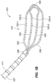
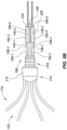
- Fig. 1A is a top view of a high density electrode mapping catheter 101 and Fig. 1B is an isometric side and top view of the high density electrode mapping catheter 101, according to various embodiments of the present disclosure.
- the high density electrode mapping catheter 101 can include a flexible tip portion 110 that forms a flexible array of microelectrodes 102-1, 102-2, 102-3, 102-4.
- microelectrodes 102-1, 102-2, 102-3, 102-4 are referred to in the plural as microelectrodes 102.
- the high density mapping catheter 101 can include more than four microelectrodes, as depicted.
- This planar array (or 'paddle' configuration) of microelectrodes 102 comprises four side-by-side, longitudinally-extending arms 103, 104, 105, 106, which can form a flexible framework on which the microelectrodes 102 are disposed.
- the four microelectrode-carrier arms comprise a first outboard arm 103, a second outboard arm 106, a first inboard arm 104, and a second inboard arm 105, which can be connected via a distal coupler 109. These arms can be laterally separated from each other.
- Each of the four arms can carry a plurality of microelectrodes 102.
- each of the four arms can carry microelectrodes 102 spaced along a length of each of the four arms.
- the high density electrode mapping catheter 101 depicted in Figs. 1A and 1B is depicted as including 18 electrodes (e.g., 5 microelectrodes on first outboard arm 103 and second outboard arm 106 and 4 microelectrodes on first inboard arm 104 and second inboard arm 105), the catheters can include more or fewer than 18 electrodes.
- the first outboard arm 103 and second outboard arm 106 can include more or fewer than 5 microelectrodes and the first inboard arm 104 and second inboard arm 105 can include more or fewer than 4 microelectrodes).
- the microelectrodes 102 can be used in diagnostic, therapeutic, and/or mapping procedures.
- the microelectrodes 102 can be used for electrophysiological studies, pacing, cardiac mapping, and/or ablation.
- the microelectrodes 102 can be used to perform unipolar or bipolar ablation. This unipolar or bipolar ablation can create specific lines or patterns of lesions.
- the microelectrodes 102 can receive electrical signals from the heart, which can be used for electrophysiological studies.
- the microelectrodes 102 can perform a location or position sensing function related to cardiac mapping.
- the high density electrode mapping catheter 101 can include a catheter shaft 107.
- the catheter shaft 107 can include a proximal end and a distal end.
- the distal end can include a connector 108, which can couple the distal end of the catheter shaft 107 to a proximal end of the planar array.
- the catheter shaft 107 can define a catheter shaft longitudinal axis aa, as depicted in Fig. 1A , along which the first outboard arm 103, first inboard arm 104, second inboard arm 105, and second outboard arm 106 can generally extend parallel in relation therewith.
- the catheter shaft 107 can be made of a flexible material, such that it can be threaded through a tortuous vasculature of a patient.
- the catheter shaft 107 can include one or more ring electrodes 111 disposed along a length of the catheter shaft 107.
- the ring electrodes 111 can be used for diagnostic, therapeutic, and/or mapping procedures, in an example.
- the flexible tip portion 110 can be adapted to conform to tissue (e.g., cardiac tissue). For example, when the flexible tip portion 110 contacts tissue, the flexible tip portion 110 can deflect, allowing the flexible framework to conform to the tissue.
- the arms (or the understructure of the arms) comprising the paddle structure (or multi-arm, electrode-carrying, flexible framework) at the distal end of the catheters depicted in Figs. 1A and 1B can be laser cut from a flexible or spring-like material such as Nitinol and/or a flexible substrate, as discussed herein.
- the arms can be formed from a sheet of metal (e.g., Nitinol) with a uniform thickness. Different portions of the arms (or understructure of the arms) can be formed from the sheet (e.g., cut) such that the different portions of the arms have varying widths.
- the construction (including, for example, the length and/or diameter of the arms) and material of the arms can be adjusted or tailored to be created, for example, desired resiliency, flexibility, foldability, conformability, and stiffness characteristics, including one or more characteristics that may vary from the proximal end of a single arm to the distal end of that arm, or between or among the plurality of arms comprising a single paddle structure.
- the foldability of materials such as Nitinol and/or another type of flexible substrate provide the additional advantage of facilitating insertion of the paddle structure into a delivery catheter or introducer, whether during delivery of the catheter into the body or removal of the catheter from the body at the end of a procedure.
- the disclosed catheters are useful to (1) define regional propagation maps of particularly sized areas (e.g., one centimeter square areas) within the atrial walls of the heart; (2) identify complex fractionated atrial electrograms for ablation; (3) identify localized, focal potentials between the microelectrodes for higher electrogram resolution; and/or (4) more precisely target areas for ablation.
- These mapping catheters and ablation catheters are constructed to conform to, and remain in contact with, cardiac tissue despite potentially erratic cardiac motion. Such enhanced stability of the catheter on a heart wall during cardiac motion provides more accurate mapping and ablation due to sustained tissue-electrode contact.
- the catheters described herein may be useful for epicardial and/or endocardial use.
- the planar array embodiments depicted herein may be used in an epicardial procedure where the planar array of microelectrodes is positioned between the myocardial surface and the pericardium.
- the planar array embodiments may be used in an endocardial procedure to quickly sweep and/or analyze the inner surfaces of the myocardium and quickly create high-density maps of the heart tissue's electrical properties.
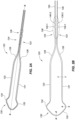
- Fig. 2A is an isometric side and top view of an inboard understructure 120 (also referred to herein as inner understructure) of the high density electrode mapping catheter depicted in Fig. 1A , according to various embodiments of the present disclosure.
- the inboard understructure 120 can be formed from a flexible or spring-like material such as Nitinol and/or a flexible substrate, as discussed herein.
- the inboard understructure can be cut from a planar sheet of material (e.g., planar substrate).
- the inboard understructure 120 can include a first inboard arm understructure 121 and a second inboard arm understructure 122.
- the outboard understructure (also referred to herein as outer understructure) that provides the understructure for the first outboard arm 103 and the second outboard arm 106 can be formed and/or processed in a manner analogous to that discussed in relation to the inboard understructure 120.
- the high density electrode mapping catheter includes additional arms, those arms can be formed and/or processed in a manner analogous to that discussed in relation to the inboard understructure 120.
- discussion is directed towards the inboard understructure 120.
- the inboard understructure 120 can include a first proximal inboard mounting arm 123 and a second proximal inboard mounting arm 124.
- the proximal inboard mounting arms can be inserted into a distal end of the catheter 107 and through the connector 108 and can be used to connect the flexible tip portion 110 to the distal end of the catheter 107.
- the proximal inboard mounting arms can be inserted through a torsional spacer, as discussed herein.
- the inboard understructure 120 can define a tip longitudinal axis, depicted by line bb.
- the inboard understructure 120 can be formed from a continuous element that includes a first rectangular cross-section.
- a rectangular cross-section can include a square cross-section.
- the inboard understructure 120 can include the first proximal inboard mounting arm 123 and second proximal inboard mounting arm 124, which can extend along the longitudinal axis.
- the inboard understructure 120 can include a first inboard arm understructure 121 that extends distally from the first proximal inboard mounting arm 123 and can include a second inboard arm understructure 122 that extends distally from the second proximal inboard mounting arm 124.
- the first inboard arm understructure 121 and the second inboard arm understructure 122 can extend parallel to the tip longitudinal axis bb and to one another.
- a first transition understructure portion 126 can be disposed between the first proximal inboard mounting arm 123 and the first inboard arm understructure 121.
- the first transition understructure portion 126 can be laterally flared away from the tip longitudinal axis bb.
- a second transition understructure portion 127 can be disposed between the second proximal inboard mounting arm 124 and the second inboard arm understructure 122.
- the second transition understructure portion 128 can be laterally flared away from the tip longitudinal axis bb.
- the first transition understructure portion 126 and the second transition understructure portion 128 can be flared away from one another.
- the inboard understructure 120 includes a flared head portion 130 that is connected to distal ends of the first and second inboard arm understructures 121, 122.
- the flared head portion 130 can be formed from a first flared element 132 and a second flared element 134. As the first flared element 132 and the second flared element 134 extend distally, the elements 132, 134 can be laterally flared away from the tip longitudinal axis bb and away from one another, before extending toward the tip longitudinal axis bb and toward one another.
- the first flared element 132 and the second flared element 134 can be connected along the tip longitudinal axis bb.
- the inboard understructure can be symmetrical along either side of the tip longitudinal axis bb.
- the proximal inboard portion of the inboard frame understructure 120 can include the first proximal inboard mounting arm 123 and the second proximal inboard mounting arm 124.
- the proximal inboard portion of the inboard frame understructure 120 can include an inboard frame lock portion 136, which is further discussed in relation to Fig. 2B .
- Fig. 2B depicts a top view of the inboard understructure 120 depicted in Fig. 2A , according to various embodiments of the present disclosure.
- Fig. 2B depicts the inboard frame lock portion 136 of the proximal inboard portion of the inboard frame understructure 120.
- a distal end of the first proximal inboard mounting arm 123 and the second proximal inboard mounting arm 124 can be connected to a proximal end of the first transition understructure portion 126 and the second transition understructure portion 128, respectively.
- the first proximal inboard mounting arm 123 can have a reduced lateral width with respect to the first transition understructure portion 126 and the second proximal inboard mounting arm 124 can have a reduced lateral width with respect to the second transition understructure portion 128.
- the transition understructure portions 126, 128 and the proximal inboard mounting arms 123, 124 can be tapered at a tapered transition area between the two elements, as further depicted in Fig. 2C .
- a proximal end of the inboard frame lock portion 136 can be connected to a proximal tail portion that includes a first proximal tail 148 and a second proximal tail 150.
- the first proximal tail 148 can be connected to the first proximal inboard mounting arm 123 and the second proximal tail 150 can be connected to the second proximal inboard mounting arm 124.
- the proximal inboard mounting arms 123, 124 and the proximal tails 148, 150 can be tapered at a tapered tail transition area between the two elements, as further depicted in Fig. 2C .
- the inboard frame lock portion 136 can include a first pair of inboard frame lock tabs 138-1, 138-2 and a second pair of inboard frame lock tabs 140-1, 140-2.
- the inboard frame lock tabs 138-1, 138-2, 140-1, 140-2 can laterally extend outward from the first proximal inboard mounting arm 123 and the second proximal inboard mounting arm 124.
- first pair of inboard frame lock tabs 138-1, 138-2 can laterally extend from the first proximal inboard mounting arm 123 away from tip longitudinal axis bb; and the second pair of inboard frame lock tabs 140-1, 140-2 can laterally extend from the second proximal inboard mounting arm 124 away from tip longitudinal axis bb.
- Fig. 2C is an enlarged view of an inboard frame lock portion 136 of the inboard understructure 120 depicted in Fig. 2A , according to various embodiments of the present disclosure.
- each of the inboard frame lock tabs can include a distal tab edge 142-1 and a proximal tab edge 142-2.
- the distal tab edge 142-1 and the proximal tab edge 142-2 can be perpendicular to the tip longitudinal axis bb, although not depicted.
- the distal tab edge 142-1 and the proximal tab edge 142-2 can be formed at an angle ⁇ ' with respect to one another.
- the angle ⁇ ' can be in a range from 60 degrees to 10 degrees, in some embodiments. However, the angle ⁇ ' can be less than 10 degrees or greater than 60 degrees in some embodiments. As depicted, the angle ⁇ ' can be 30 degrees.
- a longitudinal length of each of the tabs can be approximately 0.036 inches, although the tabs can have a shorter or longer length.
- the tabs can be of a uniform longitudinal length in some embodiments and/or can be of different longitudinal lengths.
- each of the tabs can have a lateral width of approximately 0.013 inches, although the lateral width of each tab can be greater or smaller.
- the tabs can be longitudinally spaced apart. For example, with respect to the first inboard lock tab 140-1 and the second inboard lock tab 140-2, the longitudinal center of each tab can be longitudinally spaced apart by approximately 0.08 inches, although the tabs can be spaced closer or father apart with respect to one another.
- the transition understructure portions 126, 128 and the proximal inboard mounting arms 123, 124 can include tapered transition areas 144, 146 between the transition understructure portions 126, 128 and the proximal inboard mounting arms 123, 124.
- the tapered transition areas 144, 146 can be tapered in a distal to proximal direction, away from the tip longitudinal axis bb.
- the tapered transition areas 144, 146 can be formed at an angle ⁇ " with respect to one another.
- the angle ⁇ " can be in a range from 10 degrees to 180 degrees, in some embodiments. However, the angle ⁇ " can be less than 10 degrees or greater than 180 degrees in some embodiments. In some embodiments, the angle ⁇ " can be approximately 25 degrees.
- the proximal inboard mounting arms 123, 124 and the proximal tails 148, 150 can include tapered tail transition areas 152, 154 between the proximal inboard mounting arms 123, 124 and the proximal tails 148, 150.
- the tapered tail transition areas 152, 154 can be tapered in a distal to proximal direction, away from the tip longitudinal axis bb.
- the tapered tail transition areas 152, 154 can be formed an angle ⁇ ′′′ with respect to one another.
- the angle ⁇ ′′′ can be in a range from 10 degrees to 180 degrees, in some embodiments. However, the angle ⁇ ′′′ can be less than 10 degrees or greater than 180 degrees in some embodiments. In some embodiments, the angle ⁇ ′′′ can be approximately 25 degrees.
- each portion of the inboard frame understructure 120 ( Fig. 2A, 2B ), including the proximal tails 148, 150, proximal inboard mounting arms 123, 124, inboard arm understructures 121, 122, and flared head portion 130 can be formed from a planar substrate.
- the planar substrate can have a rectangular cross-section, which can be beneficial, as further described herein.
- high density electrode mapping catheters can be assembled using tubular subassemblies for the inboard understructure and the outboard understructure.
- One reason for the use of tubing when assembling the understructures is to allow wire to be threaded through the tubing for connection of each individual microelectrode. This process can be labor and/or cost intensive, since each wire may be individually threaded through the tubing and individually connected with each microelectrode. Further, ensuring that a reliable electrical connection is established between each microelectrode and its wire can be challenging.
- tubing can result in a less predictable deflection of the flexible tip portion since the walls of the tubing may be symmetrical and are not biased to bend in a particular manner.
- Embodiments of the present disclosure can provide for a more predictable deflection of the flexible tip portion 110.
- embodiments of the present disclosure can maintain a lateral spacing between electrodes disposed on the inboard understructure and an outboard understructure, as further discussed herein.
- the inboard understructure 120 (and although not depicted, the outboard understructure) can be formed from a planar piece of material.
- the inboard understructure 120 (and the outboard understructure) can be formed from an understructure with a rectangular and/or square shaped cross-section.
- the inboard understructure 120 and/or the outboard understructure can be a continuous element that is formed from a single unitary piece of material.
- a rectangular cross-section can be defined as a cross-section having a greater width than thickness.
- a rectangular cross-section can include a cross-section having a greater thickness than width.
- a square cross-section can be defined as a cross-section having a same width and thickness.
- Fig. 2D depicts a cross-section of a flared head portion 130 of the inboard understructure 120 depicted in Fig. 2B along line dd, according to various embodiments of the present disclosure.
- the cross-section of the flared head portion 130 can be rectangular, as depicted in Fig. 2D , having a greater width than thickness.
- the cross-section can be square, having a same width and thickness.
- a thickness at a longitudinal apex of the flared head portion 130 defined by line dt can be in a range from 0.0045 to 0.0065 inches.
- the thickness at the longitudinal apex of the flared head portion 130 can be approximately 0.006 inches.
- a longitudinal width (e.g., width extending along the longitudinal axis bb) at the longitudinal apex of the flared head portion 130 defined by line d w can be in a range from 0.007 to 0.009 inches. In some embodiments, the longitudinal width at the longitudinal apex of the flared head portion 130 can be approximately 0.008 inches.
- Fig. 2E depicts a cross-section of a flared head portion 130 of the inboard understructure 120 depicted in Fig. 2B along line ee, according to various embodiments of the present disclosure.
- the cross-section at a lateral apex of the flared distal head portion 130 can be square, as depicted in Fig. 2E , having a same width and thickness.
- the cross-section at the lateral apex of the flared distal head portion 130 can be rectangular, having a greater width than thickness.
- a thickness at the lateral apex of the flared head portion 130 defined by line et can be in a range from 0.0045 to 0.0065 inches.
- the thickness at the lateral apex of the flared head portion 130 can be approximately 0.006 inches.
- a lateral width (e.g., width extending transverse to the longitudinal axis bb) at the lateral apex of the flared head portion 130 defined by line e w can be in a range from 0.005 to 0.007 inches.
- the lateral width at the lateral apex of the flared head portion 130 can be approximately 0.006 inches.
- Fig. 2F depicts a cross-section of a first inboard arm understructure 121 of the inboard understructure 120 depicted in Fig. 2B along line ff, according to various embodiments of the present disclosure.
- the cross-section of the first inboard arm understructure 121 can be rectangular, as depicted in Fig. 2F , having a greater width than thickness.
- the cross-section can be square, having a same width and thickness.
- a thickness at the first inboard arm understructure 121 defined by line f t can be in a range from 0.0045 to 0.0065 inches. In some embodiments, the thickness at the first inboard arm understructure 121 can be approximately 0.006 inches.
- a lateral width at the first inboard arm understructure 121 defined by line f w can be in a range from 0.0125 to 0.0135 inches. In some embodiments, the lateral width at the lateral apex of the flared head portion 130 can be approximately 0.013 inches.
- the second inboard arm understructure 122 can be of the same dimensions as the first inboard arm understructure 121. Accordingly, in some embodiments, the inboard understructure 120 can have a uniform thickness and a varying width.
- Fig. 3A is a top view of an outboard understructure 170 (also referred to herein as outer understructure) of a high density electrode mapping catheter in Fig. 1A , according to various embodiments of the present disclosure.
- the outboard understructure 170 can be formed from a flexible or spring-like material such as Nitinol and/or a flexible substrate, as previously discussed with respect to the inboard understructure.
- the outboard understructure 170 can include a first outboard arm understructure 172 and a second outboard arm understructure 174.
- the outboard understructure 170 can include a first proximal inboard mounting arm 176 and a second proximal inboard mounting arm 178.
- the proximal inboard mounting arms 176, 178 can be inserted into a distal end of the catheter 107 ( Fig. 1A , 1B ) and can be used to connect the flexible tip portion 110 ( Fig. 1A , 1B ) to the distal end of the catheter 107.
- the proximal outboard mounting arms 176, 178 can be inserted through a torsional spacer, as discussed herein.
- the outboard understructure 170 can define a tip longitudinal axis, depicted by line b'b'.
- the outboard understructure 170 can be formed from a continuous element that includes a first rectangular cross-section.
- the outboard understructure 170 can include the first proximal outboard mounting arm 176 and second proximal outboard mounting arm 178, which can extend along the tip longitudinal axis.
- the outboard understructure 170 can include a first outboard arm understructure 172 that extends distally from the first proximal inboard mounting arm 176 and can include a second outboard arm understructure 174 that extends distally from the second proximal outboard mounting arm 178.
- the first outboard arm understructure 172 and the second outboard arm understructure 174 can extend parallel to the tip longitudinal axis b'b' and to one another.
- a first outboard transition understructure portion 180 can be disposed between the first proximal outboard mounting arm 176 and the first outboard arm understructure 172.
- the first outboard transition understructure portion 180 can be laterally flared away from the tip longitudinal axis b'b'.
- a second outboard transition understructure portion 181 can be disposed between the second proximal outboard mounting arm 178 and the second outboard arm understructure 174.
- the second outboard transition understructure portion 181 can be laterally flared away from the tip longitudinal axis b'b'.
- the first outboard transition understructure portion 180 and the second outboard transition understructure portion 181 can be flared away from one another.
- the outboard understructure 170 includes a head portion 182 that is connected to distal ends of the first and second outboard arm understructures 172, 174.
- the head portion 182 can be formed from a first tapered element 184 and a second tapered element 186 that each extend distally toward the tip longitudinal axis b'b' and converge at the longitudinal axis b'b'.
- the outboard understructure 170 can be symmetrical along either side of the tip longitudinal axis b'b'.
- the proximal outboard portion of the inboard frame understructure 170 can include the first proximal outboard mounting arm 176 and the second proximal outboard mounting arm 178.
- the proximal outboard portion of the outboard frame understructure 170 can include an outboard frame lock portion 188, which is further discussed in relation to Fig. 3B .
- a distal end of the first proximal outboard mounting arm 176 and the second proximal outboard mounting arm 178 can be connected to a proximal end of the first outboard transition understructure portion 180 and the second outboard transition understructure portion 181, respectively.
- the first proximal outboard mounting arm 176 can have a reduced lateral width with respect to the first outboard transition understructure portion 180 and the second proximal outboard mounting arm 178 can have a reduced lateral width with respect to the second outboard transition understructure portion 181.
- the outboard transition understructure portions 180, 181 and the proximal outboard mounting arms 176, 178 can be tapered at an outboard tapered transition area between the two elements, as further depicted in Fig. 3B .
- a proximal end of the outboard frame lock portion 188 can be connected to a proximal outboard tail portion that includes a first proximal outboard tail 189 and a second proximal outboard tail 190.
- the first proximal outboard tail 189 can be connected to the first proximal outboard mounting arm 176 and the second proximal outboard tail 190 can be connected to the second proximal outboard mounting arm 178.
- the proximal outboard mounting arms 176, 178 and the proximal outboard tails 189, 190 can be tapered at a tapered outboard tail transition area between the two elements, as further depicted in Fig. 3B .
- the outboard frame lock portion 188 can include a first pair of outboard frame lock tabs 192-1, 192-2 and a second pair of outboard frame lock tabs 194-1, 194-2.
- the outboard frame lock tabs 192-1, 192-2, 194-1, 194-2 can laterally extend inward from the first proximal outboard mounting arm 176 and the second proximal inboard mounting arm 178.
- first pair of outboard frame lock tabs 192-1, 192-2 can laterally extend from the first proximal inboard mounting arm 176 toward the tip longitudinal axis b'b'; and the second pair of outboard frame lock tabs 194-1, 194-2 can laterally extend from the second proximal inboard mounting arm 178 toward the tip longitudinal axis b'b'.
- Fig. 3B is an enlarged view of an outboard frame lock portion 188 of the outboard understructure 170 depicted in Fig. 3A , according to various embodiments of the present disclosure.
- each of the outboard frame lock tabs can include a distal tab edge 200-1 and a proximal tab edge 200-2.
- the distal tab edge 200-1 and the proximal tab edge 200-2 can be perpendicular to the tip longitudinal axis b'b', although not depicted.
- the distal tab edge 200-1 and the proximal tab edge 200-2 can be formed at an angle ⁇ A with respect to one another.
- the angle ⁇ A can be in a range from 60 degrees to 10 degrees, in some embodiments. However, the angle ⁇ ' can be less than 10 degrees or greater than 60 degrees in some embodiments. As depicted, the angle ⁇ ' can be 30 degrees. In some embodiments, the angle ⁇ A can be the same as the angle ⁇ ', to ensure that inboard frame lock portion 136 fits together with the outboard frame lock portion 188.
- a first pair of lock grooves 196-1, 196-2 and a second pair of lock grooves 198-1, 198-2 can be formed in the outboard frame lock portion 188.
- the lock grooves can be formed on the inside (e.g., side towards the tip longitudinal axis b'b') of each first and second proximal outboard mounting arms 178.
- the first and second pairs of inboard frame lock tabs 138-1, 138-2, 140-1, 140-2 ( Fig. 2B , 2C ) can be inserted into respective ones of the lock grooves 196-1, 196-2, 198-1, 198-2, as further discussed herein.
- the transition understructure portions 180, 181 and the proximal outboard mounting arms 176, 187 can include tapered transition areas 202, 204 between the transition understructure portions 180, 181 and the proximal inboard mounting arms 176, 178.
- the tapered transition areas 202, 204 can be tapered in a distal to proximal direction, toward the tip longitudinal axis b'b'.
- the tapered transition areas 202, 204 can be formed at an angle ⁇ B with respect to one another.
- the angle ⁇ B can be in a range from 10 degrees to 180 degrees, in some embodiments. However, the angle ⁇ B can be less than 10 degrees or greater than 180 degrees in some embodiments. In some embodiments, the angle ⁇ B can be approximately 25 degrees.
- the proximal outboard mounting arms 176, 178 and the proximal outboard tails 189, 190 can include tapered tail transition areas 206, 208 between the proximal outboard mounting arms 176, 178 and the proximal outboard tails 189, 190.
- the tapered tail transition areas 206, 208 can be tapered in a distal to proximal direction, toward the tip longitudinal axis b'b'.
- the tapered tail transition areas 206, 208 can be formed at an angle ⁇ C with respect to one another.
- the angle ⁇ C can be in a range from 10 degrees to 180 degrees, in some embodiments. However, the angle ⁇ C can be less than 10 degrees or greater than 180 degrees in some embodiments. In some embodiments, the angle ⁇ C can be approximately 46 degrees.
- each portion of the outboard frame understructure 170 can be formed from a planar substrate.
- the planar substrate can have a rectangular cross-section, which can be beneficial, as further described herein.
- high density electrode mapping catheters can be assembled using tubular subassemblies for the inboard understructure and the outboard understructure.
- use of tubing can result in a less predictable deflection of the flexible tip portion since the walls of the tubing may be symmetrical and are not biased to bend in a particular manner.
- Embodiments of the present disclosure can provide for a more predictable deflection of the flexible tip portion 110 and the inboard understructure 120 ( Figs 2A, 2B ) and the outboard understructure 170.
- the outboard understructure 170 can be formed from a planar piece of material.
- the outboard understructure 170 can be formed from an understructure with a rectangular and/or square shaped cross-section.
- the outboard understructure 170 can be a continuous element that is formed from a single unitary piece of material.
- Fig. 3C depicts a cross-section of a head portion 182 of the outboard understructure 170 depicted in Fig. 3B along line gg, according to various embodiments of the present disclosure.
- a thickness at a longitudinal apex of the head portion 182 defined by line gt can be in a range from 0.0045 to 0.0065 inches.
- the thickness at the longitudinal apex of the flared head portion 130 can be approximately 0.006 inches.
- a longitudinal width (e.g., width extending along the longitudinal axis b'b') at the longitudinal apex of the head portion 182 defined by line g w can be in a range from 0.0075 to 0.0085 inches.
- the longitudinal width at the longitudinal apex of the flared head portion 130 can be approximately 0.008 inches.
- Fig. 3D depicts a cross-section of the first outboard arm understructure 172 of the outboard understructure 170 depicted in Fig. 3A along line hh, according to various embodiments of the present disclosure.
- a thickness at the first outboard arm understructure 172 defined by line h t can be in a range from 0.0045 to 0.0065 inches. In some embodiments, the thickness at the first outboard arm understructure 172 can be approximately 0.006 inches.
- a lateral width (e.g., width extending transverse to the longitudinal axis b'b') at the first outboard arm understructure 172 defined by line h w can be in a range from 0.0125 to 0.0135 inches. In some embodiments, the lateral width at the first outboard arm understructure 172 can be approximately 0.013 inches.
- the second outboard arm understructure 174 can have a similar construction as discussed in relation to the first outboard arm understructure 172.
- Fig. 4 depicts the inboard understructure 120 depicted in Fig. 2A and the outboard understructure 170 depicted in Fig. 3A with interlocking inboard frame lock portion 136 and outboard frame lock portion 188, according to various embodiments of the present disclosure.
- the inboard understructure 120 and the outboard understructure 170 include those features previously discussed in relation to Figs. 2A to 3D .
- the inboard frame lock portion 136 is depicted as interlocking with the outboard frame lock portion 188.
- the inboard frame lock tabs 138-1, 138-2, 140-1, 140-2 are disposed in the lock grooves 196-1, 196-2, 198-1, 198-2 and adjacent to the outboard frame lock tabs 192-1, 192-2, 194-1, 194-2.
- This can create an interlocking fit between the inboard frame lock portion 136 and the outboard frame lock portion 188.
- the interlocking fit can prevent longitudinal movement of the inboard understructure 120 with respect to the outboard understructure 170, in some embodiments.
- the inboard frame lock portion 136 can be disposed in the outboard frame lock portion 188 such that a top surface of the inboard frame lock portion 136 is flush with a top surface of the outboard frame lock portion 188; and a bottom surface of the inboard frame lock portion 136 is flush with a bottom surface of the outboard frame lock portion 188.
- the first and second outboard transition understructure portions 126, 128 can be formed at descending angles in a distal to proximal direction and the understructure forming the head portion 182 and flared head portion 130 can be formed at ascending angles in a distal to proximal direction.
- This can increase an ease of delivery and withdrawal through a sheath and also during manufacturing of the electrodes that are disposed on the inboard understructure 120 and/or the outboard understructure 170.
- electrodes can be slid over the understructure in a proximal to distal direction.
- the angle of the outboard transition understructure can allow for easier sliding of the electrodes over the understructure.
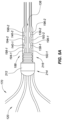
- Fig. 5A depicts the inboard understructure 120 depicted in Fig. 2A and the outboard understructure 170 depicted in Fig. 3A with interlocking inboard frame lock portion 136 and outboard frame lock portion 188 and a connector 212, according to various embodiments of the present disclosure.
- a gap is depicted between the inboard frame lock portion 136 and the outboard frame lock portion 188.
- a connector 212 can be disposed at a distal end of the inboard frame lock portion 136 and outboard frame lock portion 188, as depicted.
- the inboard understructure 120 and the outboard understructure 170 can longitudinally extend through the connector 212.
- the connector 212 can include a connector head portion 214 and a mount portion 216 and can be formed from a polymer or metal.
- the mount portion 216 can be cylindrical in shape and can be sized to be inserted into a distal end of a catheter shaft.
- an adhesive can be applied between the catheter shaft and the mount portion 216 and/or a mechanical connector can be used to secure the catheter shaft to the mount portion 216.
- a series of circumferential grooves can extend around a circumference of the mount portion 216. The circumferential grooves can provide an area for an adhesive to collect when connecting the connector 212 to the catheter shaft.
- the connector head portion 214 can have an outer diameter that is greater than the mount portion 216 and can be equal to an outer diameter of a catheter shaft.
- a distal end of the head portion 214 can be dome shaped, as depicted, to form an atraumatic tip.
- Fig. 5B depicts the inboard understructure 120 and outboard understructure 170 depicted in Fig. 5A with tubing 220, 222 disposed around the interlocking inboard frame lock portion 136 and outboard frame lock portion 188, according to various embodiments of the present disclosure.
- a first section of tubing 220 and a second section of tubing 222 can each be disposed around the interlocking portions of the inboard frame lock portion 136 and outboard frame lock portion 188.
- the interlocking portions of the inboard frame lock portion 136 and the outboard frame lock portion 188 disposed within the first and second section of tubing 220, 222 is depicted in phantom.
- first section of tubing 220 and the second section of tubing 222 can include an inner diameter that is the same or larger than a lateral width of the interlocking portions of the inboard frame lock portion 136 and the outboard frame lock portion 188.
- the first section of tubing 220 and the second section of tubing 222 can be slid longitudinally over a proximal portion of the interlocking portions of the inboard frame lock portion 136 and the outboard frame lock portion 188, such that the interlocking portions of the inboard frame lock portion 136 and the outboard frame lock portion 188 are disposed in respective lumens of the first and second sections of tubing 220, 222.
- first and second sections of tubing 220, 222 are depicted as extending over the proximal portion of the interlocking portions of the inboard frame lock portion 136 and the outboard frame lock portion 188, the first and second section of tubing 220, 222 can extend more distally.
- the first and second section of tubing 220, 222 can extend to the proximal end of the coupler 212.
- the lumens of the first and second sections of tubing 220, 222 can be filled with an adhesive to secure the interlocking portions of the inboard frame lock portion 136 and the outboard frame lock portion 188.
- the first and second sections of tubing 220, 222 can be heat shrink tubing, which can be heated and shrunk to secure the interlocking portions of the inboard frame lock portion 136 and the outboard frame lock portion 188.
- Fig. 6 depicts an isometric side and top view of a high density electrode mapping catheter 230 being deflected, according to various embodiments of the present disclosure.
- the high density electrode mapping catheter includes a flexible tip portion 232 that forms a flexible array of microelectrodes 334, which is disposed at a distal end of a catheter shaft 228.
- This planar array (or 'paddle' configuration) of microelectrodes 234 comprises four side-by-side, longitudinally-extending arms 236, 238, 240, 242, which can form a flexible framework on which the microelectrodes 234 are disposed.
- the four microelectrode-carrier arms comprise a first outboard arm 236, a second outboard arm 242, a first inboard arm 238, and a second inboard arm 240. These arms can be laterally separated from each other.
- the inboard portion of the flexible tip 232 can include a flared head portion 244 and the outboard portion of the flexible tip 232 can include a head portion 246.
- the first outboard arm 236 and the second outboard arm 242 can include an outboard understructure and the first inboard arm 238 and the second inboard arm 240 can include an inboard understructure, as previously discussed.
- the first and second inboard arms 238, 240, as well as the flared head portion 244, can include a first and second inboard arm understructure that is formed from an element that includes a rectangular cross-section and the first and second outboard arms 236, 242, as well as the head portion 246, can include a first and second outboard arm understructure that is formed from an element that includes a rectangular cross-section, as previously discussed herein.
- the flexible tip portion 232 can include a first outboard transition portion 248 and a second outboard transition portion 254.
- the flexible tip portion 232 can include a first inboard transition portion 250 and a second inboard transition portion 252.
- the understructure that forms the flared head portion 244 can have a reduced cross-sectional width in relation to the understructure that forms the inboard arms 238, 240.
- the understructure that forms the head portion 246 can have a reduced cross-sectional width in relation to the understructure that forms the outboard arms 236, 242.
- This reduced cross-sectional width of the understructure forming the flared head portion 244 and the head portion 246 can increase a resiliency of the head portions 244, 246 and cause the head portions 244, 246 to be less traumatic to cardiac tissue.
- the head portions can have an increased flexibility and a reduced amount of force can be required to deflect the head portions 244, 246, providing for an atraumatic design.
- first outboard arm 236, second outboard arm 242, first outboard transition portion 248, and second outboard transition portion 254 can be formed from an understructure that has an increased cross-sectional width in relation to the understructure that forms the head portion 246.
- first inboard arm 238, second inboard arm 240, first inboard transition portion 250, and second inboard transition portion 252 can be formed from an understructure that has an increased cross-sectional width in relation to the understructure that forms the flared head portion 244.
- the increased cross-sectional width of the understructure that forms the inboard and outboard arms, as well as the inboard and outboard transition portions can provide for a more gradual bend of the flexible tip portion 232 located proximal to the flared head portion 244 and the head portion 246.
- the more gradual bend can be beneficial in making homogeneous (e.g. uniform) cardiac tissue contact with all of the electrodes disposed on the inboard and outboard arms and/or the inboard and outboard transition portions.
- the understructure that forms each component of the flexible tip portion 232 includes a rectangular cross-section, the lateral spacing between each one of the microelectrodes disposed on the flexible tip portion 232 can be maintained when various lateral forces (e.g., pinch) are applied to the flexible tip portion, which can be encountered in relation to various anatomical conditions.
- various lateral forces e.g., pinch
- an electrode spacing can be maintained even when a lateral force is applied to the flexible tip portion 110 in the direction of arrows 112-1, 112-2.
- the arms when a lateral force is applied to the inboard and/or outboard arms, the arms can bend inward toward the longitudinal axis aa.
- the outboard arms 103, 106 included a tubular understructure, the outboard arms 103, 106 would be pushed laterally inward toward the longitudinal axis and towards the inboard arms 104, 105 in response to a force being applied in the direction of arrows 112-1, 112-2.
- This can reduce a spacing between the microelectrodes disposed on the outboard arms and the microelectrodes disposed on the inboard arms, thus causing interference between the microelectrodes.
- embodiments of the present disclosure can maintain the spacing between the inboard arms and the outboard arms, as well as the microelectrodes disposed on the inboard arms and the outboard arms.
- the understructure that forms the inboard arms 104, 105 and the outboard arms 103, 106 can have a rectangular cross-section, as discussed in relation to Figs. 2A to 3D .
- the understructure that forms the inboard arms 104, 105 and the outboard arms 103, 106 can have an increased lateral width versus a lateral width of the understructure that forms the head portions.
- a dimension of the lateral width can be greater than a dimension of the thickness of the understructure that forms the inboard arms 104, 105 and the outboard arms 103, 106.
- a lateral spacing can be maintained between a first microelectrode 102-1 disposed on the first outboard arm 103 and a third microelectrode 102-3 disposed on the first inboard arm 104 in the presence of a lateral force in the direction of arrows 112-1, 112-2.
- a lateral spacing can be maintained between a second microelectrode 102-2 disposed on the first outboard arm 103 and a fourth microelectrode 102-4 disposed on the first inboard arm 104 in the presence of a lateral force in the direction of arrows 112-1, 112-2.
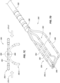
- Fig. 7A depicts a front view of a high density electrode mapping catheter 260 in a first deflection state 262-1 and a second deflection state 262-2, according to various embodiments of the present disclosure.
- the high density electrode mapping catheter 260 includes an outboard portion 264 formed from an outboard understructure.
- the outboard understructure can be formed from an element with a rectangular cross-section, as discussed herein.
- the high density electrode mapping catheter 260 can include a connector 266 disposed on the distal end of a catheter shaft 282 (depicted in Figs.
- the outboard portion 264 can be in a first deflection state 262-1 (e.g., a natural deflection state), extending laterally with respect to a longitudinal axis of the high density electrode mapping catheter 260.
- a lateral force is applied to the outboard portion 264 in the direction of arrows 270-1, 270-2, the outboard portion can deflect upward into a second deflection state 262-2, depicted in phantom.
- the outboard portion 264 can deflect upward into the second deflection state 262-2, rather than deflecting laterally inward toward a longitudinal axis of the high density electrode mapping catheter 260.
- Fig. 7B depicts an isometric, side, front, and top view of the high density electrode mapping catheter 260 in the second deflection state 262-2 in Fig. 7A , according to various embodiments of the present disclosure.
- the high density electrode mapping catheter 260 includes those features discussed in relation to Fig. 7A , for example, the high density electrode mapping catheter 260 includes the outboard portion 264, the inboard portion 280, distal coupler 268, connector 266 and catheter shaft 282. As depicted, the outboard portion 264 and the inboard portion 280 can be deflected upward in response to a lateral force being subjected to the high density mapping catheter 260 (e.g., the outboard portion 264 and/or inboard portion 280).
- first and second outboard arms 282, 288 can deflect upward instead of deflecting laterally inward toward a longitudinal axis of the high density electrode mapping catheter 260.
- Fig. 7C depicts a front view of the high density electrode mapping catheter 260 depicted in Figs. 7A and 7B in the first deflection state 262-1 and a third deflection state 262-3, according to various embodiments of the present disclosure.
- the high density electrode mapping catheter 260 includes the outboard portion 264 formed from an outboard understructure, connector 266 disposed on the distal end of the catheter shaft 282 (depicted in Fig. 7B and 7D ), as well as the distal coupler 268 that couples an inboard portion 280 (depicted in Fig. 7B and 7D ) with the outboard portion 264.
- the understructure of the outboard portion 264 can be in a first deflection state 262-1 (e.g., a natural deflection state), extending laterally with respect to a longitudinal axis of the high density electrode mapping catheter 260.
- a first deflection state 262-1 e.g., a natural deflection state
- the outboard portion 264 can deflect downward into a third deflection state 262-3, depicted in phantom.
- the outboard portion 264 can deflect downward into the third deflection state 262-3, rather than deflecting laterally inward toward a longitudinal axis of the high density electrode mapping catheter 260.
- a deciding factor associated with whether the outboard portion 264 or inboard portion 280 of the high density electrode mapping catheter 260 will deflect downward or upward can be associated with an angle at which the lateral force is applied to the outboard portion 264 and/or inboard portion 280.
- Fig. 7D depicts an isometric, side, front, and top view of the high density electrode mapping catheter 260 in the third deflection state 262-3 in Fig. 7C , according to various embodiments of the present disclosure.
- the high density electrode mapping catheter 260 includes those features discussed in relation to Fig. 7C , for example, the high density electrode mapping catheter 260 includes the outboard portion 264, the inboard portion 280, distal coupler 268, connector 266 and catheter shaft 282. As depicted, the outboard portion 264 and the inboard portion 280 can be deflected downward in response to a lateral force being subjected to the high density mapping catheter 260 (e.g., the outboard portion 264 and/or inboard portion 280).
- the understructure that forms the first outboard arm 282 and second outboard arm 288 and the understructure that forms the first inboard arm 284 and second inboard arm 286 of the high density electrode mapping catheter 260 have a rectangular cross-section (e.g., have an increased lateral width versus thickness)
- the first and second outboard arms 282, 288 can deflect downward instead of deflecting laterally inward toward a longitudinal axis of the high density electrode mapping catheter 260. This can maintain a spacing between microelectrodes disposed on the inboard and outboard arms.
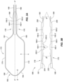
- Fig. 8 depicts a top view of a high density electrode mapping catheter 300 with a flexible tip portion 304 in a collapsed state, according to various embodiments of the present disclosure.
- the high density electrode mapping catheter 300 can include a catheter shaft 302.
- the catheter shaft 302 can include a proximal end and a distal end.
- the distal end can include a connector 306, which can couple the distal end of the catheter shaft 302 to a proximal end of the flexible tip portion 304 (e.g., planar array).
- the flexible tip portion 304 can include an outboard portion that includes a first outboard arm 308, second outboard arm 214, and head portion 318 and can include an inboard portion that includes a first inboard arm 310 and second inboard arm 312 and a flared head portion 316.
- the head portion 318 and the flared head portion 316 can be connected at their respective distal ends via a distal coupler 320, in some embodiments.
- the flexible tip portion 304 is in a stored state.
- the flexible tip portion 304 can be in such a state when it is stored in a sheath for introduction into a body, in an example.
- the outboard portion and inboard portion of the flexible tip portion 304 can be laterally compressed toward a longitudinal axis of the high density electrode mapping catheter 300.
- the outboard portion and inboard portion of the flexible tip portion 304 can be laterally compressed by the inner walls of the sheath.
- the flared head portion 316 of the inboard portion can be straightened as the inboard portion and the outboard portion are laterally compressed toward the longitudinal axis of the flexible tip portion 304.
- a hook can be formed in the distal end of the flexible tip portion 304.
- Embodiments of the present disclosure can include for the flared head portion 316, which can provide for a slack portion, which can be lengthened when the inboard portion and the outboard portion are laterally compressed.
- the flared distal head e.g., spade shaped portion
- the flared distal head can compensate for the extra length needed to match the outer frame total length when folded during delivery and/or withdrawal through the sheath, which can prevent the hook from forming.
- proximal and distal may be used throughout the specification with reference to a clinician manipulating one end of an instrument used to treat a patient.
- proximal refers to the portion of the instrument closest to the clinician and the term “distal” refers to the portion located furthest from the clinician.
- distal refers to the portion located furthest from the clinician.
- spatial terms such as “vertical,” “horizontal,” “up,” and “down” may be used herein with respect to the illustrated embodiments.
- surgical instruments may be used in many orientations and positions, and these terms are not intended to be limiting and absolute.
- joinder references do not necessarily infer that two elements are directly connected and in fixed relationship to each other. It is intended that all matter contained in the above description or shown in the accompanying drawings shall be interpreted as illustrative only and not limiting. Changes in detail or structure may be made without departing from the spirit of the disclosure as defined in the appended claims.
Landscapes
- Health & Medical Sciences (AREA)
- Life Sciences & Earth Sciences (AREA)
- Surgery (AREA)
- Engineering & Computer Science (AREA)
- Public Health (AREA)
- Veterinary Medicine (AREA)
- Biomedical Technology (AREA)
- Heart & Thoracic Surgery (AREA)
- Medical Informatics (AREA)
- Molecular Biology (AREA)
- Physics & Mathematics (AREA)
- Animal Behavior & Ethology (AREA)
- General Health & Medical Sciences (AREA)
- Pathology (AREA)
- Biophysics (AREA)
- Cardiology (AREA)
- Plasma & Fusion (AREA)
- Nuclear Medicine, Radiotherapy & Molecular Imaging (AREA)
- Otolaryngology (AREA)
- Physiology (AREA)
- Measurement And Recording Of Electrical Phenomena And Electrical Characteristics Of The Living Body (AREA)
- Surgical Instruments (AREA)
- Media Introduction/Drainage Providing Device (AREA)
Applications Claiming Priority (5)
| Application Number | Priority Date | Filing Date | Title |
|---|---|---|---|
| US201562244630P | 2015-10-21 | 2015-10-21 | |
| EP16858337.5A EP3340917B1 (fr) | 2015-10-21 | 2016-10-21 | Cathéter de cartographie à électrodes haute densité |
| EP23157677.8A EP4205685B1 (fr) | 2015-10-21 | 2016-10-21 | Cathéter de cartographie d'électrode à haute densité |
| EP20217594.9A EP3834759B1 (fr) | 2015-10-21 | 2016-10-21 | Cathéter de cartographie à électrodes haute densité |
| PCT/US2016/058205 WO2017070531A1 (fr) | 2015-10-21 | 2016-10-21 | Cathéter de cartographie à électrodes haute densité |
Related Parent Applications (4)
| Application Number | Title | Priority Date | Filing Date |
|---|---|---|---|
| EP20217594.9A Division EP3834759B1 (fr) | 2015-10-21 | 2016-10-21 | Cathéter de cartographie à électrodes haute densité |
| EP23157677.8A Division EP4205685B1 (fr) | 2015-10-21 | 2016-10-21 | Cathéter de cartographie d'électrode à haute densité |
| EP23157677.8A Division-Into EP4205685B1 (fr) | 2015-10-21 | 2016-10-21 | Cathéter de cartographie d'électrode à haute densité |
| EP16858337.5A Division EP3340917B1 (fr) | 2015-10-21 | 2016-10-21 | Cathéter de cartographie à électrodes haute densité |
Publications (2)
| Publication Number | Publication Date |
|---|---|
| EP4417112A2 true EP4417112A2 (fr) | 2024-08-21 |
| EP4417112A3 EP4417112A3 (fr) | 2024-11-13 |
Family
ID=58558109
Family Applications (4)
| Application Number | Title | Priority Date | Filing Date |
|---|---|---|---|
| EP20217594.9A Active EP3834759B1 (fr) | 2015-10-21 | 2016-10-21 | Cathéter de cartographie à électrodes haute densité |
| EP16858337.5A Active EP3340917B1 (fr) | 2015-10-21 | 2016-10-21 | Cathéter de cartographie à électrodes haute densité |
| EP23157677.8A Active EP4205685B1 (fr) | 2015-10-21 | 2016-10-21 | Cathéter de cartographie d'électrode à haute densité |
| EP24186941.1A Pending EP4417112A3 (fr) | 2015-10-21 | 2016-10-21 | Cathéter de cartographie d'électrode à haute densité |
Family Applications Before (3)
| Application Number | Title | Priority Date | Filing Date |
|---|---|---|---|
| EP20217594.9A Active EP3834759B1 (fr) | 2015-10-21 | 2016-10-21 | Cathéter de cartographie à électrodes haute densité |
| EP16858337.5A Active EP3340917B1 (fr) | 2015-10-21 | 2016-10-21 | Cathéter de cartographie à électrodes haute densité |
| EP23157677.8A Active EP4205685B1 (fr) | 2015-10-21 | 2016-10-21 | Cathéter de cartographie d'électrode à haute densité |
Country Status (5)
| Country | Link |
|---|---|
| US (3) | US10362954B2 (fr) |
| EP (4) | EP3834759B1 (fr) |
| JP (2) | JP6641003B2 (fr) |
| CN (2) | CN111657866B (fr) |
| WO (1) | WO2017070531A1 (fr) |
Cited By (4)
| Publication number | Priority date | Publication date | Assignee | Title |
|---|---|---|---|---|
| US12551656B2 (en) | 2017-07-07 | 2026-02-17 | St. Jude Medical, Cardiology Division, Inc. | Layered high density electrode mapping catheter |
| US12551658B2 (en) | 2022-03-25 | 2026-02-17 | St. Jude Medical, Cardiology Division, Inc. | Steerable introducer with slide block divider |
| US12575877B2 (en) | 2018-04-05 | 2026-03-17 | St. Jude Medical, Cardiology Division, Inc. | High density electrode mapping catheter |
| US12588851B2 (en) | 2018-03-13 | 2026-03-31 | St. Jude Medical, Cardiology Division, Inc. | Variable density mapping catheter |
Families Citing this family (26)
| Publication number | Priority date | Publication date | Assignee | Title |
|---|---|---|---|---|
| CN110833455B (zh) * | 2013-10-25 | 2023-02-28 | 直观外科手术操作公司 | 带有嵌入式致动导管的柔性器械 |
| US9820664B2 (en) | 2014-11-20 | 2017-11-21 | Biosense Webster (Israel) Ltd. | Catheter with high density electrode spine array |
| US9949656B2 (en) | 2015-06-29 | 2018-04-24 | Biosense Webster (Israel) Ltd. | Catheter with stacked spine electrode assembly |
| US10537259B2 (en) | 2015-06-29 | 2020-01-21 | Biosense Webster (Israel) Ltd. | Catheter having closed loop array with in-plane linear electrode portion |
| US10575742B2 (en) | 2015-06-30 | 2020-03-03 | Biosense Webster (Israel) Ltd. | Catheter having closed electrode assembly with spines of uniform length |
| CN111657866B (zh) * | 2015-10-21 | 2023-10-20 | 圣犹达医疗用品心脏病学部门有限公司 | 高密度电极标测导管 |
| CN114668490B (zh) | 2015-10-21 | 2025-10-03 | 圣犹达医疗用品心脏病学部门有限公司 | 高密度电极标测导管 |
| CN109310469B (zh) | 2016-05-03 | 2021-07-23 | 圣犹达医疗用品心脏病学部门有限公司 | 冲洗高密度电极导管 |
| US11786705B2 (en) | 2016-10-24 | 2023-10-17 | St. Jude Medical, Cardiology Division, Inc. | Catheter insertion devices |
| US11172858B2 (en) | 2016-10-28 | 2021-11-16 | St. Jude Medical, Cardiology Division, Inc. | Flexible high-density mapping catheter |
| JP7329442B2 (ja) | 2017-01-19 | 2023-08-18 | セント・ジュード・メディカル,カーディオロジー・ディヴィジョン,インコーポレイテッド | シースの可視化 |
| US11647935B2 (en) | 2017-07-24 | 2023-05-16 | St. Jude Medical, Cardiology Division, Inc. | Masked ring electrodes |
| US10702178B2 (en) | 2017-10-13 | 2020-07-07 | St. Jude Medical, Cardiology Division, Inc. | Catheter with high-density mapping electrodes |
| EP4241819B1 (fr) | 2017-11-28 | 2026-02-25 | St. Jude Medical, Cardiology Division, Inc. | Cathéter extensible ajustable |
| JP7499702B2 (ja) | 2018-05-21 | 2024-06-14 | セント・ジュード・メディカル,カーディオロジー・ディヴィジョン,インコーポレイテッド | 高周波アブレーション及び直流電気穿孔カテーテル |
| US12156979B2 (en) | 2018-05-21 | 2024-12-03 | St. Jude Medical, Cardiology Division, Inc. | Deflectable catheter shaft with pullwire anchor feature |
| WO2020039392A2 (fr) | 2018-08-23 | 2020-02-27 | St. Jude Medical, Cardiology Division, Inc. | Cathéter de cartographie à électrodes haute densité incurvées |
| WO2020065587A2 (fr) | 2018-09-27 | 2020-04-02 | St. Jude Medical, Cardiology Division, Inc. | Ballonnet de cartographie uniforme |
| US11918762B2 (en) | 2018-10-03 | 2024-03-05 | St. Jude Medical, Cardiology Division, Inc. | Reduced actuation force electrophysiology catheter handle |
| US11850051B2 (en) | 2019-04-30 | 2023-12-26 | Biosense Webster (Israel) Ltd. | Mapping grid with high density electrode array |
| US12232874B2 (en) | 2020-05-29 | 2025-02-25 | Biosense Webster (Israel) Ltd. | Electrode apparatus for diagnosis of arrhythmias |
| US11779770B2 (en) * | 2020-07-24 | 2023-10-10 | Biosense Webster (Israel) Ltd. | Universal pacing of a catheter |
| CN115942915B (zh) * | 2020-08-18 | 2025-11-28 | 圣犹达医疗用品心脏病学部门有限公司 | 具有磁性位置跟踪的高密度电极导管 |
| DE202021104266U1 (de) | 2021-08-10 | 2021-08-13 | CRC EP, Inc. | Kollabierbarer Mapping- und Ablationskatheter mit selbstjustierenden Elektroden |
| CA3244179A1 (fr) * | 2021-12-21 | 2023-06-29 | CoreMap, Inc. | Dispositifs et procédés de cartographie tissulaire |
| US20240156524A1 (en) * | 2022-11-11 | 2024-05-16 | Biosense Webster (Israel) Ltd. | Electrode catheter with corrugated support structure |
Family Cites Families (194)
| Publication number | Priority date | Publication date | Assignee | Title |
|---|---|---|---|---|
| US5904680A (en) * | 1992-09-25 | 1999-05-18 | Ep Technologies, Inc. | Multiple electrode support structures having optimal bio-mechanical characteristics |
| US4522212A (en) | 1983-11-14 | 1985-06-11 | Mansfield Scientific, Inc. | Endocardial electrode |
| US5044368A (en) | 1990-04-23 | 1991-09-03 | Ad-Tech Medical Instrument Corporation | Diagnostic electrode for use with magnetic resonance imaging |
| US5465717A (en) | 1991-02-15 | 1995-11-14 | Cardiac Pathways Corporation | Apparatus and Method for ventricular mapping and ablation |
| US5456254A (en) | 1991-02-15 | 1995-10-10 | Cardiac Pathways Corp | Flexible strip assembly having insulating layer with conductive pads exposed through insulating layer and device utilizing the same |
| US5156151A (en) | 1991-02-15 | 1992-10-20 | Cardiac Pathways Corporation | Endocardial mapping and ablation system and catheter probe |
| US5224939A (en) | 1992-05-22 | 1993-07-06 | Scimed Life Systems, Inc. | Self locking guide catheter |
| US5380301A (en) | 1992-07-10 | 1995-01-10 | Sherwood Medical Company | Catheter/hub strain relief and method of manufacture thereof |
| US5385146A (en) | 1993-01-08 | 1995-01-31 | Goldreyer; Bruce N. | Orthogonal sensing for use in clinical electrophysiology |
| DE69425249T2 (de) * | 1993-03-16 | 2001-03-22 | Ep Technologies, Inc. | Träger-anordnung für mehrfach-elektroden |
| DE69430916T2 (de) | 1993-04-28 | 2002-10-31 | Biosense Webster Inc., Baldwin Park | Elektrophysiologiekatheter mit vorgebogener spitze |
| US5715817A (en) | 1993-06-29 | 1998-02-10 | C.R. Bard, Inc. | Bidirectional steering catheter |
| US5400783A (en) | 1993-10-12 | 1995-03-28 | Cardiac Pathways Corporation | Endocardial mapping apparatus with rotatable arm and method |
| US5730127A (en) | 1993-12-03 | 1998-03-24 | Avitall; Boaz | Mapping and ablation catheter system |
| US6216043B1 (en) | 1994-03-04 | 2001-04-10 | Ep Technologies, Inc. | Asymmetric multiple electrode support structures |
| US5836947A (en) | 1994-10-07 | 1998-11-17 | Ep Technologies, Inc. | Flexible structures having movable splines for supporting electrode elements |
| US5885278A (en) * | 1994-10-07 | 1999-03-23 | E.P. Technologies, Inc. | Structures for deploying movable electrode elements |
| US5715832A (en) | 1995-02-28 | 1998-02-10 | Boston Scientific Corporation | Deflectable biopsy catheter |
| US6273404B1 (en) | 1995-06-05 | 2001-08-14 | Scimed Life Systems, Inc. | Method of making monolithic hub and strain relief |
| US5702438A (en) | 1995-06-08 | 1997-12-30 | Avitall; Boaz | Expandable recording and ablation catheter system |
| NL1001890C2 (nl) | 1995-12-13 | 1997-06-17 | Cordis Europ | Catheter met plaatvormige elektrode-reeks. |
| US5807249A (en) | 1996-02-16 | 1998-09-15 | Medtronic, Inc. | Reduced stiffness, bidirectionally deflecting catheter assembly |
| WO1998043530A1 (fr) | 1997-03-31 | 1998-10-08 | Biosense Inc. | Catheter pouvant etre flechi |
| US5879295A (en) | 1997-04-02 | 1999-03-09 | Medtronic, Inc. | Enhanced contact steerable bowing electrode catheter assembly |
| US5876373A (en) | 1997-04-04 | 1999-03-02 | Eclipse Surgical Technologies, Inc. | Steerable catheter |
| US5827278A (en) | 1997-05-20 | 1998-10-27 | Cordis Webster, Inc. | Deflectable tip electrode catheter with nylon stiffener and compression coil |
| US6477423B1 (en) | 1997-05-28 | 2002-11-05 | Transneuronix, Inc. | Medical device for use in laparoscopic surgery |
| US6652515B1 (en) | 1997-07-08 | 2003-11-25 | Atrionix, Inc. | Tissue ablation device assembly and method for electrically isolating a pulmonary vein ostium from an atrial wall |
| US5964757A (en) | 1997-09-05 | 1999-10-12 | Cordis Webster, Inc. | Steerable direct myocardial revascularization catheter |
| US6123699A (en) | 1997-09-05 | 2000-09-26 | Cordis Webster, Inc. | Omni-directional steerable catheter |
| US6554794B1 (en) | 1997-09-24 | 2003-04-29 | Richard L. Mueller | Non-deforming deflectable multi-lumen catheter |
| US6120476A (en) | 1997-12-01 | 2000-09-19 | Cordis Webster, Inc. | Irrigated tip catheter |
| US6183463B1 (en) | 1997-12-01 | 2001-02-06 | Cordis Webster, Inc. | Bidirectional steerable cathether with bidirectional control handle |
| US6171277B1 (en) | 1997-12-01 | 2001-01-09 | Cordis Webster, Inc. | Bi-directional control handle for steerable catheter |
| US6415187B1 (en) | 1998-02-10 | 2002-07-02 | Advanced Bionics Corporation | Implantable, expandable, multicontact electrodes and insertion needle for use therewith |
| US6522932B1 (en) | 1998-02-10 | 2003-02-18 | Advanced Bionics Corporation | Implantable, expandable, multicontact electrodes and tools for use therewith |
| US6074379A (en) | 1998-03-06 | 2000-06-13 | Sherwood Services Ag | Catheter strain relief device |
| US6029091A (en) | 1998-07-09 | 2000-02-22 | Irvine Biomedical, Inc. | Catheter system having lattice electrodes |
| US6198974B1 (en) | 1998-08-14 | 2001-03-06 | Cordis Webster, Inc. | Bi-directional steerable catheter |
| US6210407B1 (en) | 1998-12-03 | 2001-04-03 | Cordis Webster, Inc. | Bi-directional electrode catheter |
| US6267746B1 (en) | 1999-03-22 | 2001-07-31 | Biosense Webster, Inc. | Multi-directional steerable catheters and control handles |
| US7226467B2 (en) | 1999-04-09 | 2007-06-05 | Evalve, Inc. | Fixation device delivery catheter, systems and methods of use |
| US6292678B1 (en) | 1999-05-13 | 2001-09-18 | Stereotaxis, Inc. | Method of magnetically navigating medical devices with magnetic fields and gradients, and medical devices adapted therefor |
| US6795721B2 (en) | 2000-01-27 | 2004-09-21 | Biosense Webster, Inc. | Bidirectional catheter having mapping assembly |
| WO2001068178A1 (fr) | 2000-03-10 | 2001-09-20 | Cardiofocus, Inc. | Catheter orientable |
| US6491681B1 (en) | 2000-04-06 | 2002-12-10 | Scimed Life Systems, Inc. | Handle for use with steerable device for introducing diagnostic and therapeutic elements into the body |
| US7387628B1 (en) | 2000-09-15 | 2008-06-17 | Boston Scientific Scimed, Inc. | Methods and systems for focused bipolar tissue ablation |
| US6551271B2 (en) | 2001-04-30 | 2003-04-22 | Biosense Webster, Inc. | Asymmetrical bidirectional steerable catheter |
| US6652506B2 (en) | 2001-05-04 | 2003-11-25 | Cardiac Pacemakers, Inc. | Self-locking handle for steering a single or multiple-profile catheter |
| US7214220B2 (en) | 2001-09-21 | 2007-05-08 | Boston Scientific Scimed, Inc. | Intravascular device with carrier tube engagement member |
| US7625365B2 (en) | 2001-09-21 | 2009-12-01 | Boston Scientific Scimed, Inc. | Intravascular device and carrier tube with interference fit member |
| US20030120328A1 (en) | 2001-12-21 | 2003-06-26 | Transneuronix, Inc. | Medical implant device for electrostimulation using discrete micro-electrodes |
| US6961602B2 (en) | 2001-12-31 | 2005-11-01 | Biosense Webster, Inc. | Catheter having multiple spines each having electrical mapping and location sensing capabilities |
| US9017308B2 (en) | 2002-05-21 | 2015-04-28 | Boston Scientific Scimed, Inc. | Insert molded hub and strain relief |
| US7004937B2 (en) | 2002-07-31 | 2006-02-28 | Cryocor, Inc. | Wire reinforced articulation segment |
| US7089045B2 (en) | 2002-08-30 | 2006-08-08 | Biosense Webster, Inc. | Catheter and method for mapping Purkinje fibers |
| US7400931B2 (en) | 2002-09-18 | 2008-07-15 | Cardiac Pacemakers, Inc. | Devices and methods to stimulate therapeutic angiogenesis for ischemia and heart failure |
| US7027851B2 (en) | 2002-10-30 | 2006-04-11 | Biosense Webster, Inc. | Multi-tip steerable catheter |
| JP4347584B2 (ja) * | 2003-03-05 | 2009-10-21 | オリンパス株式会社 | 医療用結紮具 |
| US8021362B2 (en) | 2003-03-27 | 2011-09-20 | Terumo Kabushiki Kaisha | Methods and apparatus for closing a layered tissue defect |
| US7003342B2 (en) | 2003-06-02 | 2006-02-21 | Biosense Webster, Inc. | Catheter and method for mapping a pulmonary vein |
| US7217256B2 (en) | 2003-11-17 | 2007-05-15 | Angiodynamics, Inc. | Locking catheter hub |
| US7326206B2 (en) | 2004-01-16 | 2008-02-05 | St. Jude Medical, Atrial Fibrillation Division, Inc. | Conforming-electrode catheter and method for ablation |
| US20080319418A1 (en) | 2004-03-30 | 2008-12-25 | Cathrx Pty Ltd | Catheter Steering Device |
| EP1766672A2 (fr) | 2004-05-14 | 2007-03-28 | California Institute of Technology | Reseau multi-electrodes flexible a base de parylene pour stimulation et enregistrement neuronaux et procedes de fabrication de celui-ci |
| US7591799B2 (en) | 2004-06-14 | 2009-09-22 | Biosense Webster, Inc. | Steering mechanism for bi-directional catheter |
| US20060089637A1 (en) | 2004-10-14 | 2006-04-27 | Werneth Randell L | Ablation catheter |
| US7496394B2 (en) | 2004-11-15 | 2009-02-24 | Biosense Webster, Inc. | Internal reference coronary sinus catheter |
| US7429261B2 (en) | 2004-11-24 | 2008-09-30 | Ablation Frontiers, Inc. | Atrial ablation catheter and method of use |
| US7959601B2 (en) | 2005-02-14 | 2011-06-14 | Biosense Webster, Inc. | Steerable catheter with in-plane deflection |
| US8376990B2 (en) | 2005-05-19 | 2013-02-19 | Biosense Webster, Inc. | Steerable catheter with distal tip orientation sheaths |
| CN101309651B (zh) | 2005-06-20 | 2011-12-07 | 麦德托尼克消融前沿有限公司 | 消融导管 |
| US8777929B2 (en) | 2005-06-28 | 2014-07-15 | St. Jude Medical, Atrial Fibrillation Division, Inc. | Auto lock for catheter handle |
| US8968379B2 (en) | 2005-09-02 | 2015-03-03 | Medtronic Vascular, Inc. | Stent delivery system with multiple evenly spaced pullwires |
| US8608703B2 (en) | 2007-06-12 | 2013-12-17 | Medrad, Inc. | Infusion flow guidewire system |
| US20070156114A1 (en) | 2005-12-29 | 2007-07-05 | Worley Seth J | Deflectable catheter with a flexibly attached tip section |
| EP1971285B1 (fr) | 2005-12-30 | 2012-01-18 | C.R.Bard, Inc. | Appareil d'ablation de tissu cardiaque |
| JP4887810B2 (ja) | 2006-01-31 | 2012-02-29 | 日本ゼオン株式会社 | カテーテル挿入具およびカテーテル挿入具セット |
| US7608063B2 (en) | 2006-02-23 | 2009-10-27 | Medrad, Inc. | Dual lumen aspiration catheter system |
| US8273016B2 (en) | 2006-03-10 | 2012-09-25 | Biosense Webster, Inc. | Esophagus isolation device |
| EP2001383A4 (fr) | 2006-03-17 | 2011-01-19 | Microcube Llc | Dispositifs et procédés permettant de produire des lésions continues |
| US8221390B2 (en) | 2006-04-20 | 2012-07-17 | Cook Medical Technologies Llc | Medical device delivery system having a sheath with a flared strain relief member operatively coupled by a unidirectional handle |
| US20080091169A1 (en) | 2006-05-16 | 2008-04-17 | Wayne Heideman | Steerable catheter using flat pull wires and having torque transfer layer made of braided flat wires |
| CN101443069B (zh) | 2006-05-17 | 2012-11-07 | 圣朱德医疗有限公司房颤分公司 | 导管手柄的自动锁紧装置 |
| US20070270679A1 (en) | 2006-05-17 | 2007-11-22 | Duy Nguyen | Deflectable variable radius catheters |
| JP5944331B2 (ja) | 2006-05-17 | 2016-07-05 | セント・ジュード・メディカル・エイトリアル・フィブリレーション・ディヴィジョン・インコーポレーテッド | カテーテルハンドル用自動ロック |
| US7774039B2 (en) | 2006-09-05 | 2010-08-10 | Boston Scientific Scimed, Inc. | Multi-bend steerable mapping catheter |
| WO2008045877A2 (fr) | 2006-10-10 | 2008-04-17 | St. Jude Medical, Atrial Fibrillation Division, Inc. | Pointe d'électrode et système d'ablation |
| PL2117426T3 (pl) | 2007-01-23 | 2011-10-31 | Neuronano Ab | Matryca elektrod |
| US8744599B2 (en) | 2007-03-09 | 2014-06-03 | St. Jude Medical, Atrial Fibrillation Division, Inc. | High density mapping catheter |
| JP5336465B2 (ja) | 2007-03-26 | 2013-11-06 | ボストン サイエンティフィック リミテッド | 高解像度電気生理学カテーテル |
| WO2008141150A2 (fr) * | 2007-05-09 | 2008-11-20 | Irvine Biomedical, Inc. | Cathéter à panier possédant de multiples électrodes |
| US10220187B2 (en) | 2010-06-16 | 2019-03-05 | St. Jude Medical, Llc | Ablation catheter having flexible tip with multiple flexible electrode segments |
| US11395694B2 (en) | 2009-05-07 | 2022-07-26 | St. Jude Medical, Llc | Irrigated ablation catheter with multiple segmented ablation electrodes |
| WO2008157399A1 (fr) | 2007-06-14 | 2008-12-24 | Hansen Medical, Inc. | Système et procédé de détermination de contact électrode-tissu |
| US20080312521A1 (en) | 2007-06-14 | 2008-12-18 | Solomon Edward G | System and method for determining electrode-tissue contact using phase difference |
| US8565894B2 (en) | 2007-10-17 | 2013-10-22 | Neuronexus Technologies, Inc. | Three-dimensional system of electrode leads |
| US8103327B2 (en) | 2007-12-28 | 2012-01-24 | Rhythmia Medical, Inc. | Cardiac mapping catheter |
| US7985215B2 (en) | 2007-12-28 | 2011-07-26 | St. Jude Medical, Atrial Fibrillation Division, Inc. | Deflectable catheter with distal deflectable segment |
| US8157848B2 (en) | 2008-02-01 | 2012-04-17 | Siemens Medical Solutions Usa, Inc. | System for characterizing patient tissue impedance for monitoring and treatment |
| EP2135634B1 (fr) | 2008-06-16 | 2011-10-19 | Greatbatch Ltd. | Gaine orientable asymétrique bidirectionnelle |
| US8882761B2 (en) | 2008-07-15 | 2014-11-11 | Catheffects, Inc. | Catheter and method for improved ablation |
| US8712550B2 (en) | 2008-12-30 | 2014-04-29 | Biosense Webster, Inc. | Catheter with multiple electrode assemblies for use at or near tubular regions of the heart |
| US8556850B2 (en) | 2008-12-31 | 2013-10-15 | St. Jude Medical, Atrial Fibrillation Division, Inc. | Shaft and handle for a catheter with independently-deflectable segments |
| EP2398543A1 (fr) | 2009-02-20 | 2011-12-28 | Boston Scientific Scimed, Inc. | Gaine de cathéter bidirectionnel asymétrique orientable |
| US8271099B1 (en) | 2009-03-23 | 2012-09-18 | Advanced Neuromodulation Systems, Inc. | Implantable paddle lead comprising compressive longitudinal members for supporting electrodes and method of fabrication |
| US8287532B2 (en) | 2009-04-13 | 2012-10-16 | Biosense Webster, Inc. | Epicardial mapping and ablation catheter |
| US8706193B2 (en) | 2009-06-22 | 2014-04-22 | Biosense Webster, Inc. | Catheter with obliquely-oriented coils |
| US8795504B2 (en) | 2009-08-27 | 2014-08-05 | University Of Southern California | Electrodeposition of platinum/iridium (Pt/Ir) on Pt microelectrodes with improved charge injection properties |
| US9339631B2 (en) | 2009-09-25 | 2016-05-17 | Boston Scientific Scimed, Inc. | Locking mechanism for a medical device |
| US9101733B2 (en) | 2009-09-29 | 2015-08-11 | Biosense Webster, Inc. | Catheter with biased planar deflection |
| EP3859746B1 (fr) | 2009-10-19 | 2024-10-16 | Labrador Diagnostics LLC | Système de capture et d'analyse intégré de données de santé |
| CA2781951A1 (fr) | 2009-11-13 | 2011-05-19 | St. Jude Medical, Inc. | Ensemble d'elements d'ablation decales |
| WO2011075328A1 (fr) | 2009-12-14 | 2011-06-23 | Mayo Foundation For Medical Education And Research | Dispositif et procédé de traitement des troubles cardiaques par modulation d'une réponse autonome |
| US9616199B2 (en) | 2009-12-31 | 2017-04-11 | St. Jude Medical, Atrial Fibrillation Division, Inc. | Irrigated catheter employing multi-lumenal irrigation tubing |
| US8357140B2 (en) | 2010-01-29 | 2013-01-22 | Cordis Corporation | Highly flexible tubular device with high initial torque response for medical use |
| US9539413B2 (en) | 2010-05-11 | 2017-01-10 | Cathrx Ltd | Catheter handle |
| US8137321B2 (en) | 2010-05-12 | 2012-03-20 | Medtronic Vascular, Inc. | Introducer sheath |
| JP4940332B2 (ja) | 2010-06-15 | 2012-05-30 | 日本ライフライン株式会社 | カテーテル |
| JP2012055602A (ja) | 2010-09-13 | 2012-03-22 | Terumo Corp | カテーテル |
| US8560086B2 (en) | 2010-12-02 | 2013-10-15 | St. Jude Medical, Atrial Fibrillation Division, Inc. | Catheter electrode assemblies and methods of construction therefor |
| JP2012130392A (ja) | 2010-12-20 | 2012-07-12 | Japan Lifeline Co Ltd | 電極カテーテル |
| US8391947B2 (en) | 2010-12-30 | 2013-03-05 | Biosense Webster (Israel), Ltd. | Catheter with sheet array of electrodes |
| US8792962B2 (en) | 2010-12-30 | 2014-07-29 | Biosense Webster, Inc. | Catheter with single axial sensors |
| JP5956463B2 (ja) * | 2010-12-30 | 2016-07-27 | セント・ジュード・メディカル・エイトリアル・フィブリレーション・ディヴィジョン・インコーポレーテッド | 身体組織から電子生理学的データを分析しマッピングするシステム、電子生理学的データを分析するシステムの作動方法及び心臓組織から測定されるデータを分析するカテーテルシステム |
| US9044245B2 (en) | 2011-01-05 | 2015-06-02 | Medtronic Ablation Frontiers Llc | Multipolarity epicardial radiofrequency ablation |
| JP2012200509A (ja) | 2011-03-28 | 2012-10-22 | Terumo Corp | カテーテルハブ及びカテーテル |
| WO2012145073A1 (fr) | 2011-04-22 | 2012-10-26 | Topera, Inc. | Cathéter de mappage cardiaque de style panier ayant des courbures de cannelure pour une détection de troubles de la fréquence cardiaque |
| US20120296232A1 (en) | 2011-05-18 | 2012-11-22 | St. Jude Medical, Inc. | Method and apparatus of assessing transvascular denervation |
| KR101497458B1 (ko) | 2011-08-25 | 2015-03-02 | 코비디엔 엘피 | 관강 조직의 치료용 시스템, 장치 및 방법 |
| US20190110704A1 (en) | 2017-10-06 | 2019-04-18 | Symap Medical (Suzhou), Limited | System and method for mapping the functional nerves innervating the wall of arteries, 3-d mapping and catheters for same |
| US8649880B1 (en) | 2011-10-07 | 2014-02-11 | Autry J. Parker, Jr. | Deployable stimulator array and method of use |
| JP5908270B2 (ja) | 2011-12-12 | 2016-04-26 | テルモ株式会社 | カテーテル |
| JP5550150B2 (ja) | 2011-12-14 | 2014-07-16 | 日本ライフライン株式会社 | 先端偏向操作可能カテーテル |
| WO2013105263A1 (fr) | 2012-01-13 | 2013-07-18 | 三菱電機株式会社 | Dispositif de communication sans fil et procédé de communication sans fil |
| US20130231659A1 (en) * | 2012-03-01 | 2013-09-05 | Boston Scientific Scimed, Inc. | Off-wall and contact electrode devices and methods for nerve modulation |
| US9216056B2 (en) | 2012-03-02 | 2015-12-22 | Biosense Webster (Israel) Ltd. | Catheter for treatment of atrial flutter having single action dual deflection mechanism |
| US8903508B2 (en) | 2012-03-08 | 2014-12-02 | Advanced Neuromodulation Systems, Inc. | Flexible paddle lead body with scored surfaces |
| US9314299B2 (en) | 2012-03-21 | 2016-04-19 | Biosense Webster (Israel) Ltd. | Flower catheter for mapping and ablating veinous and other tubular locations |
| US10004877B2 (en) | 2012-05-07 | 2018-06-26 | St. Jude Medical, Atrial Fibrillation Division, Inc. | Deflectable catheter shaft section, catheter incorporating same, and method of manufacturing same |
| US9717555B2 (en) | 2012-05-14 | 2017-08-01 | Biosense Webster (Israel), Ltd. | Catheter with helical end section for vessel ablation |
| US10653423B2 (en) | 2012-06-29 | 2020-05-19 | University Of Washington | Catheters for emergency endovascular surgery and associated devices, systems, and methods |
| US9033917B2 (en) | 2012-08-15 | 2015-05-19 | Abbott Cardiovascular Systems Inc. | Needle catheter for delivery of agents directly into vessel wall |
| JP6247691B2 (ja) | 2012-09-07 | 2017-12-13 | デーナ リミテッド | ボール式連続可変トランスミッション/無段可変トランスミッション |
| KR101450859B1 (ko) | 2012-10-10 | 2014-10-15 | 한국과학기술연구원 | 염증 억제용 약물을 구비한 신경 전극 및 그 제조 방법 |
| US9694161B2 (en) | 2012-11-14 | 2017-07-04 | Biosense Webster (Israel), Ltd. | Catheter with flat beam providing nonsymmetrical curve bi-directional deflection |
| US9433752B2 (en) | 2012-11-14 | 2016-09-06 | Biosense Webster (Israel) Ltd. | Catheter with flat beam deflection in tip |
| US9248255B2 (en) | 2012-11-14 | 2016-02-02 | Biosense Webster (Israel) Ltd. | Catheter with improved torque transmission |
| US9833608B2 (en) | 2012-11-20 | 2017-12-05 | NeuroTronik IP Holding (Jersey) Limited | Positioning methods for intravascular electrode arrays for neuromodulation |
| US20140316496A1 (en) | 2012-11-21 | 2014-10-23 | NeuroTronik IP Holding (Jersey) Limited | Intravascular Electrode Arrays for Neuromodulation |
| US8894610B2 (en) | 2012-11-28 | 2014-11-25 | Hansen Medical, Inc. | Catheter having unirail pullwire architecture |
| US9050010B2 (en) | 2012-12-31 | 2015-06-09 | Biosense Webster (Israel) Ltd. | Double loop lasso with single puller wire for bi-directional actuation |
| US10537286B2 (en) | 2013-01-08 | 2020-01-21 | Biosense Webster (Israel) Ltd. | Catheter with multiple spines of different lengths arranged in one or more distal assemblies |
| US20140200639A1 (en) | 2013-01-16 | 2014-07-17 | Advanced Neuromodulation Systems, Inc. | Self-expanding neurostimulation leads having broad multi-electrode arrays |
| JP2016508834A (ja) | 2013-03-13 | 2016-03-24 | ボストン サイエンティフィック サイムド,インコーポレイテッドBoston Scientific Scimed,Inc. | 直線的イオン伝導性バルーンを備えた操縦可能なアブレーション装置 |
| US9855404B2 (en) | 2013-05-03 | 2018-01-02 | St. Jude Medical International Holding S.À R.L. | Dual bend radii steering catheter |
| US9204929B2 (en) | 2013-09-16 | 2015-12-08 | Biosense Webster (Israel) Ltd. | Basket catheter with deflectable spine |
| EP3057488B1 (fr) | 2013-10-14 | 2018-05-16 | Boston Scientific Scimed, Inc. | Cathéter de cartographie cardiaque à haute résolution comportant un ensemble d'électrodes |
| US20150119911A1 (en) | 2013-10-25 | 2015-04-30 | Gladys MCKENZIE | Tongue scraper |
| US10105073B2 (en) | 2013-11-21 | 2018-10-23 | Biosense Webster (Israel) Ltd | Flexible multiple-arm diagnostic catheter |
| WO2015088733A1 (fr) | 2013-12-10 | 2015-06-18 | St. Jude Medical, Atrial Fibrillation Division, Inc. | Entretoise de forme incurvée de cathéter |
| EP3062688B1 (fr) | 2013-12-20 | 2019-01-16 | St. Jude Medical, Cardiology Division, Inc. | Cathéters à électrodes coaxiales pour extraction de paramètres électrophysiologiques |
| JP2017051211A (ja) | 2014-01-27 | 2017-03-16 | テルモ株式会社 | カテーテルおよびカテーテルハブ |
| US9750422B2 (en) | 2014-02-12 | 2017-09-05 | Biosense Webster (Israel) Ltd | Catheter with transverse branches |
| EP3073907B1 (fr) | 2014-02-25 | 2020-06-17 | St. Jude Medical, Cardiology Division, Inc. | Système de caractérisation électrophysiologique locale de substrats cardiaques à l'aide de cathéters multi-électrodes |
| EP3115076B1 (fr) | 2014-03-04 | 2023-03-29 | Terumo Kabushiki Kaisha | Cathéter |
| US9986949B2 (en) | 2014-03-05 | 2018-06-05 | Biosense Webster (Israel) Ltd. | Multi-arm catheter with signal transmission over braid wires |
| JP6434495B2 (ja) | 2014-03-14 | 2018-12-05 | テルモ株式会社 | 医療用チューブ |
| US10751515B2 (en) | 2014-04-15 | 2020-08-25 | Qmax, Llc | Helical balloon catheter |
| US10556091B2 (en) | 2014-05-07 | 2020-02-11 | St. Jude Medical, Cardiology Division, Inc. | Threaded, locking handle mechanism for attaching to shaft |
| EP3151773B1 (fr) | 2014-06-04 | 2018-04-04 | Boston Scientific Scimed, Inc. | Ensemble électrode |
| US10118022B2 (en) | 2014-06-05 | 2018-11-06 | St. Jude Medical, Cardiology Division, Inc. | Deflectable catheter shaft section |
| US9844645B2 (en) | 2014-06-17 | 2017-12-19 | St. Jude Medical, Cardiology Division, Inc. | Triple coil catheter support |
| US20170197060A1 (en) | 2014-06-17 | 2017-07-13 | St. Jude Medical, Cardiology Division, Inc. | Asymmetric catheter curve shapes |
| US9498142B2 (en) | 2014-07-03 | 2016-11-22 | Heraeus Deutschland GmbH & Co. KG | Multi-layered structure and method |
| US11103127B2 (en) | 2014-10-20 | 2021-08-31 | Research Development International Corporation | Steerable micro-endoscope |
| US9314208B1 (en) | 2014-10-28 | 2016-04-19 | Biosense Webster (Israel) Ltd. | Basket catheter with microelectrode array distal tip |
| US9820664B2 (en) | 2014-11-20 | 2017-11-21 | Biosense Webster (Israel) Ltd. | Catheter with high density electrode spine array |
| JP6514334B2 (ja) | 2015-01-28 | 2019-05-15 | セント・ジュード・メディカル,カーディオロジー・ディヴィジョン,インコーポレイテッド | 熱マッピング・カテーテル |
| US20160278851A1 (en) | 2015-03-23 | 2016-09-29 | Medtronic Cryocath Lp | Steerable catheter having pull wires affixed within the distal portion of the catheter |
| US9636244B2 (en) | 2015-04-09 | 2017-05-02 | Mubin I. Syed | Apparatus and method for proximal to distal stent deployment |
| CN107530018B (zh) | 2015-05-12 | 2020-06-30 | 圣犹达医疗用品心脏病学部门有限公司 | 用于方向独立感测的系统和方法 |
| US20160331933A1 (en) | 2015-05-14 | 2016-11-17 | Medtronic Cryocath Lp | Dual deflection pull wire ring |
| US11033715B2 (en) | 2015-05-18 | 2021-06-15 | Biosense Webster (Israel) Ltd. | Catheter with adjustable deflection |
| US9949656B2 (en) | 2015-06-29 | 2018-04-24 | Biosense Webster (Israel) Ltd. | Catheter with stacked spine electrode assembly |
| US10537259B2 (en) | 2015-06-29 | 2020-01-21 | Biosense Webster (Israel) Ltd. | Catheter having closed loop array with in-plane linear electrode portion |
| US10575742B2 (en) | 2015-06-30 | 2020-03-03 | Biosense Webster (Israel) Ltd. | Catheter having closed electrode assembly with spines of uniform length |
| CN104958824B (zh) | 2015-07-30 | 2018-12-21 | 湖南埃普特医疗器械有限公司 | 一种导引导管 |
| US10376170B2 (en) | 2015-08-10 | 2019-08-13 | Boston Scientific Scimed, Inc. | Catheter with annular lumen to provide distal flushing |
| US10987045B2 (en) | 2015-09-14 | 2021-04-27 | Biosense Webster (Israel) Ltd. | Basket catheter with individual spine control |
| US20170106170A1 (en) | 2015-10-19 | 2017-04-20 | Biocardia, Inc. | Multi-Directional Steerable Catheter |
| CN111657866B (zh) | 2015-10-21 | 2023-10-20 | 圣犹达医疗用品心脏病学部门有限公司 | 高密度电极标测导管 |
| CN114668490B (zh) | 2015-10-21 | 2025-10-03 | 圣犹达医疗用品心脏病学部门有限公司 | 高密度电极标测导管 |
| US10702178B2 (en) | 2017-10-13 | 2020-07-07 | St. Jude Medical, Cardiology Division, Inc. | Catheter with high-density mapping electrodes |
-
2016
- 2016-10-21 CN CN202010583502.7A patent/CN111657866B/zh active Active
- 2016-10-21 JP JP2018520572A patent/JP6641003B2/ja active Active
- 2016-10-21 EP EP20217594.9A patent/EP3834759B1/fr active Active
- 2016-10-21 EP EP16858337.5A patent/EP3340917B1/fr active Active
- 2016-10-21 CN CN201680061492.2A patent/CN108348291B/zh active Active
- 2016-10-21 US US15/331,369 patent/US10362954B2/en active Active
- 2016-10-21 EP EP23157677.8A patent/EP4205685B1/fr active Active
- 2016-10-21 EP EP24186941.1A patent/EP4417112A3/fr active Pending
- 2016-10-21 WO PCT/US2016/058205 patent/WO2017070531A1/fr not_active Ceased
-
2019
- 2019-06-18 US US16/444,708 patent/US12121357B2/en active Active
- 2019-12-26 JP JP2019236327A patent/JP6878560B2/ja active Active
-
2024
- 2024-09-17 US US18/887,844 patent/US20250009272A1/en active Pending
Cited By (4)
| Publication number | Priority date | Publication date | Assignee | Title |
|---|---|---|---|---|
| US12551656B2 (en) | 2017-07-07 | 2026-02-17 | St. Jude Medical, Cardiology Division, Inc. | Layered high density electrode mapping catheter |
| US12588851B2 (en) | 2018-03-13 | 2026-03-31 | St. Jude Medical, Cardiology Division, Inc. | Variable density mapping catheter |
| US12575877B2 (en) | 2018-04-05 | 2026-03-17 | St. Jude Medical, Cardiology Division, Inc. | High density electrode mapping catheter |
| US12551658B2 (en) | 2022-03-25 | 2026-02-17 | St. Jude Medical, Cardiology Division, Inc. | Steerable introducer with slide block divider |
Also Published As
| Publication number | Publication date |
|---|---|
| WO2017070531A1 (fr) | 2017-04-27 |
| EP3834759A1 (fr) | 2021-06-16 |
| US20200000359A1 (en) | 2020-01-02 |
| EP4205685A1 (fr) | 2023-07-05 |
| EP3340917A1 (fr) | 2018-07-04 |
| US12121357B2 (en) | 2024-10-22 |
| CN108348291B (zh) | 2020-07-14 |
| US10362954B2 (en) | 2019-07-30 |
| EP4417112A3 (fr) | 2024-11-13 |
| CN108348291A (zh) | 2018-07-31 |
| EP3340917B1 (fr) | 2021-04-28 |
| JP2018537151A (ja) | 2018-12-20 |
| EP4205685B1 (fr) | 2024-08-28 |
| EP3834759B1 (fr) | 2023-04-05 |
| JP6878560B2 (ja) | 2021-05-26 |
| EP3340917A4 (fr) | 2019-05-15 |
| CN111657866B (zh) | 2023-10-20 |
| US20250009272A1 (en) | 2025-01-09 |
| CN111657866A (zh) | 2020-09-15 |
| JP6641003B2 (ja) | 2020-02-05 |
| JP2020089738A (ja) | 2020-06-11 |
| US20170112404A1 (en) | 2017-04-27 |
Similar Documents
| Publication | Publication Date | Title |
|---|---|---|
| US20250009272A1 (en) | High Density Electrode Mapping Catheter | |
| US12551656B2 (en) | Layered high density electrode mapping catheter | |
| US12161472B2 (en) | Catheter with electrode spine assembly having preformed configurations for improved tissue contact | |
| US20210401345A1 (en) | Catheter having closed electrode assembly with spines of uniform length | |
| US9949656B2 (en) | Catheter with stacked spine electrode assembly | |
| US10945626B2 (en) | Catheter with staggered electrodes spine assembly | |
| EP3191003B1 (fr) | Cathéter d'ablation doté d'électrodes | |
| US20210228136A1 (en) | Catheter with increased electrode density spine assembly having reinforced spine covers | |
| US20190239812A1 (en) | Medical Probe with Staggered Microelectrode Configuration |
Legal Events
| Date | Code | Title | Description |
|---|---|---|---|
| PUAI | Public reference made under article 153(3) epc to a published international application that has entered the european phase |
Free format text: ORIGINAL CODE: 0009012 |
|
| STAA | Information on the status of an ep patent application or granted ep patent |
Free format text: STATUS: REQUEST FOR EXAMINATION WAS MADE |
|
| 17P | Request for examination filed |
Effective date: 20240705 |
|
| AC | Divisional application: reference to earlier application |
Ref document number: 3340917 Country of ref document: EP Kind code of ref document: P Ref document number: 3834759 Country of ref document: EP Kind code of ref document: P Ref document number: 4205685 Country of ref document: EP Kind code of ref document: P |
|
| AK | Designated contracting states |
Kind code of ref document: A2 Designated state(s): AL AT BE BG CH CY CZ DE DK EE ES FI FR GB GR HR HU IE IS IT LI LT LU LV MC MK MT NL NO PL PT RO RS SE SI SK SM TR |
|
| REG | Reference to a national code |
Ref country code: DE Ref legal event code: R079 Free format text: PREVIOUS MAIN CLASS: A61B0005000000 Ipc: A61B0018140000 |
|
| PUAL | Search report despatched |
Free format text: ORIGINAL CODE: 0009013 |
|
| AK | Designated contracting states |
Kind code of ref document: A3 Designated state(s): AL AT BE BG CH CY CZ DE DK EE ES FI FR GB GR HR HU IE IS IT LI LT LU LV MC MK MT NL NO PL PT RO RS SE SI SK SM TR |
|
| RIC1 | Information provided on ipc code assigned before grant |
Ipc: A61B 5/00 20060101ALI20241010BHEP Ipc: A61B 5/287 20210101ALI20241010BHEP Ipc: A61B 18/14 20060101AFI20241010BHEP |
|
| GRAP | Despatch of communication of intention to grant a patent |
Free format text: ORIGINAL CODE: EPIDOSNIGR1 |
|
| STAA | Information on the status of an ep patent application or granted ep patent |
Free format text: STATUS: GRANT OF PATENT IS INTENDED |
|
| INTG | Intention to grant announced |
Effective date: 20260227 |