EP4417346A2 - Procédé de fabrication d'un élément moulé magnétique doux et élément moulé magnétique doux - Google Patents
Procédé de fabrication d'un élément moulé magnétique doux et élément moulé magnétique doux Download PDFInfo
- Publication number
- EP4417346A2 EP4417346A2 EP24180677.7A EP24180677A EP4417346A2 EP 4417346 A2 EP4417346 A2 EP 4417346A2 EP 24180677 A EP24180677 A EP 24180677A EP 4417346 A2 EP4417346 A2 EP 4417346A2
- Authority
- EP
- European Patent Office
- Prior art keywords
- additive
- molded part
- magnetically conductive
- conductive particles
- particles
- Prior art date
- Legal status (The legal status is an assumption and is not a legal conclusion. Google has not performed a legal analysis and makes no representation as to the accuracy of the status listed.)
- Pending
Links
Images
Classifications
-
- H—ELECTRICITY
- H01—ELECTRIC ELEMENTS
- H01F—MAGNETS; INDUCTANCES; TRANSFORMERS; SELECTION OF MATERIALS FOR THEIR MAGNETIC PROPERTIES
- H01F1/00—Magnets or magnetic bodies characterised by the magnetic materials therefor; Selection of materials for their magnetic properties
- H01F1/01—Magnets or magnetic bodies characterised by the magnetic materials therefor; Selection of materials for their magnetic properties of inorganic materials
- H01F1/03—Magnets or magnetic bodies characterised by the magnetic materials therefor; Selection of materials for their magnetic properties of inorganic materials characterised by their coercivity
- H01F1/12—Magnets or magnetic bodies characterised by the magnetic materials therefor; Selection of materials for their magnetic properties of inorganic materials characterised by their coercivity of soft-magnetic materials
- H01F1/14—Magnets or magnetic bodies characterised by the magnetic materials therefor; Selection of materials for their magnetic properties of inorganic materials characterised by their coercivity of soft-magnetic materials metals or alloys
- H01F1/20—Magnets or magnetic bodies characterised by the magnetic materials therefor; Selection of materials for their magnetic properties of inorganic materials characterised by their coercivity of soft-magnetic materials metals or alloys in the form of particles, e.g. powder
- H01F1/22—Magnets or magnetic bodies characterised by the magnetic materials therefor; Selection of materials for their magnetic properties of inorganic materials characterised by their coercivity of soft-magnetic materials metals or alloys in the form of particles, e.g. powder pressed, sintered, or bound together
-
- B—PERFORMING OPERATIONS; TRANSPORTING
- B22—CASTING; POWDER METALLURGY
- B22F—WORKING METALLIC POWDER; MANUFACTURE OF ARTICLES FROM METALLIC POWDER; MAKING METALLIC POWDER; APPARATUS OR DEVICES SPECIALLY ADAPTED FOR METALLIC POWDER
- B22F10/00—Additive manufacturing of workpieces or articles from metallic powder
-
- B—PERFORMING OPERATIONS; TRANSPORTING
- B22—CASTING; POWDER METALLURGY
- B22F—WORKING METALLIC POWDER; MANUFACTURE OF ARTICLES FROM METALLIC POWDER; MAKING METALLIC POWDER; APPARATUS OR DEVICES SPECIALLY ADAPTED FOR METALLIC POWDER
- B22F12/00—Apparatus or devices specially adapted for additive manufacturing; Auxiliary means for additive manufacturing; Combinations of additive manufacturing apparatus or devices with other processing apparatus or devices
- B22F12/10—Auxiliary heating means
-
- B—PERFORMING OPERATIONS; TRANSPORTING
- B33—ADDITIVE MANUFACTURING TECHNOLOGY
- B33Y—ADDITIVE MANUFACTURING, i.e. MANUFACTURING OF THREE-DIMENSIONAL [3D] OBJECTS BY ADDITIVE DEPOSITION, ADDITIVE AGGLOMERATION OR ADDITIVE LAYERING, e.g. BY 3D PRINTING, STEREOLITHOGRAPHY OR SELECTIVE LASER SINTERING
- B33Y10/00—Processes of additive manufacturing
-
- B—PERFORMING OPERATIONS; TRANSPORTING
- B33—ADDITIVE MANUFACTURING TECHNOLOGY
- B33Y—ADDITIVE MANUFACTURING, i.e. MANUFACTURING OF THREE-DIMENSIONAL [3D] OBJECTS BY ADDITIVE DEPOSITION, ADDITIVE AGGLOMERATION OR ADDITIVE LAYERING, e.g. BY 3D PRINTING, STEREOLITHOGRAPHY OR SELECTIVE LASER SINTERING
- B33Y80/00—Products made by additive manufacturing
-
- H—ELECTRICITY
- H01—ELECTRIC ELEMENTS
- H01F—MAGNETS; INDUCTANCES; TRANSFORMERS; SELECTION OF MATERIALS FOR THEIR MAGNETIC PROPERTIES
- H01F1/00—Magnets or magnetic bodies characterised by the magnetic materials therefor; Selection of materials for their magnetic properties
- H01F1/01—Magnets or magnetic bodies characterised by the magnetic materials therefor; Selection of materials for their magnetic properties of inorganic materials
- H01F1/03—Magnets or magnetic bodies characterised by the magnetic materials therefor; Selection of materials for their magnetic properties of inorganic materials characterised by their coercivity
- H01F1/12—Magnets or magnetic bodies characterised by the magnetic materials therefor; Selection of materials for their magnetic properties of inorganic materials characterised by their coercivity of soft-magnetic materials
- H01F1/14—Magnets or magnetic bodies characterised by the magnetic materials therefor; Selection of materials for their magnetic properties of inorganic materials characterised by their coercivity of soft-magnetic materials metals or alloys
- H01F1/20—Magnets or magnetic bodies characterised by the magnetic materials therefor; Selection of materials for their magnetic properties of inorganic materials characterised by their coercivity of soft-magnetic materials metals or alloys in the form of particles, e.g. powder
- H01F1/22—Magnets or magnetic bodies characterised by the magnetic materials therefor; Selection of materials for their magnetic properties of inorganic materials characterised by their coercivity of soft-magnetic materials metals or alloys in the form of particles, e.g. powder pressed, sintered, or bound together
- H01F1/24—Magnets or magnetic bodies characterised by the magnetic materials therefor; Selection of materials for their magnetic properties of inorganic materials characterised by their coercivity of soft-magnetic materials metals or alloys in the form of particles, e.g. powder pressed, sintered, or bound together the particles being insulated
-
- H—ELECTRICITY
- H01—ELECTRIC ELEMENTS
- H01F—MAGNETS; INDUCTANCES; TRANSFORMERS; SELECTION OF MATERIALS FOR THEIR MAGNETIC PROPERTIES
- H01F3/00—Cores, Yokes, or armatures
- H01F3/08—Cores, Yokes, or armatures made from powder
-
- H—ELECTRICITY
- H01—ELECTRIC ELEMENTS
- H01F—MAGNETS; INDUCTANCES; TRANSFORMERS; SELECTION OF MATERIALS FOR THEIR MAGNETIC PROPERTIES
- H01F41/00—Apparatus or processes specially adapted for manufacturing or assembling magnets, inductances or transformers; Apparatus or processes specially adapted for manufacturing materials characterised by their magnetic properties
- H01F41/02—Apparatus or processes specially adapted for manufacturing or assembling magnets, inductances or transformers; Apparatus or processes specially adapted for manufacturing materials characterised by their magnetic properties for manufacturing cores, coils, or magnets
- H01F41/0206—Manufacturing of magnetic cores by mechanical means
- H01F41/0246—Manufacturing of magnetic circuits by moulding or by pressing powder
-
- H—ELECTRICITY
- H01—ELECTRIC ELEMENTS
- H01F—MAGNETS; INDUCTANCES; TRANSFORMERS; SELECTION OF MATERIALS FOR THEIR MAGNETIC PROPERTIES
- H01F41/00—Apparatus or processes specially adapted for manufacturing or assembling magnets, inductances or transformers; Apparatus or processes specially adapted for manufacturing materials characterised by their magnetic properties
- H01F41/14—Apparatus or processes specially adapted for manufacturing or assembling magnets, inductances or transformers; Apparatus or processes specially adapted for manufacturing materials characterised by their magnetic properties for applying magnetic films to substrates
- H01F41/16—Apparatus or processes specially adapted for manufacturing or assembling magnets, inductances or transformers; Apparatus or processes specially adapted for manufacturing materials characterised by their magnetic properties for applying magnetic films to substrates the magnetic material being applied in the form of particles, e.g. by serigraphy, to form thick magnetic films or precursors therefor
-
- B—PERFORMING OPERATIONS; TRANSPORTING
- B22—CASTING; POWDER METALLURGY
- B22F—WORKING METALLIC POWDER; MANUFACTURE OF ARTICLES FROM METALLIC POWDER; MAKING METALLIC POWDER; APPARATUS OR DEVICES SPECIALLY ADAPTED FOR METALLIC POWDER
- B22F10/00—Additive manufacturing of workpieces or articles from metallic powder
- B22F10/20—Direct sintering or melting
- B22F10/28—Powder bed fusion, e.g. selective laser melting [SLM] or electron beam melting [EBM]
-
- B—PERFORMING OPERATIONS; TRANSPORTING
- B22—CASTING; POWDER METALLURGY
- B22F—WORKING METALLIC POWDER; MANUFACTURE OF ARTICLES FROM METALLIC POWDER; MAKING METALLIC POWDER; APPARATUS OR DEVICES SPECIALLY ADAPTED FOR METALLIC POWDER
- B22F12/00—Apparatus or devices specially adapted for additive manufacturing; Auxiliary means for additive manufacturing; Combinations of additive manufacturing apparatus or devices with other processing apparatus or devices
- B22F12/38—Housings, e.g. machine housings
-
- B—PERFORMING OPERATIONS; TRANSPORTING
- B22—CASTING; POWDER METALLURGY
- B22F—WORKING METALLIC POWDER; MANUFACTURE OF ARTICLES FROM METALLIC POWDER; MAKING METALLIC POWDER; APPARATUS OR DEVICES SPECIALLY ADAPTED FOR METALLIC POWDER
- B22F12/00—Apparatus or devices specially adapted for additive manufacturing; Auxiliary means for additive manufacturing; Combinations of additive manufacturing apparatus or devices with other processing apparatus or devices
- B22F12/40—Radiation means
- B22F12/49—Scanners
-
- B—PERFORMING OPERATIONS; TRANSPORTING
- B22—CASTING; POWDER METALLURGY
- B22F—WORKING METALLIC POWDER; MANUFACTURE OF ARTICLES FROM METALLIC POWDER; MAKING METALLIC POWDER; APPARATUS OR DEVICES SPECIALLY ADAPTED FOR METALLIC POWDER
- B22F12/00—Apparatus or devices specially adapted for additive manufacturing; Auxiliary means for additive manufacturing; Combinations of additive manufacturing apparatus or devices with other processing apparatus or devices
- B22F12/60—Planarisation devices; Compression devices
- B22F12/63—Rollers
-
- C—CHEMISTRY; METALLURGY
- C22—METALLURGY; FERROUS OR NON-FERROUS ALLOYS; TREATMENT OF ALLOYS OR NON-FERROUS METALS
- C22C—ALLOYS
- C22C2202/00—Physical properties
- C22C2202/02—Magnetic
-
- Y—GENERAL TAGGING OF NEW TECHNOLOGICAL DEVELOPMENTS; GENERAL TAGGING OF CROSS-SECTIONAL TECHNOLOGIES SPANNING OVER SEVERAL SECTIONS OF THE IPC; TECHNICAL SUBJECTS COVERED BY FORMER USPC CROSS-REFERENCE ART COLLECTIONS [XRACs] AND DIGESTS
- Y02—TECHNOLOGIES OR APPLICATIONS FOR MITIGATION OR ADAPTATION AGAINST CLIMATE CHANGE
- Y02P—CLIMATE CHANGE MITIGATION TECHNOLOGIES IN THE PRODUCTION OR PROCESSING OF GOODS
- Y02P10/00—Technologies related to metal processing
- Y02P10/25—Process efficiency
Definitions
- the invention relates to a method for producing a soft magnetic molded part and to a soft magnetic molded part.
- An object of the present invention is to provide a method of producing soft magnetic molded parts with improved properties.
- patent claim 1 A method that solves this problem is specified in patent claim 1 or 2.
- the further patent claims specify preferred embodiments as well as a molded part that can be produced in particular by the method according to the invention.
- magnetically conductive particles which are free from a coating of an electrical insulating layer are fused together in such a way that electrical insulating points are arranged locally in the interstices.
- magnetically conductive particles are at least partially melted by supplying energy.
- the energy supply is concentrated in time and typically takes place in less than 1 second. Electrical insulation points are formed in the gaps due to an additive. These particularly reduce the eddy currents during remagnetization.
- the magnetically conductive particles do not necessarily have to be completely covered by an insulating layer. This makes it possible to achieve a high density.
- the electrical insulation points that arise in the process according to the first or second aspect are formed like islands inside the magnetic flux-conducting molded part.
- the respective insulation point of the molded part has a current-interrupting effect. If the molded part is exposed to a magnetic field that changes over time, eddy currents are avoided or at least reduced because the flow of current through the insulation points is interrupted. Iron losses can thus be reduced.
- the molded part is produced layer by layer.
- an application device is provided to apply additional additive to a layer in a targeted manner. This makes it possible to produce a molded part which has a targeted inhomogeneous distribution of electrical insulation points in order to be able to direct the magnetic flux B in a desired direction when used as a stator part.
- production is carried out by adiabatic pressing. This process allows molded parts to be produced in a short production time.
- the fusion of the material, e.g. powder is carried out by means of an energy blow or several successive energy blows.
- the at least one energy blow is carried out, for example, using a ram.
- a particular advantage of the short-term introduction of energy into the material, eg powder is that the processing temperatures in the molded part are typically less than 100°C. This means that additives with a low melting point can also be used as insulators, eg organic additives, which normally diffuse during the sintering process.
- a negative mold is used which is filled with the magnetic particles and the additive, the empty space between the particles being reduced prior to adiabatic pressing, for example by mechanical means and/or by suctioning off air.
- the step of reducing the empty space is carried out by means of the punch, which is subsequently used as a ram for adiabatic pressing.
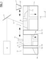
- Fig.1 shows a schematic of a system which is designed for the production of soft magnetic molded parts and which is constructed similarly to a system for selective laser sintering.
- the X and Z axes are shown, which define the cutting plane in which the system is shown.
- the Y axis extends perpendicular to these two axes X and Z.
- the system comprises a reservoir 10 for receiving and supplying the starting material 21, 22, a production bed 11 in which the molded part 20 is manufactured, a coater 12 for forming a layer of the starting material 21, 22 in the production bed 11, a laser 13 and a scanning device 14.
- the reservoir 10 has a bottom 10a which can be lifted in the Z direction and which is, for example, part of a displaceable piston.
- the production bed 11 has a work platform 11a that can be lowered in the Z direction and is, for example, part of a movable piston.
- the coater 12 is movable along the production bed 11, ie in the X-direction, and is designed, for example, as a rotatable roller or doctor blade.
- the laser 13 and the scanning device 14 are designed to generate a laser beam 15, which serves for the local and temporally concentrated heating of a layer of the starting material in the production bed 11.
- the laser 13 generates a beam that is typically in the infrared range.
- a CO 2 laser or an Nd:YAG laser, for example, are suitable lasers.
- the scanning device 14 comprises optical elements, for example one or more lenses and one or more mirrors, and serves to optionally focus or expand the beam generated by the laser 13 and to guide it along a predetermined path in the production bed 11, which defines the shape of the molded part 20 at the level at which the layer is heated.
- a further reservoir 16 serves as a silo from which starting material 21, 22 can be transferred to the reservoir 10 and/or unused starting material 21, 22 can be taken up from the production bed 11.
- the reservoir 10, the production bed 11 and the reservoir 16 are limited by walls 10b, 10c, 11b, 11c, 16a, 16b. These are bordered at the front and rear, ie in the Y-direction, by further (in the Fig.1 not visible) walls and/or are rounded so that a laterally closed chamber is created.
- a possible method for producing a soft magnetic molded part 20 is as follows: Geometric data are provided which define the desired geometry of the molded part to be manufactured. This geometric data is available, for example, as CAD data and defines the path along which the laser beam 15 is to be guided in a respective layer.
- the starting material 21, 22 is provided in the reservoir 10.
- a mixture of magnetically conductive particles 21 and an additive 22 is used as the starting material to form electrical insulation points 22. These serve in the finished molded part 20 to interrupt or at least reduce eddy currents that arise during magnetization.
- the mixture is present, for example, in a pourable form, with the additive 22 preferably being present as particles. It is also conceivable to provide the additive 22 in pasty, liquid or gaseous form so that it is at least in contact with the layer that consists of the magnetically conductive particles 21 in the production bed 11 and which is heated with the laser beam 15.
- the magnetically conductive particles 21 are free from complete envelopment by an electrical insulating layer.
- the additive 22 can be present as particles whose grain size is smaller than that of the magnetically conductive particles 21.
- the median value (d 50 ) of the grain size distribution of the additive 22 is then smaller than the median value (d 50 ) of the grain size distribution of the magnetically conductive particles 21. It is also conceivable that the additive 22 is present as particles with a grain size that is at least as large as that of the magnetically conductive particles 21.
- the floor 10a is lifted and a layer is formed on the working platform 11a by means of the coater 12.
- the layer is full-surface and extends according to Fig.1 in the XY plane. It typically has a thickness in the range of 1 to 200 micrometers.
- the laser beam 15 is guided along the desired path.
- the starting material 21, 22 is heated at the corresponding points so that the magnetically conductive particles 21 bond with each other.
- the magnetically conductive particles 21 are melted and the additive 22 forms electrical insulation points in the spaces between the magnetically conductive particles 21.
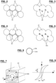
- FIG. 2 and 3 and 4 and 5 show a layer with magnetically conductive particles 21 and additive 22 before and after heating, respectively.
- the magnetically conductive particles 21 have bonded in the contact area; however, their structure remains essentially intact.
- the energy of the laser 13 can be introduced very quickly, so that the additive 22 is enclosed in the gaps.
- Fig.3 the situation is shown in which the additive 22 has a higher melting temperature than the magnetically conductive particles 21, so that it is not melted by the laser beam 22.
- Fig.5 the situation is shown in which the additive 22 has the same or a lower melting temperature than the magnetically conductive particles 21, so that it is melted by the laser beam 22 and forms an insulating layer 22a in the respective space between the magnetically conductive particles 21.
- additive 22 for example as a gas
- this can lead to a change in the surface of the magnetically conductive particles 21 when heated, so that an oxide layer is formed in the gaps, which act as electrical insulation points.
- the production bed 11 is located in a closed chamber, to which the additive 22 is supplied as a gas.
- the additive 22 is initially in solid form (e.g. as Acrawax) and melts when heated, so that a gas is formed that causes the formation of an oxide layer in the respective gap.
- the work platform 11a After heating, the work platform 11a is lowered by one layer thickness.
- the base 10a is raised and a next layer of starting material 21, 22 is applied to the production bed 11 by means of the coater 12. Heating is then carried out again by means of the laser beam 15 at the specified locations.
- the finished molded part 20 is created by successively applying a layer and heating it.
- the molded part 20 is embedded in the production bed 11 in the rest of the starting material 21, 22, which has not been heated by means of the laser beam 15. At the end of production, the molded part 20 is removed from the production bed 11 and any remaining starting material 21, 22 is knocked off, brushed off and/or removed in another way.
- each layer has a substantially homogeneous concentration of starting material 21, 22.
- the molded part 20 therefore has a substantially homogeneous distribution of the electrical insulation points.
- a molded part 20 can be produced which has a locally different distribution of insulation points.
- the system according to Fig.1 an application device in the form of a movable working head 17 is provided, by means of which a further additive 22' can be applied to a layer formed by the coater 12 at predetermined locations before it is heated by means of the laser beam 15.
- the working head 17 is designed, for example, as a spray or print head, by means of which the further additive 22' can be applied, for example in solid or liquid form, at predetermined locations.
- the further additive 22' in the working head 17 can, for example, correspond to the additive 22 or be another suitable material which, after heating, forms electrically insulating points in the molded part 20.
- a production head for applying the magnetically conductive particles 21 has a fixing unit with a laser, by means of which energy can be transferred to the magnetically conductive particles 21 in a time-concentrated manner in order to cause melting.
- adiabatic pressing In addition to additive manufacturing processes, it is also conceivable to produce a molded part 20 in one piece by means of so-called adiabatic forming or compaction ("adiabatic pressing").
- a blank is produced from the mixture of magnetically conductive particles 21 and additive 22, e.g. by pressing, which blank corresponds to the desired shape of the molded part 20.
- the blank is not yet solidified, so that the particles may only hold together minimally.
- An additional binding agent can be provided and/or the additive 22 itself acts as such a binding agent, e.g. in the case of silicone.
- the blank is then compacted so that it has the desired hardness.
- energy of over 5000 joules per mm 3 and preferably over 6000 joules per mm 3 is introduced by means of at least one impact, which causes the particles 21 to fuse together.
- the impact is carried out, for example, by means of high-speed pressing, as is the case, for example, in the WO 2016/135187 A1 is described, according to which a ram acts on the blank, which for example with more than 5 m/s.
- this known process provides for sintering by heating in an oven after compaction. Such subsequent sintering is not provided here for fusing the powder grains.
- the inventor has determined that the particles 21 may not be fused together enough by the adiabatic pressing and/or undesirable air inclusions may occur if there is too much empty space between the material to be compacted beforehand.
- a process step is therefore preferably provided before the adiabatic pressing in which the empty space is reduced.
- the empty space reduction is carried out without heat input and is carried out, for example, by the action of a stamp, vibration, suction of air, application of a vacuum and/or by other suitable measures.
- the step of reducing the empty space and the step of adiabatic pressing are carried out on the same machine.
- the machine has a negative mold that defines the shape of the molded part and is open at the top.
- the negative mold is filled with the magnetically conductive particles and optionally also with the additive if this is in solid or liquid form, for example.
- the empty space between the particles is reduced as mentioned above.
- the punch is used for this purpose, which is later used as a ram for the adiabatic pressing, although it is moved much more slowly and with a smaller stroke. The adiabatic pressing then takes place.
- the punch for adiabatic pressing in several parts. This allows the parts of the punch to be moved with different strokes and thus compensate for density differences in the molded part.
- Adiabatic pressing as a manufacturing process has the advantage over manufacturing using an additive process that a molded part can be produced in a shorter time and is therefore particularly suitable for economical production in large quantities.
- stator parts can be manufactured that are designed for a magnetic flux that should not only occur in one plane during operation, but in all three directions.
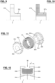
- Figs. 9 and 10 show one half of a stator part made of a flux tube 20a or 20'a and a toothed disk 20b or 20'b in a longitudinal section, where A denotes the longitudinal axis.
- the stator part 20a, 20b according to Fig.9 can be manufactured integrally using one of the manufacturing processes described here and allows the desired flux conduction to be achieved by appropriate design of the geometry.
- the magnetic flux can be redirected in such a way that it is first aligned transversely to the axis A and then in this direction A.
- the Fig.10 The stator part 20'a, 20'b shown is manufactured using the previously known manufacturing process in which the flux tube 20'a has a layered structure and the disk part 20'b consists of a laminated core. The magnetic flux in the flux tube 20'a and in the disk part 20'b occurs essentially in one direction.
- Fig. 11 shows in a perspective exploded view an arrangement with two toothed disks 20b, each with an integrally attached part of the flux tube 20a.
- This is divided in such a way that after the coil 30 has been attached, it can be put together in a defined position in which the teeth of the two disks 20b are aligned with each other as desired. In the example, this is achieved, as with a claw coupling, by claws 20c that engage in recesses 20d on the opposite part.
- a slot 20e is also visible in the respective stator part 20a, 20b, which prevents a ring closure during operation.
- the slot 20e can either be provided during integral production or it can be added later, e.g. by milling, since the molded part allows this due to its hardness.
- Fig. 12 shows in longitudinal section one half of the coil 30 and two toothed disks 20b each with the integrally attached part of the flux tube 20a, where A is the rotor or stator axis.
- A is the rotor or stator axis.
- a tooth 20f of the stator part 20a, 20b is shaped so that it projects inwards (cf. length L in Fig. 12 ) and thus compared to the variant according to Fig.10 longer in the direction of axis A.
- Stator parts can also be manufactured which are provided with an inner cavity and/or integrally manufactured additional elements.
- An example of such a stator part is shown in Fig. 13
- the inner cavity 26 forms an inner channel through which air can be transported to cool the coil 30 mounted on the winding body 31.
- the inner cavity 27 also forms an inner channel, but is provided with a pipe 28 to pass water through for cooling, for example. Cooling fins 29 are also indicated in this figure.
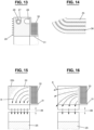
- Fig. 14 shows an example which has layers of a soft magnetic material 35 and of insulating material 36.
- the layers 35 are formed, for example, from the starting material 21, 22, which in the system according to Fig.1 is used.
- the insulation layers 36 are, for example, Fig.1
- a type of "3D sheet metal structure" can thus be formed, which can expand not only in the plane but in all three directions as required, for example as shown in the Fig. 14 indicated on the left.
- Fig. 15 shows an example in which the distribution of the electrical insulation points 22b is inhomogeneous.
- insulation points 22b are concentrated on the side of the stator pole 24 opposite the coil 30. This better redirects the magnetic flux B so that it reaches the rotor pole 25 to a greater extent via the air gap 38. Without this concentration of insulation points 22b, part of the magnetic field exits the stator pole at the side as shown in Fig. 16 is indicated. Accordingly, unusable flow losses result here.
Landscapes
- Engineering & Computer Science (AREA)
- Power Engineering (AREA)
- Chemical & Material Sciences (AREA)
- Manufacturing & Machinery (AREA)
- Materials Engineering (AREA)
- Dispersion Chemistry (AREA)
- Mechanical Engineering (AREA)
- Powder Metallurgy (AREA)
- Manufacture Of Motors, Generators (AREA)
- Soft Magnetic Materials (AREA)
Applications Claiming Priority (3)
| Application Number | Priority Date | Filing Date | Title |
|---|---|---|---|
| EP17209979 | 2017-12-22 | ||
| EP18826705.8A EP3729476B1 (fr) | 2017-12-22 | 2018-12-21 | Procédé de fabrication d'une pièce formée magnétique douce et pièce formée magnétique douce |
| PCT/EP2018/086520 WO2019122307A1 (fr) | 2017-12-22 | 2018-12-21 | Procédé de fabrication d'une pièce moulée à aimantation temporaire et pièce moulée à aimantation temporaire |
Related Parent Applications (1)
| Application Number | Title | Priority Date | Filing Date |
|---|---|---|---|
| EP18826705.8A Division EP3729476B1 (fr) | 2017-12-22 | 2018-12-21 | Procédé de fabrication d'une pièce formée magnétique douce et pièce formée magnétique douce |
Publications (2)
| Publication Number | Publication Date |
|---|---|
| EP4417346A2 true EP4417346A2 (fr) | 2024-08-21 |
| EP4417346A3 EP4417346A3 (fr) | 2025-04-23 |
Family
ID=60990569
Family Applications (2)
| Application Number | Title | Priority Date | Filing Date |
|---|---|---|---|
| EP24180677.7A Pending EP4417346A3 (fr) | 2017-12-22 | 2018-12-21 | Procédé de fabrication d'un élément moulé magnétique doux et élément moulé magnétique doux |
| EP18826705.8A Active EP3729476B1 (fr) | 2017-12-22 | 2018-12-21 | Procédé de fabrication d'une pièce formée magnétique douce et pièce formée magnétique douce |
Family Applications After (1)
| Application Number | Title | Priority Date | Filing Date |
|---|---|---|---|
| EP18826705.8A Active EP3729476B1 (fr) | 2017-12-22 | 2018-12-21 | Procédé de fabrication d'une pièce formée magnétique douce et pièce formée magnétique douce |
Country Status (5)
| Country | Link |
|---|---|
| US (1) | US20210065942A1 (fr) |
| EP (2) | EP4417346A3 (fr) |
| JP (1) | JP2021508005A (fr) |
| CN (1) | CN111602212A (fr) |
| WO (1) | WO2019122307A1 (fr) |
Families Citing this family (2)
| Publication number | Priority date | Publication date | Assignee | Title |
|---|---|---|---|---|
| JP7367358B2 (ja) * | 2019-07-11 | 2023-10-24 | 大同特殊鋼株式会社 | ボンド磁石製造方法 |
| WO2025024532A1 (fr) * | 2023-07-24 | 2025-01-30 | University Of Pittsburgh-Of The Commonwealth System Of Higher Education | Composants passifs fabriqués de manière additive pour applications à haute fréquence |
Citations (3)
| Publication number | Priority date | Publication date | Assignee | Title |
|---|---|---|---|---|
| DE102013021944A1 (de) | 2013-12-20 | 2015-06-25 | Dominique Paetz | Generative Fertigungseinrichtung |
| DE102014006519A1 (de) | 2014-05-03 | 2015-11-05 | Smart Material Printing B.V. | Verwendung magnetischer und/oder magnetisierbarer, polymerer Mikro- und/oder Nanocomposite zur Herstellung komplexer, magnetischer und/oder magnetisierbarer Formteile mithilfe additiver Fabrikatoren |
| WO2016135187A1 (fr) | 2015-02-25 | 2016-09-01 | Hyp Uthyrning Ab | Compactage de poudre métallique dispersée par jet de gaz sur une pièce |
Family Cites Families (18)
| Publication number | Priority date | Publication date | Assignee | Title |
|---|---|---|---|---|
| ATE197131T1 (de) * | 1995-06-21 | 2000-11-15 | Hydropulsor Ab | Schlagschneidvorrichtung |
| US6413339B1 (en) * | 1999-12-22 | 2002-07-02 | International Business Machines Corporation | Low temperature sintering of ferrite materials |
| SE0102103D0 (sv) * | 2001-06-13 | 2001-06-13 | Hoeganaes Ab | High density soft magnetic products and method for the preparation thereof |
| US7634642B2 (en) * | 2006-07-06 | 2009-12-15 | International Business Machines Corporation | Mechanism to save and restore cache and translation trace for fast context switch |
| JP4721456B2 (ja) * | 2007-03-19 | 2011-07-13 | 日立粉末冶金株式会社 | 圧粉磁心の製造方法 |
| US20100092328A1 (en) * | 2008-10-09 | 2010-04-15 | Glenn Thomas | High velocity adiabatic impact powder compaction |
| WO2012015243A2 (fr) * | 2010-07-30 | 2012-02-02 | Lg Innotek Co., Ltd. | Appareil de frittage par presse à chaud et élément presse |
| DE102012210081A1 (de) * | 2012-06-15 | 2013-12-19 | Siemens Ag | Verfahren zur Herstellung eines Permanentmagneten |
| US9512544B2 (en) * | 2013-07-11 | 2016-12-06 | Tundra Composites, LLC | Surface modified particulate and sintered or injection molded products |
| JP2015133416A (ja) * | 2014-01-14 | 2015-07-23 | 大同特殊鋼株式会社 | 電磁波吸収体及びその製造方法 |
| KR101947118B1 (ko) * | 2014-07-16 | 2019-02-12 | 히타치 긴조쿠 가부시키가이샤 | 자심의 제조 방법, 자심 및 이를 이용한 코일 부품 |
| CN106796835B (zh) * | 2014-08-12 | 2019-05-21 | Abb瑞士股份有限公司 | 具有不同磁性质的区域的磁体以及用于形成这种磁体的方法 |
| DE102015105431A1 (de) * | 2015-04-09 | 2016-10-13 | Volkswagen Ag | Verfahren zur Herstellung eines weichmagnetischen Körpers |
| TWI576872B (zh) * | 2015-12-17 | 2017-04-01 | 財團法人工業技術研究院 | 磁性元件的製造方法 |
| WO2018017072A1 (fr) * | 2016-07-20 | 2018-01-25 | Hewlett-Packard Development Company, L.P. | Ensembles de matériaux |
| US10254499B1 (en) * | 2016-08-05 | 2019-04-09 | Southern Methodist University | Additive manufacturing of active devices using dielectric, conductive and magnetic materials |
| WO2019059256A1 (fr) * | 2017-09-25 | 2019-03-28 | 国立研究開発法人産業技術総合研究所 | Matériau magnétique et son procédé de production |
| US10682551B2 (en) * | 2017-12-01 | 2020-06-16 | Acushnet Company | Golf balls with aerodynamic subsurfaces |
-
2018
- 2018-12-21 EP EP24180677.7A patent/EP4417346A3/fr active Pending
- 2018-12-21 CN CN201880082972.6A patent/CN111602212A/zh active Pending
- 2018-12-21 US US16/956,770 patent/US20210065942A1/en not_active Abandoned
- 2018-12-21 JP JP2020554929A patent/JP2021508005A/ja active Pending
- 2018-12-21 WO PCT/EP2018/086520 patent/WO2019122307A1/fr not_active Ceased
- 2018-12-21 EP EP18826705.8A patent/EP3729476B1/fr active Active
Patent Citations (3)
| Publication number | Priority date | Publication date | Assignee | Title |
|---|---|---|---|---|
| DE102013021944A1 (de) | 2013-12-20 | 2015-06-25 | Dominique Paetz | Generative Fertigungseinrichtung |
| DE102014006519A1 (de) | 2014-05-03 | 2015-11-05 | Smart Material Printing B.V. | Verwendung magnetischer und/oder magnetisierbarer, polymerer Mikro- und/oder Nanocomposite zur Herstellung komplexer, magnetischer und/oder magnetisierbarer Formteile mithilfe additiver Fabrikatoren |
| WO2016135187A1 (fr) | 2015-02-25 | 2016-09-01 | Hyp Uthyrning Ab | Compactage de poudre métallique dispersée par jet de gaz sur une pièce |
Also Published As
| Publication number | Publication date |
|---|---|
| WO2019122307A1 (fr) | 2019-06-27 |
| EP3729476C0 (fr) | 2024-06-12 |
| EP3729476A1 (fr) | 2020-10-28 |
| EP3729476B1 (fr) | 2024-06-12 |
| JP2021508005A (ja) | 2021-02-25 |
| EP4417346A3 (fr) | 2025-04-23 |
| CN111602212A (zh) | 2020-08-28 |
| US20210065942A1 (en) | 2021-03-04 |
Similar Documents
| Publication | Publication Date | Title |
|---|---|---|
| DE3839545C2 (de) | Verfahren und Vorrichtung zur Herstellung eines anisotropen Magneten | |
| DE10114939B4 (de) | Pulverpressvorrichtung und Verfahren zur Herstellung eines magnetischen Seltenerdmetall-Legierungspulverpresslings | |
| DE112007003090T5 (de) | Verfahren zum Herstellen eines dreidimensional geformten Gegenstandes | |
| DE102019113879B4 (de) | Verfahren zum Bilden eines Magneten und Magnet | |
| DE102013212826A1 (de) | Endloses Transportband und Verfahren zur Herstellung eines endlosen Transportbands | |
| DE102016119654B4 (de) | Verfahren zur Herstellung eines weichmagnetischen Kernmaterials und weichmagnetisches Kernmaterial | |
| DE112019006615T5 (de) | Additive Herstellung von Magnet Arrays | |
| DE10050703A1 (de) | Verfahren zur Formung von rotierbaren Elektromagneten mit Weich- und Hartmagnetkomponenten | |
| EP3053675A1 (fr) | Unite d'application de poudre, dispositif correspondant et procédé d'utilisation d'une unité d'application de poudre | |
| EP3729476B1 (fr) | Procédé de fabrication d'une pièce formée magnétique douce et pièce formée magnétique douce | |
| EP3250004A1 (fr) | Dispositif de chauffage inductif d'un composant | |
| DE102011113308A1 (de) | Bolzenschweißverfahren und -vorrichtung | |
| DE102015113976A1 (de) | Verfahren zur Herstellung eines seltene-Erden-Magneten | |
| DE2850783A1 (de) | Verfahren zur einstellung der dicke einer fluessigen metallbeschichtung auf einem metallsubstrat sowie vorrichtung zur durchfuehrung eines solchen verfahrens | |
| DE102009051975A1 (de) | Lineardirektantrieb | |
| DE102013226257A1 (de) | Verfahren zur Herstellung von Kontaktmaterialstücken für Vakuumschaltröhren | |
| EP2626988A2 (fr) | Procédé de fabrication d'un rotor et rotor | |
| AT521006B1 (de) | Verfahren zum Herstellen eines Bauteils mit weichmagnetischen Eigenschaften | |
| EP1111631A2 (fr) | Procédé pour la production d'une ébauche d'un élément de contact et d'un élément de contact, ébauche d'un élément de contact, élément de contact et ensemble d'élément de contact pour l'utilisation dans un champs magnétique axial d'une chambre sous vide | |
| DE102015206326A1 (de) | Weichmagnetischer Verbundwerkstoff und entsprechende Verfahren zum Herstellen eines weichmagnetischen Verbundwerkstoffs | |
| DE102017207940A1 (de) | Rotor und elektrische Maschine | |
| DE2850050C2 (de) | Verfahren zur Herstellung einer elektromagnetischen Aufspannplatte | |
| WO2019137976A1 (fr) | Procédé et appareil de fabrication d'objets en métal | |
| AT504925B1 (de) | Punktschweisselektrode und punktschweissverfahren | |
| DE69033992T2 (de) | Matrize zum Strangpressen |
Legal Events
| Date | Code | Title | Description |
|---|---|---|---|
| PUAI | Public reference made under article 153(3) epc to a published international application that has entered the european phase |
Free format text: ORIGINAL CODE: 0009012 |
|
| STAA | Information on the status of an ep patent application or granted ep patent |
Free format text: STATUS: THE APPLICATION HAS BEEN PUBLISHED |
|
| AC | Divisional application: reference to earlier application |
Ref document number: 3729476 Country of ref document: EP Kind code of ref document: P |
|
| AK | Designated contracting states |
Kind code of ref document: A2 Designated state(s): AL AT BE BG CH CY CZ DE DK EE ES FI FR GB GR HR HU IE IS IT LI LT LU LV MC MK MT NL NO PL PT RO RS SE SI SK SM TR |
|
| REG | Reference to a national code |
Ref country code: DE Ref legal event code: R079 Free format text: PREVIOUS MAIN CLASS: B22F0010200000 Ipc: H01F0001220000 |
|
| RIC1 | Information provided on ipc code assigned before grant |
Ipc: B22F 12/63 20210101ALN20241105BHEP Ipc: B22F 12/49 20210101ALN20241105BHEP Ipc: B22F 10/28 20210101ALN20241105BHEP Ipc: B33Y 80/00 20150101ALI20241105BHEP Ipc: B33Y 10/00 20150101ALI20241105BHEP Ipc: B22F 12/10 20210101ALI20241105BHEP Ipc: B22F 3/087 20060101ALI20241105BHEP Ipc: B22F 3/105 20060101ALI20241105BHEP Ipc: H01F 3/08 20060101ALI20241105BHEP Ipc: H01F 41/02 20060101ALI20241105BHEP Ipc: H01F 41/16 20060101ALI20241105BHEP Ipc: H01F 1/22 20060101AFI20241105BHEP |
|
| PUAL | Search report despatched |
Free format text: ORIGINAL CODE: 0009013 |
|
| AK | Designated contracting states |
Kind code of ref document: A3 Designated state(s): AL AT BE BG CH CY CZ DE DK EE ES FI FR GB GR HR HU IE IS IT LI LT LU LV MC MK MT NL NO PL PT RO RS SE SI SK SM TR |
|
| RIC1 | Information provided on ipc code assigned before grant |
Ipc: B22F 12/63 20210101ALN20250319BHEP Ipc: B22F 12/49 20210101ALN20250319BHEP Ipc: B22F 10/28 20210101ALN20250319BHEP Ipc: B33Y 80/00 20150101ALI20250319BHEP Ipc: B33Y 10/00 20150101ALI20250319BHEP Ipc: B22F 12/10 20210101ALI20250319BHEP Ipc: B22F 3/087 20060101ALI20250319BHEP Ipc: B22F 3/105 20060101ALI20250319BHEP Ipc: H01F 3/08 20060101ALI20250319BHEP Ipc: H01F 41/02 20060101ALI20250319BHEP Ipc: H01F 41/16 20060101ALI20250319BHEP Ipc: H01F 1/22 20060101AFI20250319BHEP |
|
| STAA | Information on the status of an ep patent application or granted ep patent |
Free format text: STATUS: REQUEST FOR EXAMINATION WAS MADE |
|
| 17P | Request for examination filed |
Effective date: 20251023 |