EP4418507A2 - Procédé de fabrication d'un paquet de tôles, paquet de tôles et machine électrique - Google Patents
Procédé de fabrication d'un paquet de tôles, paquet de tôles et machine électrique Download PDFInfo
- Publication number
- EP4418507A2 EP4418507A2 EP24180243.8A EP24180243A EP4418507A2 EP 4418507 A2 EP4418507 A2 EP 4418507A2 EP 24180243 A EP24180243 A EP 24180243A EP 4418507 A2 EP4418507 A2 EP 4418507A2
- Authority
- EP
- European Patent Office
- Prior art keywords
- adhesive coating
- molded part
- adhesive
- stack
- sheet
- Prior art date
- Legal status (The legal status is an assumption and is not a legal conclusion. Google has not performed a legal analysis and makes no representation as to the accuracy of the status listed.)
- Pending
Links
- 238000004519 manufacturing process Methods 0.000 title claims abstract description 19
- 230000001070 adhesive effect Effects 0.000 claims abstract description 179
- 239000000853 adhesive Substances 0.000 claims abstract description 178
- 238000000576 coating method Methods 0.000 claims abstract description 124
- 239000011248 coating agent Substances 0.000 claims abstract description 121
- 238000000034 method Methods 0.000 claims abstract description 69
- 238000005520 cutting process Methods 0.000 claims abstract description 43
- 230000003213 activating effect Effects 0.000 claims abstract description 34
- 239000012530 fluid Substances 0.000 claims abstract description 33
- 239000002184 metal Substances 0.000 claims description 40
- 229910052751 metal Inorganic materials 0.000 claims description 40
- 241000446313 Lamella Species 0.000 claims description 33
- 230000004913 activation Effects 0.000 claims description 27
- 150000003672 ureas Chemical class 0.000 claims description 26
- 239000003822 epoxy resin Substances 0.000 claims description 21
- 229920000647 polyepoxide Polymers 0.000 claims description 21
- 238000004080 punching Methods 0.000 claims description 21
- 239000003795 chemical substances by application Substances 0.000 claims description 19
- 239000000203 mixture Substances 0.000 claims description 17
- PUNIDMUCDALJAS-UHFFFAOYSA-N C(C1=CC=C(C=C1)N(C(=O)NC)C)C1=CC=C(C=C1)N(C(=O)NC)C Chemical compound C(C1=CC=C(C=C1)N(C(=O)NC)C)C1=CC=C(C=C1)N(C(=O)NC)C PUNIDMUCDALJAS-UHFFFAOYSA-N 0.000 claims description 13
- XSQUKJJJFZCRTK-UHFFFAOYSA-N Urea Natural products NC(N)=O XSQUKJJJFZCRTK-UHFFFAOYSA-N 0.000 claims description 12
- 125000002496 methyl group Chemical group [H]C([H])([H])* 0.000 claims description 12
- 230000005855 radiation Effects 0.000 claims description 12
- 239000000126 substance Substances 0.000 claims description 11
- YNAVUWVOSKDBBP-UHFFFAOYSA-N Morpholine Chemical compound C1COCCN1 YNAVUWVOSKDBBP-UHFFFAOYSA-N 0.000 claims description 10
- 229910052736 halogen Inorganic materials 0.000 claims description 10
- 150000002367 halogens Chemical class 0.000 claims description 10
- 125000000217 alkyl group Chemical group 0.000 claims description 9
- 239000004849 latent hardener Substances 0.000 claims description 9
- 239000006185 dispersion Substances 0.000 claims description 8
- 125000003118 aryl group Chemical group 0.000 claims description 7
- 238000010382 chemical cross-linking Methods 0.000 claims description 7
- 125000000524 functional group Chemical group 0.000 claims description 7
- 239000007787 solid Substances 0.000 claims description 7
- UFHFLCQGNIYNRP-UHFFFAOYSA-N Hydrogen Chemical compound [H][H] UFHFLCQGNIYNRP-UHFFFAOYSA-N 0.000 claims description 6
- 125000003545 alkoxy group Chemical group 0.000 claims description 6
- 125000000484 butyl group Chemical group [H]C([*])([H])C([H])([H])C([H])([H])C([H])([H])[H] 0.000 claims description 6
- 125000001495 ethyl group Chemical group [H]C([H])([H])C([H])([H])* 0.000 claims description 6
- 229910052739 hydrogen Inorganic materials 0.000 claims description 6
- 239000001257 hydrogen Substances 0.000 claims description 6
- 125000001436 propyl group Chemical group [H]C([*])([H])C([H])([H])C([H])([H])[H] 0.000 claims description 6
- 230000009467 reduction Effects 0.000 claims description 6
- ZGUAANUOYYFJEK-UHFFFAOYSA-N 1,1-dimethyl-3-(4-methyl-3-nitrophenyl)urea Chemical compound CN(C)C(=O)NC1=CC=C(C)C([N+]([O-])=O)=C1 ZGUAANUOYYFJEK-UHFFFAOYSA-N 0.000 claims description 5
- XMTQQYYKAHVGBJ-UHFFFAOYSA-N 3-(3,4-DICHLOROPHENYL)-1,1-DIMETHYLUREA Chemical compound CN(C)C(=O)NC1=CC=C(Cl)C(Cl)=C1 XMTQQYYKAHVGBJ-UHFFFAOYSA-N 0.000 claims description 5
- WWXUVGVLWPMBEY-UHFFFAOYSA-N 3-(3-chloro-4-ethylphenyl)-1,1-dimethylurea Chemical compound CCC1=CC=C(NC(=O)N(C)C)C=C1Cl WWXUVGVLWPMBEY-UHFFFAOYSA-N 0.000 claims description 5
- IOSRDCDJNGRQKT-UHFFFAOYSA-N 3-(3-chloro-4-methylphenyl)-1,1-dimethylthiourea Chemical compound CN(C)C(=S)NC1=CC=C(C)C(Cl)=C1 IOSRDCDJNGRQKT-UHFFFAOYSA-N 0.000 claims description 5
- 125000002887 hydroxy group Chemical group [H]O* 0.000 claims description 5
- 230000001976 improved effect Effects 0.000 claims description 5
- 230000006698 induction Effects 0.000 claims description 5
- 239000007788 liquid Substances 0.000 claims description 5
- DSRNRYQBBJQVCW-UHFFFAOYSA-N metoxuron Chemical compound COC1=CC=C(NC(=O)N(C)C)C=C1Cl DSRNRYQBBJQVCW-UHFFFAOYSA-N 0.000 claims description 5
- 229920000642 polymer Polymers 0.000 claims description 5
- 238000000926 separation method Methods 0.000 claims description 5
- YBBLOADPFWKNGS-UHFFFAOYSA-N 1,1-dimethylurea Chemical compound CN(C)C(N)=O YBBLOADPFWKNGS-UHFFFAOYSA-N 0.000 claims description 4
- 239000012809 cooling fluid Substances 0.000 claims description 4
- 229920005989 resin Polymers 0.000 claims description 4
- 239000011347 resin Substances 0.000 claims description 4
- MGJKQDOBUOMPEZ-UHFFFAOYSA-N N,N'-dimethylurea Chemical compound CNC(=O)NC MGJKQDOBUOMPEZ-UHFFFAOYSA-N 0.000 claims description 3
- 125000003342 alkenyl group Chemical group 0.000 claims description 3
- 125000003710 aryl alkyl group Chemical group 0.000 claims description 3
- 125000004104 aryloxy group Chemical group 0.000 claims description 3
- 230000001588 bifunctional effect Effects 0.000 claims description 3
- 239000004202 carbamide Substances 0.000 claims description 3
- JXCGFZXSOMJFOA-UHFFFAOYSA-N chlorotoluron Chemical compound CN(C)C(=O)NC1=CC=C(C)C(Cl)=C1 JXCGFZXSOMJFOA-UHFFFAOYSA-N 0.000 claims description 3
- 239000000110 cooling liquid Substances 0.000 claims description 3
- 125000004093 cyano group Chemical group *C#N 0.000 claims description 3
- 125000000392 cycloalkenyl group Chemical group 0.000 claims description 3
- 125000000753 cycloalkyl group Chemical group 0.000 claims description 3
- 125000000623 heterocyclic group Chemical group 0.000 claims description 3
- 150000002431 hydrogen Chemical class 0.000 claims description 3
- 125000000449 nitro group Chemical group [O-][N+](*)=O 0.000 claims description 3
- 229910052760 oxygen Inorganic materials 0.000 claims description 3
- 229910052717 sulfur Inorganic materials 0.000 claims description 3
- 238000005056 compaction Methods 0.000 abstract description 19
- 239000000523 sample Substances 0.000 description 31
- 230000008901 benefit Effects 0.000 description 22
- 230000008569 process Effects 0.000 description 20
- 238000012360 testing method Methods 0.000 description 18
- 238000011161 development Methods 0.000 description 16
- 230000018109 developmental process Effects 0.000 description 16
- 239000002966 varnish Substances 0.000 description 14
- 238000010438 heat treatment Methods 0.000 description 13
- 238000003475 lamination Methods 0.000 description 13
- 230000000694 effects Effects 0.000 description 10
- 238000006243 chemical reaction Methods 0.000 description 8
- 230000001965 increasing effect Effects 0.000 description 8
- 239000000654 additive Substances 0.000 description 7
- LNEPOXFFQSENCJ-UHFFFAOYSA-N haloperidol Chemical compound C1CC(O)(C=2C=CC(Cl)=CC=2)CCN1CCCC(=O)C1=CC=C(F)C=C1 LNEPOXFFQSENCJ-UHFFFAOYSA-N 0.000 description 7
- 238000003860 storage Methods 0.000 description 7
- -1 barium Chemical compound 0.000 description 6
- RAXXELZNTBOGNW-UHFFFAOYSA-N imidazole Natural products C1=CNC=N1 RAXXELZNTBOGNW-UHFFFAOYSA-N 0.000 description 6
- 239000010410 layer Substances 0.000 description 5
- 239000000463 material Substances 0.000 description 5
- 229910000976 Electrical steel Inorganic materials 0.000 description 4
- XEEYBQQBJWHFJM-UHFFFAOYSA-N Iron Chemical compound [Fe] XEEYBQQBJWHFJM-UHFFFAOYSA-N 0.000 description 4
- 238000001816 cooling Methods 0.000 description 4
- 239000012535 impurity Substances 0.000 description 4
- 238000009413 insulation Methods 0.000 description 4
- 239000002346 layers by function Substances 0.000 description 4
- 229910001224 Grain-oriented electrical steel Inorganic materials 0.000 description 3
- 239000012790 adhesive layer Substances 0.000 description 3
- 230000015572 biosynthetic process Effects 0.000 description 3
- 238000007906 compression Methods 0.000 description 3
- 230000001627 detrimental effect Effects 0.000 description 3
- 239000000975 dye Substances 0.000 description 3
- 125000001997 phenyl group Chemical group [H]C1=C([H])C([H])=C(*)C([H])=C1[H] 0.000 description 3
- 239000004848 polyfunctional curative Substances 0.000 description 3
- 230000035882 stress Effects 0.000 description 3
- SQZCAOHYQSOZCE-UHFFFAOYSA-N 1-(diaminomethylidene)-2-(2-methylphenyl)guanidine Chemical compound CC1=CC=CC=C1N=C(N)N=C(N)N SQZCAOHYQSOZCE-UHFFFAOYSA-N 0.000 description 2
- ZCUJYXPAKHMBAZ-UHFFFAOYSA-N 2-phenyl-1h-imidazole Chemical compound C1=CNC(C=2C=CC=CC=2)=N1 ZCUJYXPAKHMBAZ-UHFFFAOYSA-N 0.000 description 2
- IJGRMHOSHXDMSA-UHFFFAOYSA-N Atomic nitrogen Chemical compound N#N IJGRMHOSHXDMSA-UHFFFAOYSA-N 0.000 description 2
- ISWSIDIOOBJBQZ-UHFFFAOYSA-N Phenol Chemical compound OC1=CC=CC=C1 ISWSIDIOOBJBQZ-UHFFFAOYSA-N 0.000 description 2
- 239000004844 aliphatic epoxy resin Substances 0.000 description 2
- 125000001931 aliphatic group Chemical group 0.000 description 2
- 229910045601 alloy Inorganic materials 0.000 description 2
- 239000000956 alloy Substances 0.000 description 2
- 239000004841 bisphenol A epoxy resin Substances 0.000 description 2
- 239000002131 composite material Substances 0.000 description 2
- 150000001875 compounds Chemical class 0.000 description 2
- 230000006835 compression Effects 0.000 description 2
- 238000013461 design Methods 0.000 description 2
- ZUOUZKKEUPVFJK-UHFFFAOYSA-N diphenyl Chemical compound C1=CC=CC=C1C1=CC=CC=C1 ZUOUZKKEUPVFJK-UHFFFAOYSA-N 0.000 description 2
- 230000001939 inductive effect Effects 0.000 description 2
- 239000004922 lacquer Substances 0.000 description 2
- 230000007774 longterm Effects 0.000 description 2
- 239000004843 novolac epoxy resin Substances 0.000 description 2
- 239000003960 organic solvent Substances 0.000 description 2
- 238000004806 packaging method and process Methods 0.000 description 2
- 235000011837 pasties Nutrition 0.000 description 2
- 239000000843 powder Substances 0.000 description 2
- 238000003825 pressing Methods 0.000 description 2
- 238000012545 processing Methods 0.000 description 2
- 238000009864 tensile test Methods 0.000 description 2
- 238000003466 welding Methods 0.000 description 2
- 238000004804 winding Methods 0.000 description 2
- RUEBPOOTFCZRBC-UHFFFAOYSA-N (5-methyl-2-phenyl-1h-imidazol-4-yl)methanol Chemical compound OCC1=C(C)NC(C=2C=CC=CC=2)=N1 RUEBPOOTFCZRBC-UHFFFAOYSA-N 0.000 description 1
- GIWQSPITLQVMSG-UHFFFAOYSA-N 1,2-dimethylimidazole Chemical compound CC1=NC=CN1C GIWQSPITLQVMSG-UHFFFAOYSA-N 0.000 description 1
- JIHQDMXYYFUGFV-UHFFFAOYSA-N 1,3,5-triazine Chemical compound C1=NC=NC=N1 JIHQDMXYYFUGFV-UHFFFAOYSA-N 0.000 description 1
- YDIZFUMZDHUHSH-UHFFFAOYSA-N 1,7-bis(ethenyl)-3,8-dioxatricyclo[5.1.0.02,4]oct-5-ene Chemical compound C12OC2C=CC2(C=C)C1(C=C)O2 YDIZFUMZDHUHSH-UHFFFAOYSA-N 0.000 description 1
- SXWDYSVCBQYACT-UHFFFAOYSA-N 1-(cyclohexen-1-ylmethyl)cyclohexane-1-carboxylic acid Chemical compound C=1CCCCC=1CC1(C(=O)O)CCCCC1 SXWDYSVCBQYACT-UHFFFAOYSA-N 0.000 description 1
- FBHPRUXJQNWTEW-UHFFFAOYSA-N 1-benzyl-2-methylimidazole Chemical compound CC1=NC=CN1CC1=CC=CC=C1 FBHPRUXJQNWTEW-UHFFFAOYSA-N 0.000 description 1
- XZKLXPPYISZJCV-UHFFFAOYSA-N 1-benzyl-2-phenylimidazole Chemical compound C1=CN=C(C=2C=CC=CC=2)N1CC1=CC=CC=C1 XZKLXPPYISZJCV-UHFFFAOYSA-N 0.000 description 1
- PBODPHKDNYVCEJ-UHFFFAOYSA-M 1-benzyl-3-dodecyl-2-methylimidazol-1-ium;chloride Chemical compound [Cl-].CCCCCCCCCCCCN1C=C[N+](CC=2C=CC=CC=2)=C1C PBODPHKDNYVCEJ-UHFFFAOYSA-M 0.000 description 1
- RUFZNDNBXKOZQV-UHFFFAOYSA-N 2,3-dihydro-1h-pyrrolo[1,2-a]benzimidazole Chemical compound C1=CC=C2N(CCC3)C3=NC2=C1 RUFZNDNBXKOZQV-UHFFFAOYSA-N 0.000 description 1
- SSJOYUWBJVZCJV-UHFFFAOYSA-N 2,4-dimethoxy-6-methyl-1,3,5-triazine Chemical compound COC1=NC(C)=NC(OC)=N1 SSJOYUWBJVZCJV-UHFFFAOYSA-N 0.000 description 1
- MBOHQAALDUADLU-UHFFFAOYSA-N 2,4-dimethoxy-6-phenyl-1,3,5-triazine Chemical compound COC1=NC(OC)=NC(C=2C=CC=CC=2)=N1 MBOHQAALDUADLU-UHFFFAOYSA-N 0.000 description 1
- HHOJVZAEHZGDRB-UHFFFAOYSA-N 2-(4,6-diamino-1,3,5-triazin-2-yl)ethyl 2-methylprop-2-enoate Chemical compound CC(=C)C(=O)OCCC1=NC(N)=NC(N)=N1 HHOJVZAEHZGDRB-UHFFFAOYSA-N 0.000 description 1
- HPILSDOMLLYBQF-UHFFFAOYSA-N 2-[1-(oxiran-2-ylmethoxy)butoxymethyl]oxirane Chemical compound C1OC1COC(CCC)OCC1CO1 HPILSDOMLLYBQF-UHFFFAOYSA-N 0.000 description 1
- HSDVRWZKEDRBAG-UHFFFAOYSA-N 2-[1-(oxiran-2-ylmethoxy)hexoxymethyl]oxirane Chemical compound C1OC1COC(CCCCC)OCC1CO1 HSDVRWZKEDRBAG-UHFFFAOYSA-N 0.000 description 1
- SEFYJVFBMNOLBK-UHFFFAOYSA-N 2-[2-[2-(oxiran-2-ylmethoxy)ethoxy]ethoxymethyl]oxirane Chemical compound C1OC1COCCOCCOCC1CO1 SEFYJVFBMNOLBK-UHFFFAOYSA-N 0.000 description 1
- CRSDMXKCMBHKCS-UHFFFAOYSA-N 2-[[2-(oxiran-2-ylmethoxy)phenyl]methyl]oxirane Chemical compound C1OC1COC1=CC=CC=C1CC1CO1 CRSDMXKCMBHKCS-UHFFFAOYSA-N 0.000 description 1
- GPIQOFWTZXXOOV-UHFFFAOYSA-N 2-chloro-4,6-dimethoxy-1,3,5-triazine Chemical compound COC1=NC(Cl)=NC(OC)=N1 GPIQOFWTZXXOOV-UHFFFAOYSA-N 0.000 description 1
- YTWBFUCJVWKCCK-UHFFFAOYSA-N 2-heptadecyl-1h-imidazole Chemical compound CCCCCCCCCCCCCCCCCC1=NC=CN1 YTWBFUCJVWKCCK-UHFFFAOYSA-N 0.000 description 1
- LXBGSDVWAMZHDD-UHFFFAOYSA-N 2-methyl-1h-imidazole Chemical compound CC1=NC=CN1 LXBGSDVWAMZHDD-UHFFFAOYSA-N 0.000 description 1
- VWSLLSXLURJCDF-UHFFFAOYSA-N 2-methyl-4,5-dihydro-1h-imidazole Chemical compound CC1=NCCN1 VWSLLSXLURJCDF-UHFFFAOYSA-N 0.000 description 1
- NXFQWRWXEYTOTK-UHFFFAOYSA-N 2-methyl-4-amino-6-methoxy-s-triazine Chemical compound COC1=NC(C)=NC(N)=N1 NXFQWRWXEYTOTK-UHFFFAOYSA-N 0.000 description 1
- GXDHCNNESPLIKD-UHFFFAOYSA-N 2-methylhexane Natural products CCCCC(C)C GXDHCNNESPLIKD-UHFFFAOYSA-N 0.000 description 1
- QTWJRLJHJPIABL-UHFFFAOYSA-N 2-methylphenol;3-methylphenol;4-methylphenol Chemical compound CC1=CC=C(O)C=C1.CC1=CC=CC(O)=C1.CC1=CC=CC=C1O QTWJRLJHJPIABL-UHFFFAOYSA-N 0.000 description 1
- DUAYDERMVQWIJD-UHFFFAOYSA-N 2-n,2-n,6-trimethyl-1,3,5-triazine-2,4-diamine Chemical compound CN(C)C1=NC(C)=NC(N)=N1 DUAYDERMVQWIJD-UHFFFAOYSA-N 0.000 description 1
- BKCCAYLNRIRKDJ-UHFFFAOYSA-N 2-phenyl-4,5-dihydro-1h-imidazole Chemical compound N1CCN=C1C1=CC=CC=C1 BKCCAYLNRIRKDJ-UHFFFAOYSA-N 0.000 description 1
- LLEASVZEQBICSN-UHFFFAOYSA-N 2-undecyl-1h-imidazole Chemical compound CCCCCCCCCCCC1=NC=CN1 LLEASVZEQBICSN-UHFFFAOYSA-N 0.000 description 1
- AEXMKKGTQYQZCS-UHFFFAOYSA-N 3,3-dimethylpentane Chemical compound CCC(C)(C)CC AEXMKKGTQYQZCS-UHFFFAOYSA-N 0.000 description 1
- UIDDPPKZYZTEGS-UHFFFAOYSA-N 3-(2-ethyl-4-methylimidazol-1-yl)propanenitrile Chemical compound CCC1=NC(C)=CN1CCC#N UIDDPPKZYZTEGS-UHFFFAOYSA-N 0.000 description 1
- SESYNEDUKZDRJL-UHFFFAOYSA-N 3-(2-methylimidazol-1-yl)propanenitrile Chemical compound CC1=NC=CN1CCC#N SESYNEDUKZDRJL-UHFFFAOYSA-N 0.000 description 1
- BVYPJEBKDLFIDL-UHFFFAOYSA-N 3-(2-phenylimidazol-1-yl)propanenitrile Chemical compound N#CCCN1C=CN=C1C1=CC=CC=C1 BVYPJEBKDLFIDL-UHFFFAOYSA-N 0.000 description 1
- SZUPZARBRLCVCB-UHFFFAOYSA-N 3-(2-undecylimidazol-1-yl)propanenitrile Chemical compound CCCCCCCCCCCC1=NC=CN1CCC#N SZUPZARBRLCVCB-UHFFFAOYSA-N 0.000 description 1
- NJBGVARMYOOVSX-UHFFFAOYSA-N 3-(oxiran-2-ylmethoxy)octahydro-1ah-2,5-methanoindeno[1,2-b]oxirene Chemical compound C1C(C2CC3OC3C22)CC2C1OCC1CO1 NJBGVARMYOOVSX-UHFFFAOYSA-N 0.000 description 1
- VQZRXBOTCNWNLM-UHFFFAOYSA-N 4,6-dimethyl-1,3,5-triazin-2-amine Chemical compound CC1=NC(C)=NC(N)=N1 VQZRXBOTCNWNLM-UHFFFAOYSA-N 0.000 description 1
- FAUAZXVRLVIARB-UHFFFAOYSA-N 4-[[4-[bis(oxiran-2-ylmethyl)amino]phenyl]methyl]-n,n-bis(oxiran-2-ylmethyl)aniline Chemical compound C1OC1CN(C=1C=CC(CC=2C=CC(=CC=2)N(CC2OC2)CC2OC2)=CC=1)CC1CO1 FAUAZXVRLVIARB-UHFFFAOYSA-N 0.000 description 1
- WBYRNUWFQADAPF-UHFFFAOYSA-N 4-ethoxy-6-methyl-1,3,5-triazin-2-amine Chemical compound CCOC1=NC(C)=NC(N)=N1 WBYRNUWFQADAPF-UHFFFAOYSA-N 0.000 description 1
- NZQFOCIYDGJNSF-UHFFFAOYSA-N 4-ethyl-6-methoxy-1,3,5-triazin-2-amine Chemical compound CCC1=NC(N)=NC(OC)=N1 NZQFOCIYDGJNSF-UHFFFAOYSA-N 0.000 description 1
- HJXHEJIGZKADPT-UHFFFAOYSA-N 4-methyl-6-phenyl-1,3,5-triazin-2-amine Chemical compound CC1=NC(N)=NC(C=2C=CC=CC=2)=N1 HJXHEJIGZKADPT-UHFFFAOYSA-N 0.000 description 1
- TYOXIFXYEIILLY-UHFFFAOYSA-N 5-methyl-2-phenyl-1h-imidazole Chemical compound N1C(C)=CN=C1C1=CC=CC=C1 TYOXIFXYEIILLY-UHFFFAOYSA-N 0.000 description 1
- ULKLGIFJWFIQFF-UHFFFAOYSA-N 5K8XI641G3 Chemical compound CCC1=NC=C(C)N1 ULKLGIFJWFIQFF-UHFFFAOYSA-N 0.000 description 1
- ZXLYUNPVVODNRE-UHFFFAOYSA-N 6-ethenyl-1,3,5-triazine-2,4-diamine Chemical compound NC1=NC(N)=NC(C=C)=N1 ZXLYUNPVVODNRE-UHFFFAOYSA-N 0.000 description 1
- BDPPZSFVSOBOIX-UHFFFAOYSA-N 6-nonyl-1,3,5-triazine-2,4-diamine Chemical compound CCCCCCCCCC1=NC(N)=NC(N)=N1 BDPPZSFVSOBOIX-UHFFFAOYSA-N 0.000 description 1
- GZVHEAJQGPRDLQ-UHFFFAOYSA-N 6-phenyl-1,3,5-triazine-2,4-diamine Chemical compound NC1=NC(N)=NC(C=2C=CC=CC=2)=N1 GZVHEAJQGPRDLQ-UHFFFAOYSA-N 0.000 description 1
- NIXOWILDQLNWCW-UHFFFAOYSA-M Acrylate Chemical compound [O-]C(=O)C=C NIXOWILDQLNWCW-UHFFFAOYSA-M 0.000 description 1
- ZAMOUSCENKQFHK-UHFFFAOYSA-N Chlorine atom Chemical compound [Cl] ZAMOUSCENKQFHK-UHFFFAOYSA-N 0.000 description 1
- 239000004971 Cross linker Substances 0.000 description 1
- ZFIVKAOQEXOYFY-UHFFFAOYSA-N Diepoxybutane Chemical compound C1OC1C1OC1 ZFIVKAOQEXOYFY-UHFFFAOYSA-N 0.000 description 1
- 239000004831 Hot glue Substances 0.000 description 1
- MKIWIDVGVHRVGL-UHFFFAOYSA-N N=C=O.CC(=C)C(=O)OCCc1nc(N)nc(N)n1 Chemical compound N=C=O.CC(=C)C(=O)OCCc1nc(N)nc(N)n1 MKIWIDVGVHRVGL-UHFFFAOYSA-N 0.000 description 1
- FISJOMFYHPEOTR-UHFFFAOYSA-N N=C=O.Nc1nc(N)nc(C=C)n1 Chemical compound N=C=O.Nc1nc(N)nc(C=C)n1 FISJOMFYHPEOTR-UHFFFAOYSA-N 0.000 description 1
- 229910019142 PO4 Inorganic materials 0.000 description 1
- 229910000831 Steel Inorganic materials 0.000 description 1
- UUQQGGWZVKUCBD-UHFFFAOYSA-N [4-(hydroxymethyl)-2-phenyl-1h-imidazol-5-yl]methanol Chemical compound N1C(CO)=C(CO)N=C1C1=CC=CC=C1 UUQQGGWZVKUCBD-UHFFFAOYSA-N 0.000 description 1
- 238000010521 absorption reaction Methods 0.000 description 1
- NJYZCEFQAIUHSD-UHFFFAOYSA-N acetoguanamine Chemical compound CC1=NC(N)=NC(N)=N1 NJYZCEFQAIUHSD-UHFFFAOYSA-N 0.000 description 1
- 230000000996 additive effect Effects 0.000 description 1
- 239000002318 adhesion promoter Substances 0.000 description 1
- 238000004026 adhesive bonding Methods 0.000 description 1
- 230000002411 adverse Effects 0.000 description 1
- 230000032683 aging Effects 0.000 description 1
- 125000004429 atom Chemical group 0.000 description 1
- 230000004323 axial length Effects 0.000 description 1
- 150000001541 aziridines Chemical class 0.000 description 1
- 229910052788 barium Inorganic materials 0.000 description 1
- DSAJWYNOEDNPEQ-UHFFFAOYSA-N barium atom Chemical compound [Ba] DSAJWYNOEDNPEQ-UHFFFAOYSA-N 0.000 description 1
- 239000004305 biphenyl Substances 0.000 description 1
- 235000010290 biphenyl Nutrition 0.000 description 1
- DJUWPHRCMMMSCV-UHFFFAOYSA-N bis(7-oxabicyclo[4.1.0]heptan-4-ylmethyl) hexanedioate Chemical compound C1CC2OC2CC1COC(=O)CCCCC(=O)OCC1CC2OC2CC1 DJUWPHRCMMMSCV-UHFFFAOYSA-N 0.000 description 1
- 239000004842 bisphenol F epoxy resin Substances 0.000 description 1
- 238000004061 bleaching Methods 0.000 description 1
- 239000000460 chlorine Substances 0.000 description 1
- 229910052801 chlorine Inorganic materials 0.000 description 1
- 239000013068 control sample Substances 0.000 description 1
- 239000005068 cooling lubricant Substances 0.000 description 1
- 238000005260 corrosion Methods 0.000 description 1
- 229930003836 cresol Natural products 0.000 description 1
- 239000011353 cycloaliphatic epoxy resin Substances 0.000 description 1
- 210000003298 dental enamel Anatomy 0.000 description 1
- QGBSISYHAICWAH-UHFFFAOYSA-N dicyandiamide Chemical compound NC(N)=NC#N QGBSISYHAICWAH-UHFFFAOYSA-N 0.000 description 1
- BQQUFAMSJAKLNB-UHFFFAOYSA-N dicyclopentadiene diepoxide Chemical compound C12C(C3OC33)CC3C2CC2C1O2 BQQUFAMSJAKLNB-UHFFFAOYSA-N 0.000 description 1
- 239000002612 dispersion medium Substances 0.000 description 1
- 238000006073 displacement reaction Methods 0.000 description 1
- 238000005485 electric heating Methods 0.000 description 1
- 230000005670 electromagnetic radiation Effects 0.000 description 1
- 238000005516 engineering process Methods 0.000 description 1
- 125000003700 epoxy group Chemical group 0.000 description 1
- LDLDYFCCDKENPD-UHFFFAOYSA-N ethenylcyclohexane Chemical compound C=CC1CCCCC1 LDLDYFCCDKENPD-UHFFFAOYSA-N 0.000 description 1
- 238000001704 evaporation Methods 0.000 description 1
- 230000002349 favourable effect Effects 0.000 description 1
- SZVJSHCCFOBDDC-UHFFFAOYSA-N ferrosoferric oxide Chemical compound O=[Fe]O[Fe]O[Fe]=O SZVJSHCCFOBDDC-UHFFFAOYSA-N 0.000 description 1
- 230000005484 gravity Effects 0.000 description 1
- 230000017525 heat dissipation Effects 0.000 description 1
- 229910001385 heavy metal Inorganic materials 0.000 description 1
- 125000004435 hydrogen atom Chemical group [H]* 0.000 description 1
- 238000005286 illumination Methods 0.000 description 1
- 150000002460 imidazoles Chemical class 0.000 description 1
- 150000002462 imidazolines Chemical class 0.000 description 1
- 239000012212 insulator Substances 0.000 description 1
- 229910052742 iron Inorganic materials 0.000 description 1
- 230000001678 irradiating effect Effects 0.000 description 1
- 230000002045 lasting effect Effects 0.000 description 1
- 230000001050 lubricating effect Effects 0.000 description 1
- 238000003754 machining Methods 0.000 description 1
- 239000000696 magnetic material Substances 0.000 description 1
- 238000005259 measurement Methods 0.000 description 1
- 239000007769 metal material Substances 0.000 description 1
- 238000005555 metalworking Methods 0.000 description 1
- OYUFSQBBGSLPTL-UHFFFAOYSA-N n-ethyl-4-methoxy-6-methyl-1,3,5-triazin-2-amine Chemical compound CCNC1=NC(C)=NC(OC)=N1 OYUFSQBBGSLPTL-UHFFFAOYSA-N 0.000 description 1
- 229910052757 nitrogen Inorganic materials 0.000 description 1
- 230000003287 optical effect Effects 0.000 description 1
- 239000002245 particle Substances 0.000 description 1
- 230000035515 penetration Effects 0.000 description 1
- 230000002093 peripheral effect Effects 0.000 description 1
- NBIIXXVUZAFLBC-UHFFFAOYSA-K phosphate Chemical compound [O-]P([O-])([O-])=O NBIIXXVUZAFLBC-UHFFFAOYSA-K 0.000 description 1
- 239000010452 phosphate Substances 0.000 description 1
- 239000000049 pigment Substances 0.000 description 1
- 239000004033 plastic Substances 0.000 description 1
- BASFCYQUMIYNBI-UHFFFAOYSA-N platinum Chemical compound [Pt] BASFCYQUMIYNBI-UHFFFAOYSA-N 0.000 description 1
- 239000002243 precursor Substances 0.000 description 1
- 230000000750 progressive effect Effects 0.000 description 1
- 230000009257 reactivity Effects 0.000 description 1
- 239000013074 reference sample Substances 0.000 description 1
- 238000009751 slip forming Methods 0.000 description 1
- 239000002904 solvent Substances 0.000 description 1
- 238000001228 spectrum Methods 0.000 description 1
- 239000010959 steel Substances 0.000 description 1
- 230000001360 synchronised effect Effects 0.000 description 1
- 238000012546 transfer Methods 0.000 description 1
- 230000007704 transition Effects 0.000 description 1
- 150000003918 triazines Chemical class 0.000 description 1
- 230000001960 triggered effect Effects 0.000 description 1
- XZZNDPSIHUTMOC-UHFFFAOYSA-N triphenyl phosphate Chemical compound C=1C=CC=CC=1OP(OC=1C=CC=CC=1)(=O)OC1=CC=CC=C1 XZZNDPSIHUTMOC-UHFFFAOYSA-N 0.000 description 1
- 238000009736 wetting Methods 0.000 description 1
Images

Classifications
-
- H—ELECTRICITY
- H02—GENERATION; CONVERSION OR DISTRIBUTION OF ELECTRIC POWER
- H02K—DYNAMO-ELECTRIC MACHINES
- H02K15/00—Processes or apparatus specially adapted for manufacturing, assembling, maintaining or repairing of dynamo-electric machines
- H02K15/02—Processes or apparatus specially adapted for manufacturing, assembling, maintaining or repairing of dynamo-electric machines of stator or rotor bodies
-
- H—ELECTRICITY
- H01—ELECTRIC ELEMENTS
- H01F—MAGNETS; INDUCTANCES; TRANSFORMERS; SELECTION OF MATERIALS FOR THEIR MAGNETIC PROPERTIES
- H01F1/00—Magnets or magnetic bodies characterised by the magnetic materials therefor; Selection of materials for their magnetic properties
- H01F1/01—Magnets or magnetic bodies characterised by the magnetic materials therefor; Selection of materials for their magnetic properties of inorganic materials
- H01F1/03—Magnets or magnetic bodies characterised by the magnetic materials therefor; Selection of materials for their magnetic properties of inorganic materials characterised by their coercivity
- H01F1/12—Magnets or magnetic bodies characterised by the magnetic materials therefor; Selection of materials for their magnetic properties of inorganic materials characterised by their coercivity of soft-magnetic materials
- H01F1/14—Magnets or magnetic bodies characterised by the magnetic materials therefor; Selection of materials for their magnetic properties of inorganic materials characterised by their coercivity of soft-magnetic materials metals or alloys
- H01F1/16—Magnets or magnetic bodies characterised by the magnetic materials therefor; Selection of materials for their magnetic properties of inorganic materials characterised by their coercivity of soft-magnetic materials metals or alloys in the form of sheets
- H01F1/18—Magnets or magnetic bodies characterised by the magnetic materials therefor; Selection of materials for their magnetic properties of inorganic materials characterised by their coercivity of soft-magnetic materials metals or alloys in the form of sheets with insulating coating
-
- H—ELECTRICITY
- H01—ELECTRIC ELEMENTS
- H01F—MAGNETS; INDUCTANCES; TRANSFORMERS; SELECTION OF MATERIALS FOR THEIR MAGNETIC PROPERTIES
- H01F3/00—Cores, Yokes, or armatures
- H01F3/02—Cores, Yokes, or armatures made from sheets
-
- H—ELECTRICITY
- H01—ELECTRIC ELEMENTS
- H01F—MAGNETS; INDUCTANCES; TRANSFORMERS; SELECTION OF MATERIALS FOR THEIR MAGNETIC PROPERTIES
- H01F41/00—Apparatus or processes specially adapted for manufacturing or assembling magnets, inductances or transformers; Apparatus or processes specially adapted for manufacturing materials characterised by their magnetic properties
- H01F41/02—Apparatus or processes specially adapted for manufacturing or assembling magnets, inductances or transformers; Apparatus or processes specially adapted for manufacturing materials characterised by their magnetic properties for manufacturing cores, coils, or magnets
- H01F41/0206—Manufacturing of magnetic cores by mechanical means
- H01F41/0233—Manufacturing of magnetic circuits made from sheets
-
- H—ELECTRICITY
- H02—GENERATION; CONVERSION OR DISTRIBUTION OF ELECTRIC POWER
- H02K—DYNAMO-ELECTRIC MACHINES
- H02K15/00—Processes or apparatus specially adapted for manufacturing, assembling, maintaining or repairing of dynamo-electric machines
- H02K15/02—Processes or apparatus specially adapted for manufacturing, assembling, maintaining or repairing of dynamo-electric machines of stator or rotor bodies
- H02K15/021—Magnetic cores
- H02K15/026—Wound cores
-
- H—ELECTRICITY
- H05—ELECTRIC TECHNIQUES NOT OTHERWISE PROVIDED FOR
- H05B—ELECTRIC HEATING; ELECTRIC LIGHT SOURCES NOT OTHERWISE PROVIDED FOR; CIRCUIT ARRANGEMENTS FOR ELECTRIC LIGHT SOURCES, IN GENERAL
- H05B6/00—Heating by electric, magnetic or electromagnetic fields
- H05B6/02—Induction heating
- H05B6/10—Induction heating apparatus, other than furnaces, for specific applications
- H05B6/101—Induction heating apparatus, other than furnaces, for specific applications for local heating of metal pieces
-
- C—CHEMISTRY; METALLURGY
- C09—DYES; PAINTS; POLISHES; NATURAL RESINS; ADHESIVES; COMPOSITIONS NOT OTHERWISE PROVIDED FOR; APPLICATIONS OF MATERIALS NOT OTHERWISE PROVIDED FOR
- C09D—COATING COMPOSITIONS, e.g. PAINTS, VARNISHES OR LACQUERS; FILLING PASTES; CHEMICAL PAINT OR INK REMOVERS; INKS; CORRECTING FLUIDS; WOODSTAINS; PASTES OR SOLIDS FOR COLOURING OR PRINTING; USE OF MATERIALS THEREFOR
- C09D163/00—Coating compositions based on epoxy resins; Coating compositions based on derivatives of epoxy resins
-
- H—ELECTRICITY
- H02—GENERATION; CONVERSION OR DISTRIBUTION OF ELECTRIC POWER
- H02K—DYNAMO-ELECTRIC MACHINES
- H02K2213/00—Specific aspects, not otherwise provided for and not covered by codes H02K2201/00 - H02K2211/00
- H02K2213/03—Machines characterised by numerical values, ranges, mathematical expressions or similar information
-
- Y—GENERAL TAGGING OF NEW TECHNOLOGICAL DEVELOPMENTS; GENERAL TAGGING OF CROSS-SECTIONAL TECHNOLOGIES SPANNING OVER SEVERAL SECTIONS OF THE IPC; TECHNICAL SUBJECTS COVERED BY FORMER USPC CROSS-REFERENCE ART COLLECTIONS [XRACs] AND DIGESTS
- Y10—TECHNICAL SUBJECTS COVERED BY FORMER USPC
- Y10T—TECHNICAL SUBJECTS COVERED BY FORMER US CLASSIFICATION
- Y10T29/00—Metal working
- Y10T29/49—Method of mechanical manufacture
- Y10T29/49002—Electrical device making
- Y10T29/49009—Dynamoelectric machine
Definitions
- the present invention relates to a method for producing a laminated core.
- the invention further relates to a stack section of the laminated core and an electrical machine.
- stator refers to a fixed part of the motor
- rotor refers to a moving part of the motor
- One challenge in the provision of electric motors is to increase the efficiency of the electric motor, for example the power provided per volume and/or the efficiency, within an economically reasonable effort.
- stator package or rotor package One concept for providing efficient electric motors is the manufacture of stators and/or rotors or parts of the stators and/or rotors as a so-called stator package or rotor package.
- Other components to be manufactured are pole cores or segments.
- the components mentioned are assembled as sheet metal packages, also known as lamella packages, from individual so-called lamellae.
- lamella refers to a molded part which has been cut out of an electrical sheet or an electrical strip, for example by means of stamping.
- the lamella packages consist of a large number of thin lamellae, which are stacked together and are electrically insulated from each other, either partially or preferably completely. For such purposes, the use of so-called electrical insulating varnishes, which are classified into so-called insulation classes, is known in practice.
- the production of such a laminated core always includes the steps of producing laminations and connecting the laminations to one another.
- the connection is preferably made in such a way that the laminations are electrically insulated from one another in sections, preferably completely, after the connection, which preferably means that two adjacent laminations have no galvanic connection to one another.
- the individual laminations can be produced by punching, for example.
- the punched laminations can be connected to form a laminated core using a variety of known methods, for example by screwing, by applying clamps, by welding or by punching and bundling.
- each of these manufacturing methods which are familiar to the person skilled in the art, has a detrimental effect on the electromagnetic properties of the finished laminated core that prevail after the connection due to the mechanical effect generated during the connection.
- mechanical stresses which are inevitably unavoidable at least to a certain extent in a connection produced according to the prior art, can have a detrimental effect on the magnetic properties and the course of magnetic field lines within the laminated core, which has a direct detrimental effect on the efficiency of an electric motor made from it, for example.
- baking varnishes One procedure known to the expert is the use of so-called baking varnishes.
- the use of baking varnishes for bonding punched electrical sheets is used, for example, in DE 38 29 068 C1
- One method for using baking varnish is to coat a sheet metal, in particular a sheet metal strip, then punch out individual lamellae from the sheet metal, position the individual lamellae in alignment with one another and then heat treat the resulting stack of sheets for a defined period of time and at a defined temperature.
- the lamellae are pressed against one another during heat treatment, for example by applying a force to the front, preferably with a uniform surface force, in an axial direction of the sheet stack that points into the interior of the sheet stack.
- Typical reaction temperatures are 150 degrees Celsius to 250 degrees Celsius, a typical time for the baking varnish to react is 30 to 150 minutes with a subsequent cooling phase, whereby the exact parameters naturally depend on the specific baking varnish used and the specific geometry, since, for example, a core temperature that develops in the component influences the course of the baking varnish process.
- This procedure generally allows excellent electromagnetic properties of stator and/or rotor packages to be achieved.
- due to the time-consuming procedure it is immediately apparent that the use of baked varnish for a continuous mass production is not suitable or at least not optimally suitable.
- the object of the invention is to create conditions for an efficient manufacture of laminated cores, in particular stator cores or rotor cores, in the production environment.
- the object is achieved with a method according to claim 1, a stack section of a laminated core according to claim 14 and an electrical machine according to claim 15.
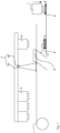
- inline system refers to the fact that a number of processing stations, namely at least those mentioned above, are arranged in a predetermined order, and sheet metal fed into the inline system, for example electrical steel, is processed automatically and sequentially at the predetermined stations.
- the cutting means is used to form structures of the lamella to be produced. This can be done, for example, in several steps with one cutting means or in several steps with different cutting means, whereby in both cases a multi-step structure formation preferably takes place in a lamella from the inside to the outside, i.e.: a number of several required cutting processes are preferably provided in such a way that the cutting processes first form the innermost structures in a lamella and then cutting processes take place step by step towards the outside of the lamella.
- the cutting means can be designed as a punch, for example.
- the cutting in step C) is in this case punching.
- the cutting means can also be designed as a laser.
- the cutting in step C) is then laser beam cutting.
- the inline system can also have a sequence of several cutting means, for example designed as a punching tool with several sequentially arranged punching stages or as a sequence of a punching tool and a laser.
- the at least one cutting means can be designed as a progressive tool with which the predetermined geometry of the lamination is punched into the electrical strip, preferably from the inside of the lamination to the outside of the lamination.
- lamella refers to a shaped part obtained by cutting out the sheet metal, in particular a shaped part obtained by punching.
- the activating agent for activating the adhesive coating is capable of introducing heat into the Adhesive coating, whereby the generation of the heat input can in principle be carried out in any manner.
- the activation agent can have a means for emitting infrared radiation, for example an NIR emitter, i.e. a light source that is designed to emit electromagnetic radiation in the NIR wavelength spectrum, i.e. with wavelengths between 400 nm and 10 ⁇ m, preferably between 780 nm and 3 ⁇ m.
- the activating agent may comprise inductive heating, in particular induction coils, for heating the adhesive coating.
- the inline system has a separating means.
- This separating means is preferably designed as a cutting punch, which sequentially separates the lamellae from the sheet metal that borders the outside of the lamellae by applying a force perpendicular to the sheet metal surface and preferably, in the same process step, conveys the lamellae into a receiving device arranged underneath the sheet metal, in which the lamellae are collected.
- the cutting punch preferably punches the lamella out of the sheet metal at its outer border.
- the cutting means and separating means are part of the same press, with the advantage that the punching and pressing processes are highly synchronized.
- a molded part is cut out of the sheet metal provided in step A, for example punched out in one or more steps, for example a rotor lamella or a stator lamella.
- an electrical component in particular a molded part designed as a stator lamella or a rotor lamella, is cut from the sheet metal provided in step A using the cutting means, whereby the outer contours are preferably not yet formed, but are only formed in step E).
- the molded part In this case, following step C), it has all contours except its outer contour.
- an embodiment can be provided in which the cutting of the molded part also includes the cutting of the outer contour.
- step D) Activating the adhesive coating, preferably activating the adhesive coating over the entire surface, using the activating agent to activate the adhesive coating of the molded part.
- the molded part formed in step C) is preferably activated, i.e.: the activation of step D) takes place after the cutting of step C).
- the heat input activates the adhesive coating and the punched-out molded part is able to form an adhesive bond, i.e. a pre-fixation.
- pre-fixation refers to the fact that the molded part is sufficiently resilient for further processing, but that there is not yet sufficient fixation for the industrial use of the finished sheet stack.
- the adhesive bond is at least partially chemically hardened and its final strength can be increased in a later process by subsequent compaction under pressure and/or temperature.
- the activation temperature in the inline system is between 30 degrees Celsius and 180 degrees Celsius, preferably between 40 degrees Celsius and 120 degrees Celsius, particularly preferably between 50 degrees Celsius and 100 degrees Celsius.
- the positioning area serves to position and/or angle-align the molded part on other molded parts that are already present in the positioning area. This ultimately creates a stack of molded parts aligned against each other and coated with activated adhesive, increasing sequentially, molded part by molded part. provided molded parts.
- the separation of the lamella from the sheet with the separation means preferably carried out as a punching, preferably takes place in the same process step as the placement of the molded part in the positioning area, that is: the separation of step E) and the preferably gluing of the lamella to the previous lamella, comprising the placement of step F), preferably take place in the same process step and with the separation means guiding and, if necessary, exerting pressure on the molded part stack being formed.
- the positioning area can be, for example, a cylindrical tube adapted to the external geometry of the molded part, for example, in the case of molded parts inscribed in a circle, a circular cylindrical tube which lies below the transport plane of the molded part.
- the molded part is aligned by the positioning area, for example designed as a cylindrical hollow tube with a jacket cross-section which essentially corresponds to the cross-section of the molded parts and is aligned with it in the intended position.
- the positioning area can also correspond to an image of the lamella and thus be in full contact with the positioning area.
- Steps C) to F) are repeated in the intended order, for example in the order C)->D)->E)->F) or in the order C)->D)->E) together with F), whereby the stack of molded parts is continuously stacked, i.e. molded parts are continuously positioned in the positioning area. This is preferably done in such a way that the positioning area is continuously completely filled.
- the entire process can also be multi-row, i.e. two or more than two laminations are punched out of an electrical strip in parallel and/or one behind the other (diagonally offset or rotated to each other depending on the number, geometry and arrangement)
- the next molded part is then provided with a treatment fluid at least in some areas by means of a treatment device, so that the effect of the adhesive coating, i.e. the adhesive strength, is reduced, i.e. it has less or no adhesive strength, so that the adhesive coating at this position improves the separability of a stack section below the reduced-effective adhesive coating from a stack section above the reduced-effective adhesive coating.
- the separability is present at the adhesive coating, so that the adhesive coating is provided as a predetermined breaking point at which the lamellae immediately adjacent to the adhesive coating can be easily separated from one another.
- steps C) to F) are repeated continuously, a treatment fluid is applied to selected molded parts at least in some areas using a treatment device, so that the effect of the adhesive coating, i.e. the adhesive strength, of these selected molded parts is reduced and a stack section below the reduced-effective adhesive coating can be easily separated from a stack section above the reduced-effective adhesive coating.
- the molded parts are selected as selected molded parts in such a way that the resulting stack section with a desired number of molded parts and thus a desired molded part height can be separated from the positioning device, below the receiving side of the positioning device, during continuous continuation of the process and is thus provided as a sheet metal package.
- a stack of molded parts is continuously formed which is divided into stack sections, wherein, preferably continuously, each stack section is separated from the stack of molded parts as a sheet metal package.
- each molded part that is placed on the molded part stack at the top of the positioning area a movement out by the thickness of a molded part takes place at the bottom and that as soon as a complete stack section is output at the bottom, it is separated and then made available as a sheet metal package, while the top is continuously filled up.
- the heating i.e. the activating agent
- the heating in the area in which the treatment fluid is applied can also be deactivated, preferably only temporarily when treating the selected molded part.
- step F) The at least partial provision of the molded part with the treatment fluid takes place before step F) but preferably before step E), furthermore preferably after step C), particularly preferably after step D), thus particularly preferably as an additional step between step D) and step E).
- the molded part is provided with the treatment fluid over the entire surface of one of its surfaces; alternatively, the molded part is provided with the treatment fluid over the entire surface of both of its surfaces.
- One variant provides for the treatment fluid to be applied to one of the surfaces of the molded part, namely the surface opposite the release agent. This has the advantage that an unintentional transfer of the treatment fluid via the release agent to a subsequent molded part is avoided.
- the specified number achieved is to be understood in such a way that several specified numbers can be specified, after which a reduction in effect is brought about, so that until the desired number of molded parts is reached, depending on the specification or specifications, the achievement of the A reduction in effectiveness is then achieved.
- a stack of molded parts is then present which has at least one predetermined breaking point, or in a case in which several predetermined numbers were specified: several predetermined breaking points.
- the stack of molded parts can be divided into two or more stack sections, which preferably takes place continuously during the ongoing process. How many predetermined breaking points the stack of molded parts has before a sheet metal package is separated depends solely on the height of the stack sections and the height of the positioning area.
- the treatment device is preferably arranged behind the activating agent, i.e. arranged in such a way that a molded part first passes through the activating agent and then the adhesive coating is treated.
- the treatment device is arranged behind the cutting means but in front of the activating means.
- a stack of molded parts is formed in the positioning area up to a specified total height, whereby the stack of molded parts is available as a sheet metal package when the total height is reached, i.e. with the desired number of molded parts, which has a number of one predetermined breaking point or several predetermined breaking points.
- a predetermined breaking point is characterized by the fact that the adhesion of two adjacent molded parts is lower than the adhesion of two adjacent molded parts outside a predetermined breaking point.
- the predetermined breaking points are formed in the manner described above by reducing the effect of the adhesive, i.e. its possible adhesive force, after a predetermined number of molded parts. This can also be repeated several times when forming a stack of molded parts in the positioning area.
- a stack of molded parts having a desired number N of molded parts can be broken after each N/n reached Molded parts have a predetermined breaking point, which means that the adhesive coating is less effective for every N/nth molded part, with the result that the molded part stack has (n-1) predetermined breaking points and can be divided into n smaller stack sections.
- N is an integer divisible by the integer n.
- the stack sections are removed separately from a stack of molded parts, whereby, depending on the adhesive strength still present between two stack sections, the stack sections are separated at the reduced-effective adhesive coatings that act as predetermined breaking points, for example manually.
- the individual stack sections are then available as a finished laminated core, for example as a finished stator, as a finished rotor or as a finished segment of a stator or rotor.
- a special design with fully bonded sheet metal lamellas has the advantage that sealed cooling channels can be integrated. This is particularly advantageous if different or even incompatible cooling media are used in several electrical components (e.g. rotor and stator).
- the cooling channels can be punched into the lamella or provided between the laminated core and the adjacent component, for example the shaft or housing.
- stator and possibly also a rotor can also be composed of several segments.
- Step G) therefore provides that a predetermined breaking point or several predetermined breaking points are created in the stack of molded parts filling the entire positioning area, wherein the predetermined breaking point or the predetermined breaking points are created by subjecting a molded part located at the predetermined breaking point to an additional step during the passage of steps C) to F).
- the additional step consists in providing the molded part located at the predetermined breaking point with a treatment fluid at least in some areas, preferably over the entire surface, to reduce the effectiveness of the adhesive coating of this molded part.
- the molded part coated with the treatment fluid can be provided with the treatment fluid on only one surface. This surface then lies on the predetermined breaking surface of the molded part.
- the molded part coated with the treatment fluid can be provided with the treatment fluid on both surfaces.
- the molded part then rests on two predetermined breaking surfaces, the molded part serves as a sacrificial lamella that is not part of a stack section.
- sheet generally refers to a rolled product made of a metallic material and, in addition to a thin sheet or a heavy plate, can also refer to a metal strip, a metal strip or metal sheet made of a soft magnetic material, a steel strip or an electrical strip. Other sheet manufacturing processes can optionally be used.
- the laminated core is preferably either a stator core or a rotor core.
- the laminated core consists of so-called laminations, which is why it could also be referred to as a lamination core.
- the activating agent has a first infrared illuminant.
- the first infrared illuminant illuminates the adhesive coating with infrared radiation and activates it through the heat input.
- a temperature sufficient for activation is brought about in the sheet and in particular in the adhesive, for example by illumination for a period of between 0.05 and 1 second at an emission power required to reach the activation temperature, which in turn naturally depends on the precise selection of the adhesive and the nature, in particular the surface and the material, of the molded part and can be easily determined by the person skilled in the art entrusted with implementing the invention.
- the activation means or means are arranged between the cutting means and the separating means and have at least one upper infrared lamp which is directed in a punching direction onto the first sheet surface.
- the activation means has at least one lower infrared lamp which is located beyond the side of the sheet on which the cutting means is located and is directed against a punching direction.
- both at least one upper and at least one lower infrared lamp can be provided.
- the infrared lamp or lamps do not necessarily have to be aligned at a right angle to the slat surface, but can also be aligned at a different angle.
- the activation means has a second infrared illuminant.
- the first infrared illuminant and the second infrared illuminant emit infrared radiation of different wavelengths to activate the adhesive coating with different activation depths.
- the first infrared illuminant has infrared radiation with a wavelength between 780 nm and 1200 nm and/or the second infrared illuminant has infrared radiation with a wavelength between 1200 nm and 3000 nm.
- Such an arrangement can also be referred to as double activation. This can be carried out on one or both sides.
- the activating agent can comprise induction heaters with the advantage that when the sheet is inductively heated, the adhesive is activated starting from the adhesive surface of the sheet with the adhesive coating, so that good activation and subsequent adhesion of the adhesive is achieved.
- the tape is preheated before it is fed into the cutting media, for example by means of inductive heating.
- the advantage of preheating is also a reduction in the press force with the known advantages and a lower forming performance with a lower introduction of residual stresses. This effect can be achieved particularly well if additional optional adjustments to the cutting tools that are familiar to the expert are also carried out.
- steps B) to E) are carried out within an enclosure of the inline system in order to keep the introduced heat as far as possible in the overall system, with the advantage of higher energy efficiency of the overall process.
- the inline system, belt inlet and booster station can be actively heated, either in sections or completely.
- the oil heating of the press stand and tool holder that is usually used is expanded to include heating of the tool, booster station and/or interior, for example by means of a fan with an electric heating cartridge, preferably in countercurrent.
- the activation temperature in the inline system is between 30 degrees Celsius and 180 degrees Celsius, preferably between 40 degrees Celsius and 120 degrees Celsius, particularly preferably between 50 degrees Celsius and 100 degrees Celsius, and that in the post-compressor station a post-compression is carried out at a temperature that is higher than the activation temperature.
- the treatment device has a Coating unit with which the molded part is coated at least in some areas with a treatment fluid that is applied to the adhesive coating as a treatment of the adhesive coating.
- the treatment fluid serves to reduce the effect of the adhesive on a molded part selected for this purpose after a predetermined number of molded parts have been reached, so that the resulting molded part stack has a type of predetermined breaking point at this point that separates two stack sections arranged on top of one another.
- the coating unit can, for example, be an application roller or a roller unit made up of two counter-rotating application rollers that travel parallel or perpendicular to the transport direction of the molded parts in the inline system over a molded part selected for this purpose to coat it.
- the selected molded part is provided with the treatment fluid on one side or both sides. If the molded part is coated with the treatment fluid on both sides, the molded part can be separated from a stack section on both sides and can then be removed as scrap without any further function.
- the entire surface of the molded part is coated with the treatment fluid.
- a punching oil is applied to the adhesive coating as a treatment fluid with the advantage of being inexpensive to obtain and the additional suitability due to the fact that punching oil is inevitably used in the process anyway, so that no undesirable reactions are to be expected due to the use of a different additional substance.
- the punching oil is a self-evaporating punching oil.
- a non-water-miscible cooling lubricant for example, can be used as a punching oil, in particular a medium-viscosity metalworking oil for non-cutting forming.
- an oil free of chlorine and heavy metals such as barium, is used, which is suitable for deep-drawing operations and ensures a homogeneous lubricating film due to its adhesive and wetting properties.
- the oil also preferably has a viscosity of 80 to 110 mm 2 /s, preferably 90 to 100 mm 2 /s at 40 °C and a flash point of > 150 °C, preferably > 170 °C.
- the oil contains phenol and isopropylated phosphate, preferably in a ratio of 3:1, and optionally triphenyl phosphate in a proportion of 5 percent by weight.
- an oil such as that sold by Castrol under the brand name Iloform FST 16 at the time of filing this application can be used.
- a light source can be used to overexpose the adhesive coating as a treatment for the adhesive coating.
- an infrared light source used for activation can be used for overexposure by briefly increasing the light output of the infrared light source for a molded part selected for this purpose, for example by means of a system control system, and/or increasing the dwell time of the molded part under the infrared light source by temporarily slowing down or temporarily stopping the transport of the molded parts.
- a cooling liquid for example liquid nitrogen
- a humidification unit as a treatment for the adhesive coating.
- the molded parts are deposited according to the invention, preferably they are also pressed with an axial force, i.e. a force pointing perpendicular to the flat surface, either after each molded part has been deposited, or after a certain predetermined number of molded parts have been deposited, or after the molded part stack has been formed, for example by means of a pressing stamp.
- the axial force supports the resulting forces, but is significantly lower than the forces applied during any subsequent compaction.
- the stack section is re-compacted in a press with a front-side pressure, that is to say perpendicular to the lamella surface, preferably constant over the front side, of between 10,000 N/(14,000 mm 2 ) and 200,000 N/(10,000 mm 2 ), preferably between 50,000 N/(14,000 mm 2 ) and 150,000 N/(10,000 mm 2 ), at a temperature of the molded part stack of between 30 degrees Celsius and 180 degrees Celsius, preferably between 40 degrees Celsius and 120 degrees Celsius, particularly preferably between 50 degrees Celsius and 100 degrees Celsius.
- a front-side pressure that is to say perpendicular to the lamella surface, preferably constant over the front side, of between 10,000 N/(14,000 mm 2 ) and 200,000 N/(10,000 mm 2 ), preferably between 50,000 N/(14,000 mm 2 ) and 150,000 N/(10,000 mm 2 ), at a temperature of the molded part stack of between 30 degrees Celsius and 180 degrees Celsius, preferably between 40 degrees Celsius and 120 degrees Celsius, particularly
- the compaction thus takes place in a two-stage process, the first stage being the formation of the molded part stack of step F) or the formation of a stack section of the molded part stack of step F) and the second stage being the re-compaction. It has been shown that two-stage compaction results in a significant increase in adhesion, namely approximately doubling the force required to separate a stack section in a head tensile test. Example measurements are described below. Other proven benefits include improved heat dissipation and an increase in the shear strength of the entire composite by more than 5 percent.
- the temperature of the molded part stack between 30 degrees Celsius and 180 degrees Celsius, preferably between 40 degrees Celsius and 120 degrees Celsius, particularly preferably between 50 degrees Celsius and 100 degrees Celsius is preferably maintained by the positioning device by means of a heat input generating illuminant, optionally arranged in or next to the separating means and/or by means of an induction device arranged on the positioning device, the stack of molded parts is heated and the residual heat resulting from this heating is used in the above-mentioned area during subsequent compaction.
- the compaction step is carried out by compressing the laminated core in an axial direction with a uniform surface pressure on the front side, i.e. in a direction perpendicular to the surface of the lamella.
- the compression ensures that the adhesive bond between the individual molded parts is produced particularly well and thus contributes to the longevity of the laminated core.
- the subsequent compaction step preferably takes place outside the press in a downstream compaction station.
- compression can be carried out with displacement control instead of force control. This is achieved, for example, by an adjustable stop.
- displacement control instead of force control.
- the axial length of the components can be set very precisely.
- the compaction step can also be carried out by pressure of the release agent, preferably over part or all of the surface.
- the very good mechanical strength of the sheet metal package achieved through bonding and subsequent compaction is particularly advantageous, which means that machining, for example, can be carried out much more easily and precisely.
- the requirements that increase with the rotational speed or peripheral speed can therefore be met more easily.
- Another advantage is a high degree of design freedom.
- the process is particularly preferably carried out using a sheet metal where the adhesive coating has been applied to the sheet metal as an aqueous dispersion.
- the advantage of an aqueous dispersion is that the coating system is free of organic solvents (VOC-free).
- the coated sheet dries almost tack-free, so that it can be wound into a coil without the individual windings sticking together. Subsequent chemical cross-linking under pressure and temperature is still possible.
- Solvent-containing dissolved epoxy resin systems are generally not sufficiently high molecular weight to dry tack-free, with the disadvantage that the individual windings in the coil are difficult to unwind, if at all, which prevents them from being used in a subsequent process.
- One embodiment therefore particularly preferably provides that the applied adhesive coating was not dissolved in an organic solvent.
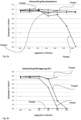
- the adhesive coating preferably consists of an adhesive which, compared to commercially available baked varnish systems known to those skilled in the art, has a significantly higher viscosity, in particular a significantly higher complex viscosity immediately before the onset of chemical crosslinking, under comparable baking conditions, which is illustrated by the test results presented below.
- an adhesive which is not a hot melt adhesive that is to say preferably an adhesive which does not become liquid at the activation temperatures of up to 180 degrees Celsius as described above.
- an adhesive which has a complex viscosity of 8 Pa x s or higher, preferably 10 Pa x s or higher, immediately before the onset of chemical crosslinking, i.e. for example: in a "complex viscosity (temperature)" curve at the location of the local minimum that is closest to the temperature range of chemical crosslinking.
- An adhesive which does not fall below the complex viscosity mentioned, at least at a temperature below a temperature at which chemical crosslinking begins, leads in a method according to the invention or its developments to the fact that no large-scale liquefaction of the adhesive takes place, but rather the adhesive becomes pasty at most at the temperatures used, in particular at the activation temperatures used.
- Such a sheet stack is also particularly suitable for carrying out a method with a post-compaction step, which additionally promotes the high degree of dimensional stability in the geometry.
- the adhesive preferably comprises 1 to 10 parts by weight of the latent hardener, particularly preferably 2 to 5 parts by weight of the latent hardener.
- latent hardener refers to a substance which serves to harden the epoxy resin, but must be activated for hardening, in particular by adding chemical and/or thermal energy.
- the latent hardener is added to the adhesive, for example as a solid in powder form.
- latent accelerator refers to a substance that accelerates the hardening of the epoxy resin by the latent hardener.
- the attribute latent also refers in connection with the accelerator to the fact that the accelerator must first be activated by chemical and/or thermal energy in order to fulfill its function.
- the latent accelerator is added to the adhesive, for example, as a solid in powder form.
- composition given above refers to the mixture of the components present as solids in the parts by weight given to form an adhesive mixture which, in dispersion and/or solution with a suitable liquid, becomes the adhesive which can form an adhesive coating.
- the adhesive with the given components is preferably present as a dispersion of the composition given above in a dispersion medium, in particular as an aqueous dispersion.
- the sheet coated with the adhesive serves as a precursor for flexible, adaptable manufacturing processes for electromagnetic components, in particular stator packs or rotor packs.
- the adhesive function can be carried out at a desired time or at a desired process step after removing lamellae from the sheet, for example by punching.
- the lamellae must be bonded to the sheet after activation (optionally preferably also under partial or full-surface pressure in the press and/or in a downstream compaction process) so that they are bonded together during the chemical curing reaction. This is the only way to produce flawless, non-delaminated and geometrically accurate, mechanically stable packages.
- the sheet has a surface with a potentially short activation time of, for example, 0.05 to 1 second, preferably 0.3 to 1 second.
- a potentially short activation time for example, 0.05 to 1 second, preferably 0.3 to 1 second.
- the epoxy resin present in the adhesive described comprises one or more epoxy resin components with more than one epoxy group, of which preferably at least one epoxy resin has a softening point greater than 50 degrees Celsius.
- the epoxy resins can be aliphatic, cycloaliphatic or aromatic epoxy resins.
- Aliphatic epoxy resins contain components that carry both an aliphatic group and at least two epoxy resin groups.
- Examples of aliphatic epoxy resins can be butanediol diglycidyl ether, hexanediol diglycidyl ether, dimethylpentane dioxide, butadiene dioxide, diethylene glycol diglycidyl ether.
- Cycloaliphatic epoxy resins are, for example, 3-cyclohexenylmethyl-3-cyclohexylcarboxylate diepoxide, 3,4-epoxycyclohexylalkyl-3',4'-epoxycyclohexanecarboxylate, 3,4-epoxy-6-methylcyclohexylmethyl-3',4'-epoxy-o-methylcyclohexanecarboxylate, vinylcyclohexane dioxide , bis(3,4-epoxycyclohexylmethyl)adipate, dicyclopentadiene dioxide, 1,2-epoxy-6-(2,3-epoxypropoxy)hexahydro-4,7-methanoindane.
- Aromatic epoxy resins include bisphenol A epoxy resins, bisphenol F epoxy resins, phenol novolac epoxy resins, cresol novolac epoxy resins, Biphenyl epoxy resins, biphenol epoxy resins, 4,4'-biphenyl epoxy resins, divinyl benzene dioxide, 2-glycidylphenyl glycidyl ether, tetraglycidylmethylenedianiline.
- the epoxy resin is bisphenol A epoxy resin.
- a substance or mixture of substances is used as a latent hardener which preferably enters into hardening reactions with the epoxy resins of the adhesive at temperatures in the range of 80 degrees Celsius to 200 degrees Celsius.
- the hardener may contain dicyandiamides, aziridine derivatives, triazine derivatives, imidazolines, imidazoles, o-tolyl biguanide, cyclic amidines, organic hexafluoroantimonate or hexafluorophosphate compounds or BF3 amine complexes.
- the compounds may be used individually or in combination.
- Examples are 2-methylimidazole, 2-undecylimidazole, 2-heptadecylimidazole, 1,2-dimethylimidazole, 2-ethyl-4-methylimidazole, 2-phenylimidazole, 2-phenyl-4-methylimidazole, 1-benzyl-2-methylimidazole, 1- Benzyl-2-phenylimidazole, 1-cyanoethyl-2-methylimidazole, 1-cyanoethyl-2-undecylimidazole, 1-cyanoethyl-2-ethyl-4-methylimidazole, 1-cyanoethyl-2-phenylimidazole, 1-cyanoethyl-2-undecylimidazolium trimellitate, 1-Cyanoethyl-2-phenylimidazolium trimellitate, 2,4-diamino-6-[2'-methylimidazolyl-(1')]-ethyl-
- the accelerator contains a urea derivative and/or an imidazole.
- the adhesive composition may also contain other components, such as an anti-corrosion additive.
- the hardener contains a dicyandiamide, an imidazole, a BF3-amine complex or a combination thereof.
- the adhesive may contain 1 to 10 parts by weight of a latent accelerator, preferably 1 to 5 parts by weight of a latent accelerator, particularly preferably 1 to 4 parts by weight of a latent accelerator.
- the adhesive further comprises 0.2 to 8 parts by weight, preferably 0.2 to 5 parts by weight, of a dye.
- a dye can be selected from the group of lamp blacks, iron oxide black pigments, or water-soluble dyes, or a mixture of several of the aforementioned.
- the adhesive preferably contains one or more of the insulating additives known to the person skilled in the art, whereby the term insulating additives refers to additives specifically provided to increase the electrical resistance of the adhesive.
- the insulating additives can be used in amounts of 1 to 10 parts by weight, preferably 1 to 5 parts by weight, in the adhesive.
- the adhesive preferably contains one or more of the anti-corrosive additives known to those skilled in the art.
- the anti-corrosive additives can be contained in the adhesive in amounts of 1 to 10 parts by weight, preferably 1 to 5 parts by weight.
- the latent accelerator contains a urea derivative.
- the latent accelerator contained in the adhesive preferably consists of at least 50% by weight, more preferably at least 90% by weight, even more preferably completely, of urea derivative.
- urea derivative preference is given to using an N,N-dimethylurea or an N,N'-dimethylurea or a bifunctional urea derivative, particularly preferably with two urea groups as functional groups, in particular particularly preferably a 4,4'-methylene-bis-(phenyldimethylurea), or a mixture of several of the aforementioned.
- the latent accelerator contained in the adhesive preferably consists of at least 50% by weight, more preferably at least 90% by weight, even more preferably at least 98% by weight, especially preferably completely, of 4,4'-methylene-bis-(phenyldimethylurea).
- an asymmetrically substituted urea is also or exclusively used as the urea derivative.
- a urea derivative in which at least one, preferably 2, particularly preferably 3 hydrogen atoms are replaced by, independently of one another, alkyl groups and/or phenyl groups, which in turn may be substituted.
- the alkyl groups are preferably methyl, ethyl, Propyl or butyl, preferably methyl; the phenyl group is phenyl or a deeply substituted group, preferably in position 4, also preferably as one of the above-mentioned alkyls.
- a difunctional urea derivative is referred to as a derivative as described above which has 2 functional groups.
- Functional groups are groups of atoms which significantly determine the material properties and in particular the reaction behavior of the compound, in particular the functional groups enter into reactions.
- the urea derivative to be used is halogen-free.
- the urea derivative to be used has 2 urea derivatives as functional groups. This advantageously allows epoxy resins to be hardened without the presence of dicyanamides as crosslinkers.
- the average particle size (arithmetic mean) of the urea derivative is preferably between 1 micrometer and 30 micrometers.
- the adhesive coating can be applied to one or both sides of the sheet. If an adhesive coating is applied to both sides, the thickness of the coating can be the same, but different thicknesses can also be provided.
- the preferred thickness of the adhesive coating which means the thickness of the coating on one side for single-sided adhesive or the thickness of the coating on two sides for double-sided adhesive
- Adhesive coating the total thickness of the adhesive coating on both sides added together is between 1 micrometer and 20 micrometers, preferably between 2 micrometers and 10 micrometers. A total thickness between 4 and 8 micrometers is particularly preferred.
- An adhesive coating on one side of the sheet metal results in a simpler production process in terms of equipment, while an adhesive coating on both sides of the sheet metal results in the advantage that when individual lamellae made from the sheet metal are positioned on top of one another, the adhesive surface is positioned next to the adhesive surface, thereby achieving improved adhesion and thus a higher mechanical stability of the electromagnetic component, which has been demonstrated in tests.
- the first partial coating of the first sheet surface and the second partial coating of the second bleaching surface are adapted to one another with a second thickness such that the first thickness is at least 1.5 times, preferably 2 times, the second thickness.
- the first thickness is responsible for excellent insulation, so that the risk of adhesive gaps is almost negligible, while the thinner of the two, namely the second partial coating applied with the second thickness, essentially serves to produce the excellent adhesion.
- a double-sided coating with a total thickness of both coatings between 4 and 6 micrometers is particularly preferred.
- Such a low coating thickness is possible with the methods carried out according to the invention or in accordance with further developments of the invention due to their high reactivity, as the examples produced demonstrate.
- Known bonding varnish adhesives generally require higher coating thicknesses than 6 micrometers (e.g. bonding varnish on both sides, 5 ⁇ m per side). This leads to the advantage that Tests carried out according to the invention with the sheets in one of the types described have shown that stators or rotors in particular can be produced which have a significantly higher iron filling factor than components produced using the baked enamel process. The advantage is a slightly higher efficiency of the electrical machine having the component.
- adhesive coatings between a total of 1 and 20 micrometers, preferably 2 and 8 micrometers, can be provided.
- a pretreatment, an adhesion promoter, a phosphating and/or an insulator, for example in the form of an insulating lacquer layer, is arranged between the sheet and the adhesive layer and/or only insulating lacquer is arranged on the side of the sheet opposite the adhesive layer or the surface is uncoated.
- the non-grain-oriented electrical steel strip or the non-grain-oriented sheet has a yield strength in the longitudinal direction under standard normal conditions of 190 to 610 MPa and a maximum tensile strength of 310 to 740 MPa and a minimum elongation at break A80 of 6 to 48% measured in accordance with DIN EN ISO 6892-1 as well as a hardness Hv5 of 100-250.
- the material has a yield strength in the longitudinal direction at room temperature of 310 to 600 MPa and a maximum tensile strength of 400 to 640 MPa as well as an elongation at break A80 of 7 to 32% measured in accordance with DIN EN ISO 6892-1 and a hardness Hv5 of 130-250.
- the material preferably has an anisotropy at P1.0; 400 Hz in the range of 5 to 17%.
- Suitable and preferred sheets are those used, particularly electrical steel, with a thickness of between 0.05 and 2.5 mm, with thicknesses between 0.1 and 1.0 mm being preferred. Thicknesses between 0.15 and 0.4 mm are particularly preferred.
- the sheet can be a multi-layer composite (sandwich) made of a sheet layer, for example one of the electrical tapes described above, and one or more additional layers, for example with an acoustically dampening functional layer (e.g. bondal E).
- the sheet can also be coated on one or both sides with an acoustically dampening functional layer (e.g. half-bondal E), so that the adhesive system described bonds directly to the acoustically dampening functional layer (e.g. chemically based acrylate). It is known from technology that epoxy resin systems have good compatibility.
- the sheet metal can have an acoustically dampening functional layer on one side and an adhesive layer on the opposite side of the sheet metal.
- steps C) to F) of the method according to the invention are carried out with a stroke rate of at least 80/min, preferably between 120/min and 300/min.
- a stroke rate significantly above 300/min can also be achieved.
- One idea of the invention relates to a laminated core or a stack section of a laminated core for an electrical machine, which is produced using a method of the type described above or one of its developments.
- the laminated core or the stack section is designed as a stator or as a rotor.
- the invention comprises an electrical machine, in particular an electric motor, which has a stator and/or a rotor which was produced using a method according to the invention or one of its developments.
- the electric machine has a stator and a rotor, the stator being partially or completely a laminated core that is produced using the method according to the invention or one of its further developments, and the rotor being partially or completely a component produced using expert stamping and packaging.
- the stator which is particularly demanding in terms of electromagnetic efficiency, is thus provided with excellent electromagnetic properties, while the rotor, which is less demanding in terms of its electromagnetic properties in many applications, is produced using conventional stamping and packaging, which is very cost-effective. It is therefore an electrical machine is provided that offers a good trade-off between good electromagnetic properties and cost-efficient production.
- FIG.1 An example of a first embodiment of the method for producing a laminated core for an electric motor is shown in Fig.1
- a sheet already coated with an adhesive is provided, namely as a non-grain-oriented electrical strip 1, coated with an adhesive of the type provided according to the invention.
- This strip is transported into an inline system.
- a number of cutting means 4 designed as punches ensure that molded parts 2 are cut, which are designed as rotor lamellas or as stator lamellas.
- the molded part is illuminated by means of a means designed as an NIR emitter for emitting infrared radiation 5, and the adhesive coating of the molded part is activated by the heating caused thereby.
- the activation means 5 has a first infrared illuminant 5a and a second infrared illuminant 5b.
- the illuminant 5a emits radiation with wavelengths of 780 nm and 1200 nm, while the second illuminant emits radiation with wavelengths of 1200 nm and 3000 nm.
- the treatment device 9 designed as a coating roller is used to coat certain lamellae in order to act as a predetermined breaking point between individual sheet metal packages in the subsequent stack of molded parts.
- the coating roller 9 moves to the sheet metal whenever a predetermined number of molded parts has completed the activation of the adhesive coating, in the illustration shown into the plane of the paper, and coats the molded part that follows the predetermined number in order to reduce or completely eliminate the effect of the adhesive coating.
- the coated molded part then has a predetermined breaking point at which the molded part stack can be separated into stack sections, preferably in a continuously running process, and each of the stack sections represents the finished sheet metal package.
- the lamella 8 was a lamella that corresponded to a predetermined number of molded parts. For this reason, it was coated with a punching oil using the coating roller 9 designed as a treatment device, and thus has a reduced adhesive strength.
- the molded part is then pressed out with the separating means 6 designed as a cutting stamp and collected in a positioning area to form a stack 3 in a positionally and/or angularly aligned manner and pre-fixed, i.e.: the lamellae provided with an activated adhesive coating already adhere to one another due to their own weight.
- the sheet metal package is the stack section of the molded part stack removed at the predetermined breaking point 8, which has a reduced-effective adhesive coating on the lamella 8.
- the stack sections can be removed either by their own weight or by separated from the molded part stack using equipment or manual assistance. In the present example, there are two separate stack sections, which are further compacted in a subsequent step as stack section 3' in the compaction station 7.
- compaction is carried out in a compaction station with a compaction stamp 7 until the adhesive has hardened and the finished sheet metal package can be removed.
- Circuit boards made of electrical steel M800-50A (according to EN 10027-1) with the material code 1.0816 (according to EN 10027-2), thickness 0.5 mm, length x width: 200 x 150 mm.
- Samples 0, 1, 2 and 3 were prepared. Samples 0, 1 and 2 are a control sample, they are coated with a non-favorable adhesive.
- Sample 3 is an advantageous sample.
- the samples produced are blanks of the above type coated with adhesive using a roller according to the following parameters: Sample designation Parts by weight of epoxy resin (present as solid resin) Hardener parts by weight Accelerator weight parts Selected accelerator Sample0 60 3.5 4.5 Conventional accelerator (DYHARD URAcc57, brand name) Sample1 60 3.5 3.0 Conventional accelerator (DYHARD URAcc13, brand name) Sample2 60 3.5 3.0 Conventional accelerator (DYHARD URAcc13, brand name) Sample3 60 3.5 3.0 4,4'-Methylenebis-(phenyldimethyl urea) Layer thicknesses Sample0: 1st surface: 6 ⁇ m, 2nd surface 0 ⁇ m, Sample 1: 1st surface: 6 ⁇ m, 2nd surface 0 ⁇ m, Sample 2: 1st surface: 4 ⁇ m, 2nd surface 2 ⁇ m, Sample 3: 1st surface: 4 ⁇ m, 2nd surface 2 ⁇ m. Several specimens were produced for each type of sample. To test the long-term stability,
- sample 3 has the best storage stability with a virtually unchanged good shear value after 4 weeks of storage at 40 degrees Celsius.
- the only sample obtained was a board sandwich that still had an unchanged good shear value even after four weeks of storage at 40 degrees Celsius. At the time of registration, the tests were still ongoing.
- Tests were also carried out on the finished sandwiches; they were heated to test temperatures and then, after being kept under heat for a short time, also subjected to a shear test.
- Sample number Sample 2 Sample3 Shear values [N/mm 2 ] Average value from triplicate tests [N/ mm2 ] Standard deviation [N/ mm2 ] Standard deviation RT 5.55 0.88 6.01 0.26 50 degrees Celsius 5.08 1.32 5.85 0.11 100 degrees Celsius 5.38 0.27 5.59 0.12 150 degrees Celsius 4.89 0.42 5.22 0.08 200 degrees Celsius 4.66 0.46 4.96 0.04
- Sample 0 was subjected to temperature testing as a reference, and it was shown that after heating to 150 degrees Celsius, a shear value of about 0.90 N/mm 2 was obtained. Based on sample 3, it was thus shown that the advantageous sheets are suitable for the production of more temperature-stable sheet packages compared to already known sheets.
- the advantageous adhesive having the composition as used in sample 3
- the complex viscosity immediately before the chain reaction with a value of 10.74 Pa xs, is significantly higher than the values achieved with a conventional baking varnish.
- the method according to the invention can be used and in particular also for its further development, which provides for subsequent compaction, since the adhesive does not liquefy, but at most a transition to a pasty behavior occurs. This means that no significant flow of adhesive out of the sheet stack can be observed, with the corresponding advantages, in particular for good adhesion, which can be proven, for example, with head tensile tests.
- sample 3 was qualitatively equivalent to each of the samples 0 to 2 in terms of its oil resistance, i.e.: in shear value tests, no reduction in the adhesion of the lamellae to one another was found after 70 days of storage in an oil at 150 degrees Celsius.
Landscapes
- Engineering & Computer Science (AREA)
- Power Engineering (AREA)
- Manufacturing & Machinery (AREA)
- Dispersion Chemistry (AREA)
- Electromagnetism (AREA)
- Chemical & Material Sciences (AREA)
- Physics & Mathematics (AREA)
- Adhesives Or Adhesive Processes (AREA)
- Manufacturing Cores, Coils, And Magnets (AREA)
- Manufacture Of Motors, Generators (AREA)
- Laminated Bodies (AREA)
- Epoxy Resins (AREA)
- Container, Conveyance, Adherence, Positioning, Of Wafer (AREA)
Applications Claiming Priority (3)
| Application Number | Priority Date | Filing Date | Title |
|---|---|---|---|
| DE102020109985.1A DE102020109985A1 (de) | 2020-04-09 | 2020-04-09 | Verfahren zum Herstellen eines Blechpakets, Blechpaket und Elektrische Maschine |
| EP21702198.9A EP4062523A1 (fr) | 2020-04-09 | 2021-01-25 | Procédé pour la fabrication d'un empilement de stratification, empilement de stratification et machine électrique |
| PCT/EP2021/051570 WO2021204433A1 (fr) | 2020-04-09 | 2021-01-25 | Procédé pour la fabrication d'un empilement de stratification, empilement de stratification et machine électrique |
Related Parent Applications (1)
| Application Number | Title | Priority Date | Filing Date |
|---|---|---|---|
| EP21702198.9A Division EP4062523A1 (fr) | 2020-04-09 | 2021-01-25 | Procédé pour la fabrication d'un empilement de stratification, empilement de stratification et machine électrique |
Publications (2)
| Publication Number | Publication Date |
|---|---|
| EP4418507A2 true EP4418507A2 (fr) | 2024-08-21 |
| EP4418507A3 EP4418507A3 (fr) | 2025-01-08 |
Family
ID=74347060
Family Applications (3)
| Application Number | Title | Priority Date | Filing Date |
|---|---|---|---|
| EP21702198.9A Pending EP4062523A1 (fr) | 2020-04-09 | 2021-01-25 | Procédé pour la fabrication d'un empilement de stratification, empilement de stratification et machine électrique |
| EP24180243.8A Pending EP4418507A3 (fr) | 2020-04-09 | 2021-01-25 | Procédé de fabrication d'un paquet de tôles, paquet de tôles et machine électrique |
| EP24180249.5A Pending EP4432530A3 (fr) | 2020-04-09 | 2021-01-25 | Procédé de fabrication d'un paquet de tôles, paquet de tôles et machine électrique |
Family Applications Before (1)
| Application Number | Title | Priority Date | Filing Date |
|---|---|---|---|
| EP21702198.9A Pending EP4062523A1 (fr) | 2020-04-09 | 2021-01-25 | Procédé pour la fabrication d'un empilement de stratification, empilement de stratification et machine électrique |
Family Applications After (1)
| Application Number | Title | Priority Date | Filing Date |
|---|---|---|---|
| EP24180249.5A Pending EP4432530A3 (fr) | 2020-04-09 | 2021-01-25 | Procédé de fabrication d'un paquet de tôles, paquet de tôles et machine électrique |
Country Status (7)
| Country | Link |
|---|---|
| US (1) | US12381458B2 (fr) |
| EP (3) | EP4062523A1 (fr) |
| JP (3) | JP7386354B2 (fr) |
| KR (1) | KR102881907B1 (fr) |
| CN (1) | CN115461969B (fr) |
| DE (1) | DE102020109985A1 (fr) |
| WO (1) | WO2021204433A1 (fr) |
Families Citing this family (12)
| Publication number | Priority date | Publication date | Assignee | Title |
|---|---|---|---|---|
| DE102019213658A1 (de) * | 2019-09-09 | 2021-03-11 | Elringklinger Ag | Verfahren zur Herstellung eines Blechstapels, Blechstapel, Maschinenbauteil und Elektromotor |
| BR112023021044A2 (pt) * | 2021-04-14 | 2023-12-12 | Nippon Steel Corp | Método e aparelho de fabricação de núcleo colado e empilhado |
| BR112023021167A2 (pt) | 2021-04-14 | 2024-01-16 | Nippon Steel Corp | Método e aparelho de fabricação de núcleo colado e empilhado |
| DE102022116250A1 (de) | 2022-06-29 | 2024-01-04 | Thyssenkrupp Steel Europe Ag | Hocheffiziente Kompressor-Motoren |
| JP7513941B1 (ja) * | 2022-09-08 | 2024-07-10 | 日本製鉄株式会社 | 積層鉄心の製造方法及び製造装置 |
| DE102023101065A1 (de) | 2023-01-18 | 2024-07-18 | Thyssenkrupp Steel Europe Ag | Verfahren zum Herstellen eines Verbunds aus Elektroblechen |
| DE102023118397A1 (de) | 2023-07-12 | 2025-01-16 | Thyssenkrupp Steel Europe Ag | Verbesserungen im Inline-Verarbeitungsprozess von beschichtetem Elektroblech |
| TWI894697B (zh) * | 2023-11-23 | 2025-08-21 | 中國鋼鐵股份有限公司 | 鋼件加熱系統和鋼件加熱方法 |
| CN117791984B (zh) * | 2024-02-27 | 2024-05-17 | 江阴华新精密科技股份有限公司 | 一种采用自粘涂层料带冲压的定转子铁芯制作方法 |
| DE102024117041A1 (de) | 2024-06-18 | 2025-12-18 | Dr. Ing. H.C. F. Porsche Aktiengesellschaft | Verfahren zur Verbindung eines Mica-Bauteils mit einem weiteren Bauteil, Brandschutzeinrichtung und Elektrofahrzeug |
| WO2026073907A1 (fr) | 2024-10-04 | 2026-04-09 | Syensqo Specialty Polymers Usa Llc | Procédé de revêtement à base d'une paek à basse température de fusion |
| CN119298551B (zh) * | 2024-12-10 | 2025-03-14 | 御马精密科技(江苏)股份有限公司 | 一种自粘接无铆点铁芯及其生产工艺 |
Citations (2)
| Publication number | Priority date | Publication date | Assignee | Title |
|---|---|---|---|---|
| GB1293142A (en) | 1969-09-09 | 1972-10-18 | Ciba Geigy Uk Ltd | Curable epoxide resin compositions |
| DE3829068C1 (fr) | 1988-08-25 | 1990-01-11 | Mannesmann Ag, 4000 Duesseldorf, De |
Family Cites Families (27)
| Publication number | Priority date | Publication date | Assignee | Title |
|---|---|---|---|---|
| JPS5774377A (en) | 1980-10-28 | 1982-05-10 | Showa Alum Corp | Method of peeling off adhesive tape from adhesive tape-converted metallic material |
| JPS5847051A (ja) * | 1981-09-14 | 1983-03-18 | Mitsui Petrochem Ind Ltd | エポキシ樹脂変性物およびそれを用いる接着方法 |
| GB2121353B (en) * | 1982-05-28 | 1985-09-11 | Eurobond Coatings Limited | Laminating |
| US4680871A (en) | 1985-05-17 | 1987-07-21 | David Reznik | Apparatus and method for drying and curing coated substrates |
| JPH05304037A (ja) * | 1992-04-28 | 1993-11-16 | Aida Eng Ltd | 積層コアの製造方法 |
| JPH11254642A (ja) | 1998-03-16 | 1999-09-21 | Dainippon Printing Co Ltd | 乾燥装置 |
| JP2001078399A (ja) * | 1999-09-07 | 2001-03-23 | Matsushita Electric Ind Co Ltd | 積層体の製造方法とその装置 |
| DE10324486A1 (de) * | 2003-05-30 | 2004-12-16 | Degussa Ag | Verwendung von Harnstoff-Derivaten als Beschleuniger für Epoxidharze |
| US7421271B2 (en) | 2004-04-12 | 2008-09-02 | Lucent Technologies Inc. | Sector switching detection method |
| JP5026596B2 (ja) | 2008-10-31 | 2012-09-12 | パイオニア株式会社 | スピーカの製造方法 |
| DE102009028180A1 (de) | 2009-08-03 | 2011-02-10 | Henkel Ag & Co. Kgaa | Verfahren zum Befestigen eines Magneten auf oder in einem Rotor oder Stator |
| JP5728831B2 (ja) | 2010-06-03 | 2015-06-03 | 株式会社豊田自動織機 | 充電装置 |
| CN102738976A (zh) | 2011-04-14 | 2012-10-17 | 安泰科技股份有限公司 | 一种电机用非晶合金定子铁芯的制造方法 |
| DE102012001744A1 (de) | 2012-01-28 | 2013-08-01 | Volkswagen Aktiengesellschaft | Verfahren, Vorrichtung und Klebstoff zur Herstellung eines Blechpakets aus mehreren aufeinander gestapelten Elektroblechen |
| DE102012005795A1 (de) | 2012-03-14 | 2013-09-19 | Kienle + Spiess Gmbh | Lamellenpaket und Verfahren zu seiner Herstellung |
| AT512931B1 (de) * | 2012-12-11 | 2013-12-15 | Voestalpine Stahl Gmbh | Blechpaket und Verfahren zum Verbinden von Blechteilen zu einem Blechpaket |
| JP2015174885A (ja) | 2014-03-13 | 2015-10-05 | 三菱レイヨン株式会社 | 接着剤組成物及び接合体 |
| DE102015012172A1 (de) | 2015-09-23 | 2017-03-23 | Universität Kassel | Thermisch aktivierbare, schnellhärtende Klebstoffbeschichtung |
| EP3316457A1 (fr) | 2016-10-27 | 2018-05-02 | voestalpine Automotive Components Deutschland GmbH | Dispositif et procédé de liaison de parties de tôles à un paquet de tôles |
| PL3633830T3 (pl) | 2017-05-23 | 2025-05-05 | Three Bond Co., Ltd. | Sposób wytwarzania laminowanej blachy stalowej |
| WO2019088009A1 (fr) | 2017-11-01 | 2019-05-09 | 日東電工株式会社 | Stratifié et feuille de renfort |
| WO2019088618A1 (fr) * | 2017-11-06 | 2019-05-09 | Hangnam Co., Ltd. | Appareil de fabrication de noyau de stratification d'adhésif par application d'un adhésif à une bande |
| KR102256174B1 (ko) * | 2017-11-06 | 2021-05-26 | 주식회사 비엠씨 | 접착제 코팅 방식의 접착식 적층 코어 제조 장치 |
| US11872619B2 (en) * | 2018-12-18 | 2024-01-16 | Threebond Co., Ltd. | Method for manufacturing laminated steel sheet, apparatus for manufacturing laminated steel sheet, and curable composition used for the same |
| JP7636144B2 (ja) * | 2020-08-07 | 2025-02-26 | トヨタ自動車株式会社 | 蓄電セル冷却構造 |
| JP7626421B2 (ja) * | 2020-09-11 | 2025-02-04 | 清田産業株式会社 | 食品性能改良剤及びこれを用いた食品の製造方法 |
| JP7484669B2 (ja) * | 2020-11-04 | 2024-05-16 | 村田機械株式会社 | 自律走行体の走行教示記憶方法、自律走行体、記録媒体 |
-
2020
- 2020-04-09 DE DE102020109985.1A patent/DE102020109985A1/de active Pending
-
2021
- 2021-01-25 EP EP21702198.9A patent/EP4062523A1/fr active Pending
- 2021-01-25 EP EP24180243.8A patent/EP4418507A3/fr active Pending
- 2021-01-25 CN CN202180027173.0A patent/CN115461969B/zh active Active
- 2021-01-25 JP JP2022557077A patent/JP7386354B2/ja active Active
- 2021-01-25 WO PCT/EP2021/051570 patent/WO2021204433A1/fr not_active Ceased
- 2021-01-25 US US17/910,744 patent/US12381458B2/en active Active
- 2021-01-25 KR KR1020227028883A patent/KR102881907B1/ko active Active
- 2021-01-25 EP EP24180249.5A patent/EP4432530A3/fr active Pending
-
2023
- 2023-11-13 JP JP2023193042A patent/JP2024009070A/ja active Pending
-
2025
- 2025-03-26 JP JP2025051779A patent/JP2025098174A/ja active Pending
Patent Citations (2)
| Publication number | Priority date | Publication date | Assignee | Title |
|---|---|---|---|---|
| GB1293142A (en) | 1969-09-09 | 1972-10-18 | Ciba Geigy Uk Ltd | Curable epoxide resin compositions |
| DE3829068C1 (fr) | 1988-08-25 | 1990-01-11 | Mannesmann Ag, 4000 Duesseldorf, De |
Also Published As
| Publication number | Publication date |
|---|---|
| EP4432530A3 (fr) | 2025-01-15 |
| JP2024009070A (ja) | 2024-01-19 |
| JP2023518098A (ja) | 2023-04-27 |
| JP7386354B2 (ja) | 2023-11-24 |
| DE102020109985A1 (de) | 2021-10-14 |
| CN115461969B (zh) | 2026-03-24 |
| EP4432530A2 (fr) | 2024-09-18 |
| US12381458B2 (en) | 2025-08-05 |
| JP2025098174A (ja) | 2025-07-01 |
| EP4062523A1 (fr) | 2022-09-28 |
| KR102881907B1 (ko) | 2025-11-05 |
| EP4418507A3 (fr) | 2025-01-08 |
| WO2021204433A1 (fr) | 2021-10-14 |
| CN115461969A (zh) | 2022-12-09 |
| US20230119661A1 (en) | 2023-04-20 |
| KR20220129065A (ko) | 2022-09-22 |
Similar Documents
| Publication | Publication Date | Title |
|---|---|---|
| EP4418507A2 (fr) | Procédé de fabrication d'un paquet de tôles, paquet de tôles et machine électrique | |
| EP3895279B1 (fr) | Tôle pour la production d'un paquet de tôles, en particulier un ensemble stator ou un ensemble rotor, et procédé de production d'un paquet de tôles | |
| DE112009004598B4 (de) | Verfahren zum stoffschlüssigen fügen von paketlamellen zu einem weichmagnetischen blechpaket | |
| EP3353241A1 (fr) | Revêtement adhésif thermoactivable à durcissement rapide | |
| DE102012001744A1 (de) | Verfahren, Vorrichtung und Klebstoff zur Herstellung eines Blechpakets aus mehreren aufeinander gestapelten Elektroblechen | |
| DE102019213658A1 (de) | Verfahren zur Herstellung eines Blechstapels, Blechstapel, Maschinenbauteil und Elektromotor | |
| EP4029113A1 (fr) | Procédé de fabrication d'un empilement de feuilles métalliques pour un moteur électrique | |
| WO1997030505A1 (fr) | Procede de fabrication d'un module electromagnetique pour un train a sustentation magnetique | |
| DE102023118397A1 (de) | Verbesserungen im Inline-Verarbeitungsprozess von beschichtetem Elektroblech | |
| EP4244056B1 (fr) | Procédé de raccordement des éléments de tôle à des paquets de tôle | |
| EP4404443A1 (fr) | Procédé de fabrication d'un composite de tôles d'acier électrique | |
| EP4725697A1 (fr) | Procédé continu et dispositif de collage de bandes électriques dans le processus de poinçonnage | |
| EP4659334A1 (fr) | Procédé de fabrication d'un noyau stratifié et noyau stratifié | |
| WO2022008655A1 (fr) | Matériau de liaison, empilement de feuilles métalliques, composant de machine et moteur électrique |
Legal Events
| Date | Code | Title | Description |
|---|---|---|---|
| PUAI | Public reference made under article 153(3) epc to a published international application that has entered the european phase |
Free format text: ORIGINAL CODE: 0009012 |
|
| STAA | Information on the status of an ep patent application or granted ep patent |
Free format text: STATUS: THE APPLICATION HAS BEEN PUBLISHED |
|
| AC | Divisional application: reference to earlier application |
Ref document number: 4062523 Country of ref document: EP Kind code of ref document: P |
|
| AK | Designated contracting states |
Kind code of ref document: A2 Designated state(s): AL AT BE BG CH CY CZ DE DK EE ES FI FR GB GR HR HU IE IS IT LI LT LU LV MC MK MT NL NO PL PT RO RS SE SI SK SM TR |
|
| PUAL | Search report despatched |
Free format text: ORIGINAL CODE: 0009013 |
|
| AK | Designated contracting states |
Kind code of ref document: A3 Designated state(s): AL AT BE BG CH CY CZ DE DK EE ES FI FR GB GR HR HU IE IS IT LI LT LU LV MC MK MT NL NO PL PT RO RS SE SI SK SM TR |
|
| RIC1 | Information provided on ipc code assigned before grant |
Ipc: H02K 15/02 20060101AFI20241202BHEP |
|
| STAA | Information on the status of an ep patent application or granted ep patent |
Free format text: STATUS: REQUEST FOR EXAMINATION WAS MADE |
|
| 17P | Request for examination filed |
Effective date: 20250211 |