EP4420574A2 - Heissluftkochgerät mit mehreren funktionskonfigurationen - Google Patents
Heissluftkochgerät mit mehreren funktionskonfigurationen Download PDFInfo
- Publication number
- EP4420574A2 EP4420574A2 EP24189093.8A EP24189093A EP4420574A2 EP 4420574 A2 EP4420574 A2 EP 4420574A2 EP 24189093 A EP24189093 A EP 24189093A EP 4420574 A2 EP4420574 A2 EP 4420574A2
- Authority
- EP
- European Patent Office
- Prior art keywords
- cooking
- base
- heating block
- container
- hot air
- Prior art date
- Legal status (The legal status is an assumption and is not a legal conclusion. Google has not performed a legal analysis and makes no representation as to the accuracy of the status listed.)
- Pending
Links
- 238000010411 cooking Methods 0.000 title claims abstract description 245
- 238000010438 heat treatment Methods 0.000 claims abstract description 146
- 235000013305 food Nutrition 0.000 claims abstract description 26
- 238000003860 storage Methods 0.000 claims description 16
- 238000003780 insertion Methods 0.000 claims description 10
- 230000037431 insertion Effects 0.000 claims description 10
- 238000007789 sealing Methods 0.000 claims description 8
- 230000000295 complement effect Effects 0.000 claims description 2
- 230000000284 resting effect Effects 0.000 claims description 2
- 230000000903 blocking effect Effects 0.000 description 4
- 239000000463 material Substances 0.000 description 4
- 239000011521 glass Substances 0.000 description 3
- XAGFODPZIPBFFR-UHFFFAOYSA-N aluminium Chemical compound [Al] XAGFODPZIPBFFR-UHFFFAOYSA-N 0.000 description 2
- 229910052782 aluminium Inorganic materials 0.000 description 2
- 230000008901 benefit Effects 0.000 description 2
- 230000009467 reduction Effects 0.000 description 2
- 229910001220 stainless steel Inorganic materials 0.000 description 2
- 239000010935 stainless steel Substances 0.000 description 2
- 230000007704 transition Effects 0.000 description 2
- 241000251468 Actinopterygii Species 0.000 description 1
- 241001465754 Metazoa Species 0.000 description 1
- 230000009471 action Effects 0.000 description 1
- 230000005540 biological transmission Effects 0.000 description 1
- 238000004140 cleaning Methods 0.000 description 1
- 239000011248 coating agent Substances 0.000 description 1
- 238000000576 coating method Methods 0.000 description 1
- 239000012141 concentrate Substances 0.000 description 1
- 235000005911 diet Nutrition 0.000 description 1
- 230000000378 dietary effect Effects 0.000 description 1
- 238000000605 extraction Methods 0.000 description 1
- 235000019688 fish Nutrition 0.000 description 1
- 238000009434 installation Methods 0.000 description 1
- 238000004519 manufacturing process Methods 0.000 description 1
- 235000013372 meat Nutrition 0.000 description 1
- 230000007246 mechanism Effects 0.000 description 1
- 230000000149 penetrating effect Effects 0.000 description 1
- 230000002093 peripheral effect Effects 0.000 description 1
- 235000013550 pizza Nutrition 0.000 description 1
- 238000002360 preparation method Methods 0.000 description 1
- 235000011835 quiches Nutrition 0.000 description 1
- 230000006641 stabilisation Effects 0.000 description 1
- 238000011105 stabilization Methods 0.000 description 1
- 230000009466 transformation Effects 0.000 description 1
- 235000013311 vegetables Nutrition 0.000 description 1
Images




Classifications
-
- A—HUMAN NECESSITIES
- A47—FURNITURE; DOMESTIC ARTICLES OR APPLIANCES; COFFEE MILLS; SPICE MILLS; SUCTION CLEANERS IN GENERAL
- A47J—KITCHEN EQUIPMENT; COFFEE MILLS; SPICE MILLS; APPARATUS FOR MAKING BEVERAGES
- A47J37/00—Baking; Roasting; Grilling; Frying
- A47J37/06—Roasters; Grills; Sandwich grills
- A47J37/0623—Small-size cooking ovens, i.e. defining an at least partially closed cooking cavity
- A47J37/0629—Small-size cooking ovens, i.e. defining an at least partially closed cooking cavity with electric heating elements
-
- A—HUMAN NECESSITIES
- A47—FURNITURE; DOMESTIC ARTICLES OR APPLIANCES; COFFEE MILLS; SPICE MILLS; SUCTION CLEANERS IN GENERAL
- A47J—KITCHEN EQUIPMENT; COFFEE MILLS; SPICE MILLS; APPARATUS FOR MAKING BEVERAGES
- A47J37/00—Baking; Roasting; Grilling; Frying
- A47J37/06—Roasters; Grills; Sandwich grills
- A47J37/0623—Small-size cooking ovens, i.e. defining an at least partially closed cooking cavity
- A47J37/0629—Small-size cooking ovens, i.e. defining an at least partially closed cooking cavity with electric heating elements
- A47J37/0641—Small-size cooking ovens, i.e. defining an at least partially closed cooking cavity with electric heating elements with forced air circulation, e.g. air fryers
-
- A—HUMAN NECESSITIES
- A47—FURNITURE; DOMESTIC ARTICLES OR APPLIANCES; COFFEE MILLS; SPICE MILLS; SUCTION CLEANERS IN GENERAL
- A47J—KITCHEN EQUIPMENT; COFFEE MILLS; SPICE MILLS; APPARATUS FOR MAKING BEVERAGES
- A47J37/00—Baking; Roasting; Grilling; Frying
- A47J37/06—Roasters; Grills; Sandwich grills
- A47J37/0623—Small-size cooking ovens, i.e. defining an at least partially closed cooking cavity
- A47J37/0664—Accessories
Definitions
- the present invention relates to hot air cooking appliances which enable food to be cooked by means of a circulation of hot air, said cooking being carried out using very little oil, or even no oil at all.
- a main objective of the invention is to reduce the size of the hot air cooking appliance so as to facilitate its storage.
- Hot air cooking appliances are well known to those skilled in the art, these being generally called “hot air fryers”. Such a cooking appliance makes it possible to significantly reduce the amount of fat, or even to eliminate it completely, when cooking food, which is done simply by hot air circulating in a cooking chamber containing the food to be cooked. Thus, it is possible to consume more dietetic foods, these foods being able to be of plant or animal origin, for example fries, vegetables, meat or fish.
- a hot air cooking appliance generally comprises a closed base which incorporates a removable tank. This tank allows the reception of the food to be cooked, either directly or by placing this food to be cooked in a removable basket, itself positioned in the tank. Once the food is placed in the tank and the latter placed in the base, the cooking appliance is closed to constitute a cooking chamber incorporating the tank, the possible basket and the food. Hot air then circulates in this cooking chamber by means of a heating block arranged in the upper part of the cooking appliance, above the base, the circulation of the hot air allowing the cooking of the food placed in the tank.
- the heating block comprises a heating device and an air circulation device allowing the circulation of the heated air in the cooking chamber.
- Such a design of hot air cooking appliance has the disadvantage of having a limited number of cooking modes, the tank having to be placed on the base so as to constitute the heating enclosure and to allow the cooking of food by means of a circulation of hot air in said enclosure.
- the invention aims to increase the different types of cooking that can be carried out using a hot air cooking appliance.
- a hot air cooking appliance which comprises a heating block arranged in the upper part and a base arranged in the lower part.
- the heating block comprises a heating device for heating air and a circulation device for moving the heated air.
- the base comprises a housing above which the heating block is mounted to define a first functional configuration of the cooking appliance according to which said housing is capable of receiving a cooking container provided with an upper opening intended to be arranged opposite the heating device.
- the heating block is configured to be placed in a stable manner in an inverted position over the base and comprises support means capable of receiving a cooking container by arranging a bottom of said container opposite the heating device, such that the cooking appliance has a second functional configuration allowing the cooking of food in a container placed on the heating block inverted over the base and heating the bottom of said container.
- This design of the cooking appliance allows at least to double the functional configurations, said appliance being able to be used either according to the first functional configuration in a traditional manner, that is to say by circulating hot air in the cooking container, this hot air penetrating through the upper opening of the cooking container, or according to the second functional configuration by placing the cooking container on the heating block turned over and placed stably on the base and by heating the bottom of said cooking container.
- This second functional configuration will allow, for example, the preparation of simmered dishes.
- the heating block comprises a contour configured so that, in the inverted position of the heating block over the base, a dedicated part of said heating block is embedded in the housing of the base so as to reduce the height of the cooking appliance in the second functional configuration.
- Embedding means inserting inside the housing, in a determined manner, the dedicated part of the heating block in the inverted position over the base, until reaching a defined stop position where the inverted heating block rests on said base and is stabilized, which allows a container to be placed on said inverted heating block without risking it falling.
- the dedicated part of the heating block has a determined shape such that, in the storage configuration of said appliance, said dedicated part of the heating block is capable of being inserted into an upper opening of a container placed in the housing of the base. This advantageously allows the container to be left in the base housing in order to avoid storing it separately, while still allowing the height of said cooking appliance to be reduced in order to facilitate its storage.
- the base comprises a contour provided with an upper edge and the heating block comprises an upper portion comprising a narrowing zone which defines a shoulder on the contour of said heating block. This shoulder bears on the upper edge of the contour of the base when the heating block is in the inverted position and embedded in the base.
- the heating block comprises an upper face provided with a gripping handle.
- This gripping handle facilitates the handling of the heating block for its transition from the functional configuration to the storage configuration, and vice versa.
- the base comprises a front opening communicating with the housing and capable of allowing the passage of the cooking container for its insertion into said housing and its removal therefrom when the cooking appliance is in its first functional configuration.
- the base comprises two side walls each provided with a free edge contiguous to the front opening and a transverse cutout on said side wall and opening onto said free edge.
- Each of said cutouts is capable of receiving a gripping element of the cooking container so as to maintain manual access to each gripping element of said cooking container via said side walls during the insertion or removal of the cooking container from said housing.
- the permanent presence of this front opening on the base reduces the amount of material required for the design of the cooking appliance, which reduces its total manufacturing cost.
- the cooking container can be stored with other cooking utensils or even remain in the housing of the base, depending on the embodiment of the cooking appliance, and the cooking appliance can be placed in the aforementioned storage configuration if this is provided on said cooking appliance.
- the cutouts are capable of allowing the passage of the gripping elements of the cooking container by allowing them to protrude outside the side walls when said cooking container is inserted into the housing.
- the gripping elements of the cooking vessel can be held properly from outside the base, during all handling of said cooking vessel.
- the cutouts are capable of supporting the gripping elements of the cooking container when said cooking container is inserted into the housing.
- This makes it possible to use containers of different heights with the cooking appliance.
- This variant conditions the height of the container, which must be adapted to be able to slide the gripping elements into the cutouts when the container rests on the base.
- the base comprises a base arranged under the front opening and the housing.
- the base comprises a guide system capable of aligning in height the gripping elements of the cooking container with the cutouts at the start of insertion of the cooking container through the front opening. This facilitates the insertion of the container into the housing by correctly positioning the gripping elements of the container with respect to the cutouts on the side walls, in an intuitive manner.
- this guide system comprises at least one guide ramp, preferably three guide ramps.
- the latter comprises a lifting device capable of raising the cooking container placed in the housing so as to bring the cooking container closer to the heating block.
- the side walls of the base each comprise on their internal face at least one support element capable of receiving a support element of a cooking utensil while keeping said cooking utensil away from the heating block.
- the cooking appliance is designed to receive above all a cooking container, but also one or more other cooking utensils, as will appear below.
- the internal faces of the side walls each comprise at least two support elements arranged at different heights on each of said internal faces, said support elements being capable of receiving one or the other a support element of a cooking utensil by keeping it spaced from the heating block according to at least two different heights, said block being in the normal position, in the first functional configuration of the cooking appliance.
- the cooking appliance comprises at least two positions of spacing of the cooking utensil relative to the heating block, when it is positioned in the housing.
- the invention also relates to a cooking system comprising a hot air cooking appliance having one or other of the aforementioned characteristics and a cooking accessory kit comprising at least one cooking container provided with an upper opening and a bottom, said at least one cooking container being able to be placed in the housing in the first functional configuration of the cooking appliance so that its upper opening is opposite the heating device and to be supported by the heating block in the inverted position over the base so that its bottom is exposed to the heating device, in the second functional configuration.
- the hot air cooking appliance implemented comprises a front opening and cutouts on the side walls of said base, as mentioned above.
- the at least one cooking container is provided with two gripping elements, said at least one cooking container being able to be inserted into the housing of the base of the hot air cooking appliance by passing through the front opening so as to place the two gripping elements respectively in the two cutouts on the side walls of said base.
- a sealing device is implemented between the upper opening of the at least one cooking container and the heating block when said at least one cooking container is inserted into the housing and the cooking appliance is in its first configuration. functional.
- the presence of this sealing device ensures circulation of hot air in the container thanks to the heating block, preventing the escape of this hot air at the junction between the upper opening of the container and the heating block.
- the upper opening of the container being in this case placed near the heating block to concentrate the circulation of hot air in the container by limiting the leaks of hot air by the space left between the upper opening of the container and the heating block.
- this aforementioned sealing device comprises a seal arranged on an edge of the upper opening of the at least one cooking container or on an edge of a lower opening of the heating block.
- a locking device is implemented between the at least one cooking container and the base so as to lock the cooking container in position in the housing. This makes it possible to prevent the cooking container from being accidentally removed during cooking.
- the at least one cooking container is transparent. This allows the food to be viewed during cooking in the cooking container, in particular to monitor said cooking of the food.
- an opaque cooking container may be considered.
- the cooking accessory kit comprises at least one lid capable of being placed on the upper opening of the at least one cooking container either when said container is removed from the housing at the end of cooking in the first functional configuration or when the container is placed on the inverted heating block, during cooking in the second functional configuration.
- the accessory kit can either comprise as many lids as there are cooking containers, the lids being adapted to the cooking containers, or comprise a single lid adapted to all the cooking containers. Such a lid makes it possible to keep the food warm once cooked and the cooking container placed on the table, while waiting to be served on the plates.
- the hot air cooking appliance comprises the aforementioned features consisting in providing on each of the internal faces of the side walls of the base at least one support element.
- the cooking accessory kit comprises at least one cooking utensil complementary to the at least one cooking container, each cooking utensil comprising two support elements capable of resting on the at least one support element of the internal faces of the two side walls of the base, in order to hold said at least one cooking utensil in the housing of the base with a spacing relative to the heating block.
- the at least one cooking utensil is in particular chosen from a grill, a plate and a flat rigid mold provided with imprints; other cooking utensils could however be envisaged within the framework of the invention.
- appliance is used to designate a hot air cooking appliance according to the invention.
- container is used to designate a cooking container.
- same references are used to designate identical or equivalent characteristics according to the various embodiments of the appliance and the container.
- the device 1 comprises in its upper part a heating block 2 and in its lower part a base 3.
- the base 3 comprises a base 4, two side walls 5, 6, a bottom wall 7 and a front opening 8.
- the side walls 5, 6 each comprise a free edge 5a, 6a, said free edges 5a, 6a being contiguous to the front opening 8.
- the base 3 defines a housing 9 located below the heating block 2. This housing 9 allows the reception of a container 10, as will be detailed below.
- the heating block 2 allows hot air to circulate downwards towards the housing 9 so that when the container 10 is placed in said housing 9, said hot air circulates in said container 10.
- the heating block 2 is designed to circulate this hot air in a cycle so as to heat it and return it to said container 10 arranged under said heating block 2.
- This heating block 2 comprises an air inlet 42, an air heating device 11 of the resistive type ( figure 2 And 12 ) and a fan-type hot air circulation device (not shown), as already traditionally found on hot air cooking appliances such as a hot air fryer.
- the appliance 1 preferably provides for ensuring a seal between the heating block 2 and the container 10 when the latter is placed in the housing 9 on the base 3, in order to prevent the hot air circulating in the container 10 from escaping through the top of said container 10.
- a seal 12 can be placed on a lower edge 13 of the heating block 2 so as to cooperate with an upper edge 14 of the container 10. This upper edge 14 defines an upper opening on the container 10 allowing the insertion and removal of food and through which the hot air penetrates.
- This installation of the seal 12 on the heating block 2 will be preferred when several containers 10 having different capacities and/or designed in different materials (stainless steel, transparent or opaque glass, aluminum, etc.) can be used with said appliance 1. It is also possible to envisage placing this seal 12 on the upper edge 14 of the container 10 rather than on the lower edge 13 of the heating block 2. This seal 12 will preferably be removable to facilitate cleaning, or even to position it on one or other of the containers 10 usable with said appliance 1, in the variant where said containers 10 are designed to receive such a sealing gasket 12.
- the side walls 5, 6 of the base 3 each comprise a cutout 15, 16.
- the two cutouts 15, 16 are arranged transversely on the side walls 5, 6 and open onto the free edges 5a, 6a of said side walls 5, 6.
- the container 10 comprises on its contour 17 two gripping elements 18 arranged in opposition on said contour 17.
- a single gripping element 18 is illustrated in the figures 1 And 5 to 8, but the principle is identical for the second which is arranged on the opposite side on the container 10.
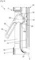
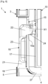
- gripping elements 18 are pivotally mounted along an axis X1 on the contour 17 of the container 10 in order to be able to pivot from a deployed position at right angles to said contour 17, as illustrated in figure 6 , to a folded position against the contour wall 17, as illustrated in figure 8 .
- the side walls 5, 6 of the base 3 each comprise on their external faces 19, 20 a cavity 21, 21'.
- the cutouts 15, 16 preferably have the shape of a slot allowing a gripping element 18 to be inserted therein in the deployed position, which allows the container 10 to be inserted into the housing 9 by passing through the front opening 8.
- the cutouts 15, 16 may be slightly flared at the free edges 5a, 6a of the side walls 5, 6 so as to facilitate the introduction of the gripping elements 18 in the deployed position.
- the gripping elements 18 protrude from the cutouts 15, 16 and are accessible from the outside of the side walls 5, 6, which allows these gripping elements 18 to be correctly grasped during the insertion of the container 10 into the housing 9 and its removal therefrom.
- the diameter of the contour 17 and/or the length of the gripping elements 18 on the container 10 are adapted according to the housing 9 and the spacing between the two walls lateral 5, 6 on the base 3.
- These gripping elements 18 can then be pivoted from the deployed position illustrated in figure 6 to the folded position shown in figure 8 , according to which said gripping elements 18 are housed in the cavities 21, 21' on the side walls 5, 6.
- the cavities 21, 21' thus form stops which prevent the gripping elements 18 from being released from the container 10 in the folded position. This makes it possible to ensure that the container 10 is held in position in the housing 9 during operation of the heating block 2.
- the gripping elements 18 have a body 22 extended by a handle 23, the body 22 and the handle substantially forming an “L”.
- the body is mounted on a pivot of axis X1 relative to the contour 17 of the container 10, as specified above.
- the bodies 22 of the gripping elements 18 bear on the lower faces 15a, 16a of the cutouts 15, 16, which allows the side walls 5, 6 to support the container 10 inserted in the housing 9.
- the shape of the body 22 makes it possible to define on it a cam 24 which bears on the lower face 15a, 16a of the cutout 15, 16.
- the lower faces 15a, 16a of the cutouts 15, 16 as well as the cam 24 thus define a lifting device 24, 15a, 16a.
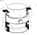
- the base 4 of the base 3 may also comprise on its upper face 25 a guide system comprising guide ramps 26a, 26b, 26c, preferably three guide ramps 26a, 26b, 26c distributed in a triangle, two of these guide ramps 26a, 26b being arranged towards the front at the level of the front opening 8 and the third guide ramp 26c being arranged near the bottom wall 7, as shown in FIG. figure 10 .
- These guide ramps 26a, 26b, 26c are particularly useful with a suitable container 10, as in the figure 1 , for which when inserting said container 10 into the housing 9, the bottom 27 of the container 10 first bears on the first two guide ramps 26a, 26b then also on the third guide ramp 26c so as to position the gripping elements 18 opposite the cutouts 15, 16 so that they do not abut against the free edges 5a, 6a of the side walls 5, 6 when inserting the container 10 into the housing 9.
- the apparatus 1 may for example comprise a locking device (not illustrated) comprising two blocking parts which are articulated on the side walls 5, 6 to be moved manually or by actuating operating members acting respectively on said blocking parts, in a first position where the blocking parts are disengaged from the cutouts 15, 16 to cause the gripping elements 18 to penetrate therein and in a second position where said blocking parts close the cutouts 15, 16 at the free edges 5a, 6a of the side walls 5, 6 to constitute stops preventing the extraction of the gripping elements 18 from said cutouts 15, 16.
- a locking device (not illustrated) comprising two blocking parts which are articulated on the side walls 5, 6 to be moved manually or by actuating operating members acting respectively on said blocking parts, in a first position where the blocking parts are disengaged from the cutouts 15, 16 to cause the gripping elements 18 to penetrate therein and in a second position where said blocking parts close the cutouts 15, 16 at the free edges 5a, 6a of the side walls 5, 6 to constitute stops preventing the extraction of the gripping elements 18 from said cutout
- the gripping elements 18 are arranged in a first position in which the gripping elements 18 are arranged in a second ... 18 could be fixed on the outline 17 of the container 10 or, on the contrary, articulated as previously in order to be able to raise the container in the housing thanks to the presence of the cams 24.
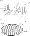
- this cooking utensil 28 can be a grill 29, illustrated in figure 11 , for grilling, but one could envisage a plate for making quiches or pizzas, or even a mold comprising a flat rigid surface on which one or more imprints are arranged.
- a cooking utensil 28 will be placed in the housing 9 and supported by the side walls 5, 6, or even by the bottom wall 7.
- the internal faces 5b, 6b of the side walls 5, 6 will comprise support elements (not illustrated) for example in the form of transverse ribs on said side walls 5, 6, said cooking utensil 28 comprising on its lateral sides two support elements 28a, 28b which will bear on these ribs when the utensil 28 is placed in the housing 9, in correspondence with said ribs.
- two opposite portions 30a, 30b of the contour 30 of the grid 29 will come to bear on the two ribs arranged at the same height on the internal faces 5b, 6b of the side walls 5, 6.
- ribs can be arranged transversely at different heights on each of the internal faces 5b, 6b of the side walls 5, 6, for example two or three ribs, or even more, so as to allow the positioning of the cooking utensil 28 at different heights inside the housing 9, in order to move said cooking utensil 28 more or less away from the lower edge 13 of the heating block 2.
- the heating block 2 will be used differently depending on whether a container 10 or a cooking utensil 28 is arranged in the housing 9 of the base 3. Indeed, the heating device 11 and the circulation device hot air from the heating block 2 are used concomitantly when a container 10 is placed in the housing 9. Whereas with a cooking utensil 28 placed in the housing 9, only the heating device 11 of the heating block 2 can be used.
- the heating block 2 is removable from the base 3.
- the heating block 2 comprises a contour 31 which comprises a first portion 31a and a second portion 31b.
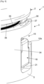
- a narrowing zone 32 is arranged on a part of the second portion 31b of the contour 31 as shown in figures 3 And 4 , which makes it possible to define a shoulder 33 between the first portion 31a and the second portion 31b.
- the first portion 31a is arranged in the lower part and the second portion 31b is arranged in the upper part when the heating block 2 is arranged upright, in the first functional configuration of the device 1.
- the base 3 has a contour 34 which incorporates the side walls 5, 6 and the bottom wall 7.
- this contour 34 of the base 3 is in a single piece, but one could provide a contour 34 in three pieces 34a, 34b, 34c constituting the two side walls 5, 6 and the bottom wall 7 of the base 3, as shown in figure 10 .
- the contour 34 of the base 3 comprises an upper edge 35 on which a lower edge 36 rests on the heating block 2 when it is normally positioned on the base 3, in the first functional configuration of the appliance 1.
- the upper edge 35 of the contour 34 comprises notches 37 and the lower edge 36 of the heating block 2 comprises lugs 38 defining a hooking device 37 , 38 .
- the lugs 38 engage respectively in the notches 37 in order to hook the heating block 2 with the base 3 in the first functional configuration of the appliance 1.
- the lugs 38 can engage in the notches 37, for example by performing a slight snap-fastening of said lugs 38 in said notches 37 when they are engaged.
- it would be possible to provide for actuating these legs 38 for example by providing a transmission mechanism (not illustrated) arranged between said legs 38 and a gripping handle 39 arranged on the upper face 40 of the heating block 2, this gripping handle 39 also allowing the handling of the heating block 2 to release it from the base 3 or place it on the latter.
- the heating block 2 can be placed in the inverted position once it has been released from the base 3, then be placed over said base 3 with a precise orientation in order to be able to accommodate the narrowing zone 32 inside the contour 34 of the base 3, until the shoulder 33 comes to bear against the upper edge 35 of said contour 34 of the base 3, which makes it possible to insert the second portion 31b of the heating block 2 in the housing 9 of the base 3.
- FIG. 12 And 13 a variant of the device 1 is illustrated, which has characteristics comparable to those presented previously with regard to the Figures 1 to 11 , the essential difference relating to the shape of the second portion 31b of the contour 31 of the heating block 2 which is smaller than the diameter of the contour 17 of the container 10, which allows when said heating block 2 is in the inverted position, that is to say in the storage configuration or in the second functional configuration, to insert said second portion 31b into the container 10 while keeping it in position in the housing 9 of the base 3.
- the heating block 2 comprises support means formed by a peripheral edge 43 which, when said heating block 2 is in the inverted position and stabilized above the base 3, makes it possible to receive the bottom 27 of the container 10, as shown in figure 13 (this also applies to the case of figures 2 And 3 ).
- the heating block 2 in the inverted position can support the container 10 by placing the bottom 27 of said container 10 near the heating device 11, then making it possible to heat said container 10 via the bottom 27 for cooking food according to a second functional configuration.
- the invention also relates to a cooking system which comprises an appliance 1 having the aforementioned characteristics and an accessory kit which comprises at least one container 10.
- the accessory kit will comprise several containers 10 which may have different contour heights 17. and/or be designed in different materials, for example transparent glass, opaque glass, stainless steel, aluminum or other materials with a coating suitable for cooking food.
- the accessory kit may also include one or more lids (not shown) adapted to the various containers so as to cover the container 10 once it is removed from the housing 9 and to be able to retain the heat in said container 10 containing the cooked food.
- This accessory kit may also include cooking utensils 28 as presented above, in a version adapted to the appliance 1.
- the gripping elements 18 may be of a different shape and the cutouts 15, 16 on the side walls 5, 6 may have a shape different from that of a slot so as to adapt them to said gripping elements 18.
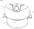
- the removable heating block 2 can be placed directly on other types of cooking containers 41 having a suitable diameter, for example a saucepan or a stewpot.
- the accessory kit can include such cooking containers 41 in addition to the container(s) 10 intended to be inserted into the housing 9 of the base 3.
- the seal 12 will preferably be implemented on the lower edge 13 of the heating block 2.
- These cooking containers 41 of the saucepan and stewpot type, or other, will allow the reception of the heating block 2 without being adapted to be placed in the housing 9 of the base 3. The user could thus place this heating block 2 on other saucepans or stewpots that he already has in his kitchen and which are adapted to receive said heating block 2.
Landscapes
- Engineering & Computer Science (AREA)
- Food Science & Technology (AREA)
- Cookers (AREA)
- Electric Stoves And Ranges (AREA)
- Baking, Grill, Roasting (AREA)
Applications Claiming Priority (2)
| Application Number | Priority Date | Filing Date | Title |
|---|---|---|---|
| FR1909531A FR3100119B1 (fr) | 2019-08-29 | 2019-08-29 | Appareil de cuisson a air chaud avec plusieurs configurations fonctionnelles |
| EP20189714.7A EP3785583B1 (de) | 2019-08-29 | 2020-08-05 | Heissluftkochgerät mit mehreren funktionseinstellungen |
Related Parent Applications (2)
| Application Number | Title | Priority Date | Filing Date |
|---|---|---|---|
| EP20189714.7A Division EP3785583B1 (de) | 2019-08-29 | 2020-08-05 | Heissluftkochgerät mit mehreren funktionseinstellungen |
| EP20189714.7A Division-Into EP3785583B1 (de) | 2019-08-29 | 2020-08-05 | Heissluftkochgerät mit mehreren funktionseinstellungen |
Publications (2)
| Publication Number | Publication Date |
|---|---|
| EP4420574A2 true EP4420574A2 (de) | 2024-08-28 |
| EP4420574A3 EP4420574A3 (de) | 2024-09-11 |
Family
ID=68211093
Family Applications (2)
| Application Number | Title | Priority Date | Filing Date |
|---|---|---|---|
| EP24189093.8A Pending EP4420574A3 (de) | 2019-08-29 | 2020-08-05 | Heissluftkochgerät mit mehreren funktionskonfigurationen |
| EP20189714.7A Active EP3785583B1 (de) | 2019-08-29 | 2020-08-05 | Heissluftkochgerät mit mehreren funktionseinstellungen |
Family Applications After (1)
| Application Number | Title | Priority Date | Filing Date |
|---|---|---|---|
| EP20189714.7A Active EP3785583B1 (de) | 2019-08-29 | 2020-08-05 | Heissluftkochgerät mit mehreren funktionseinstellungen |
Country Status (4)
| Country | Link |
|---|---|
| EP (2) | EP4420574A3 (de) |
| CN (2) | CN112438620B (de) |
| ES (1) | ES2991164T3 (de) |
| FR (1) | FR3100119B1 (de) |
Families Citing this family (5)
| Publication number | Priority date | Publication date | Assignee | Title |
|---|---|---|---|---|
| CN112932280B (zh) * | 2021-04-01 | 2025-07-11 | 宁波采臣电器有限公司 | 一种带冷风通道的上置式多功能料理锅 |
| CN112842100A (zh) * | 2021-04-01 | 2021-05-28 | 宁波采臣电器有限公司 | 一种上置式多功能空气炸锅及其加热盖 |
| CN217471753U (zh) * | 2022-01-02 | 2022-09-23 | 宁波嘉乐智能科技股份有限公司 | 一种翻转两用多功能空气炸锅 |
| CN217827583U (zh) | 2022-07-19 | 2022-11-18 | 杨敏 | 一种多功能空气炸锅 |
| USD1122667S1 (en) | 2024-10-23 | 2026-04-21 | StoreBound LLC | Cooking appliance |
Family Cites Families (11)
| Publication number | Priority date | Publication date | Assignee | Title |
|---|---|---|---|---|
| FR1485674A (fr) * | 1966-05-10 | 1967-06-23 | C C P E Circuits Chauffants Pa | Appareil électro-ménager à utilisations multiples et comportant une résistance électrique commune |
| CH562597A5 (de) * | 1972-05-04 | 1975-06-13 | Unigriversa Messeneuheiten | |
| CN201119786Y (zh) * | 2007-08-20 | 2008-09-24 | 游图明 | 一种煎烤器 |
| US8330083B2 (en) * | 2007-11-30 | 2012-12-11 | Hearthware, Inc. | Portable countertop electric oven |
| IT1390860B1 (it) * | 2008-09-29 | 2011-10-19 | De Longhi Spa | Friggitrice e procedimento di cottura |
| CN203493462U (zh) * | 2013-04-26 | 2014-03-26 | 广东四会互感器厂有限公司 | 一种电热纳米膜多功能电烤炉 |
| USD743201S1 (en) * | 2014-08-08 | 2015-11-17 | E. Mishan & Sons, Inc. | Air fryer |
| CN105686620A (zh) * | 2016-04-22 | 2016-06-22 | 周林斌 | 一种高效能烤锅 |
| FR3072265B1 (fr) * | 2017-10-16 | 2019-11-08 | Seb S.A. | Appareil electrique de cuisson comportant un support de vidange avec configuration de rangement |
| CN109589010B (zh) * | 2018-11-13 | 2024-05-14 | 宁波凯波集团有限公司 | 烹饪模式控制装置及自动设定工作模式的煎烤器 |
| CN109620014A (zh) * | 2018-12-21 | 2019-04-16 | 广东顺德金易厨电器有限公司 | 滚筒式烹饪机的工作模式选择方法及滚筒式烹饪机 |
-
2019
- 2019-08-29 FR FR1909531A patent/FR3100119B1/fr active Active
-
2020
- 2020-08-05 EP EP24189093.8A patent/EP4420574A3/de active Pending
- 2020-08-05 ES ES20189714T patent/ES2991164T3/es active Active
- 2020-08-05 EP EP20189714.7A patent/EP3785583B1/de active Active
- 2020-08-24 CN CN202010856496.8A patent/CN112438620B/zh active Active
- 2020-08-24 CN CN202510053829.6A patent/CN119632426A/zh active Pending
Also Published As
| Publication number | Publication date |
|---|---|
| EP4420574A3 (de) | 2024-09-11 |
| EP3785583A1 (de) | 2021-03-03 |
| FR3100119B1 (fr) | 2021-09-10 |
| EP3785583B1 (de) | 2024-09-04 |
| FR3100119A1 (fr) | 2021-03-05 |
| CN112438620A (zh) | 2021-03-05 |
| CN112438620B (zh) | 2025-02-11 |
| ES2991164T3 (es) | 2024-12-02 |
| CN119632426A (zh) | 2025-03-18 |
Similar Documents
| Publication | Publication Date | Title |
|---|---|---|
| EP3785583B1 (de) | Heissluftkochgerät mit mehreren funktionseinstellungen | |
| EP3785582B1 (de) | Heissluftkochgerät mit reduziertem platzbedarf in einer lagerungskonfiguration | |
| EP3721760B1 (de) | Heissluftkochgerät mit vorderer öffnung zum einsetzen und entfernen eines kochbehälters | |
| CA3037236C (fr) | Appareil de cuisson du type friteuse a air chaud | |
| FR2794014A1 (fr) | Appareil culinaire electrique multi-fonctions | |
| EP3450855A1 (de) | Abdeckelement für eine öffnung eines backhohlraums eines miniofens | |
| EP1958551A1 (de) | Koch- und Abtropfgerät für Lebensmittel in einer Flüssigkeit mit Dampfabzugs- und Abtropflöchern | |
| WO2011080425A1 (fr) | Ustensile à manipulation simplifiée | |
| FR3079600A1 (fr) | Element couvrant pour une ouverture d'une cavite de cuisson d'un mini-four | |
| EP3597086A1 (de) | Kochgerät vom typ heissluft-friteuse mit kochzubehörteilen für verschiedene speisenzubereitungen | |
| EP3785584B1 (de) | Heissluftkochgerät, das mit einer aufnahmebasis für einen kochbehälter und einer verriegelungsvorrichtung zwischen dem behälter und der basis ausgestattet ist | |
| FR2807307A1 (fr) | Systeme d'accessoires pour une rotissoire | |
| EP3912528B1 (de) | Kochgerät, das mit einem behälter mit einem abnehmbaren system zum antrieb eines rührblatts ausgestattet ist, und montageverfahren dieses systems | |
| EP3708044B1 (de) | Kit aus elementen zur montage eines behälters eines kochgeräts, wie ein heissluftfrittiergerät | |
| EP1413832A2 (de) | Kochvorrichtung für insbesondere aufgehende Teiggerichte, die einen Einschub für einen Hausbackofen darstellt | |
| WO2026068679A1 (fr) | Accessoire de cuisson pour un dispositif de cuisson | |
| CA3220114A1 (fr) | Appareil de cuisson comprenant un dispositif de collecte configure pour collecter des jus de cuisson et des condensats | |
| FR3153980A1 (fr) | Appareil de cuisson électrique pour préparations culinaires individuelles | |
| CA3247476A1 (fr) | Appareil de cuisson électrique | |
| WO2021019133A1 (fr) | Barbecue comportant une grille amovible à hauteur réglable | |
| EP3795041A1 (de) | Zubehörteil zum aufwärmen von brotscheiben auf einem kochgerät vom typ plancha oder grill | |
| WO2021245270A1 (fr) | Recipient de preparation culinaire muni d'une poignee facilitant le deversement et le raclage de la preparation culinaire | |
| FR3095933A1 (fr) | Dispositif de type grill pour cuire/griller/toaster un aliment | |
| FR2690827A3 (fr) | Grilloir à steak destiné à faire cuire des aliments, notamment pour les retourner à l'aide d'aucun instrument de cuisine. | |
| WO2012153307A1 (fr) | Dispositif de cuisson a gaz |
Legal Events
| Date | Code | Title | Description |
|---|---|---|---|
| PUAI | Public reference made under article 153(3) epc to a published international application that has entered the european phase |
Free format text: ORIGINAL CODE: 0009012 |
|
| STAA | Information on the status of an ep patent application or granted ep patent |
Free format text: STATUS: THE APPLICATION HAS BEEN PUBLISHED |
|
| PUAL | Search report despatched |
Free format text: ORIGINAL CODE: 0009013 |
|
| AC | Divisional application: reference to earlier application |
Ref document number: 3785583 Country of ref document: EP Kind code of ref document: P |
|
| AK | Designated contracting states |
Kind code of ref document: A2 Designated state(s): AL AT BE BG CH CY CZ DE DK EE ES FI FR GB GR HR HU IE IS IT LI LT LU LV MC MK MT NL NO PL PT RO RS SE SI SK SM TR |
|
| AK | Designated contracting states |
Kind code of ref document: A3 Designated state(s): AL AT BE BG CH CY CZ DE DK EE ES FI FR GB GR HR HU IE IS IT LI LT LU LV MC MK MT NL NO PL PT RO RS SE SI SK SM TR |
|
| RIC1 | Information provided on ipc code assigned before grant |
Ipc: A47J 37/06 20060101AFI20240802BHEP |
|
| STAA | Information on the status of an ep patent application or granted ep patent |
Free format text: STATUS: REQUEST FOR EXAMINATION WAS MADE |
|
| 17P | Request for examination filed |
Effective date: 20250124 |