EP4420996A2 - Élément verseur refermable pour emballages composites carton/plastique doté d'une bague d'ancrage pour la fixation sécurisée d'un couvercle à vis - Google Patents
Élément verseur refermable pour emballages composites carton/plastique doté d'une bague d'ancrage pour la fixation sécurisée d'un couvercle à vis Download PDFInfo
- Publication number
- EP4420996A2 EP4420996A2 EP24186738.1A EP24186738A EP4420996A2 EP 4420996 A2 EP4420996 A2 EP 4420996A2 EP 24186738 A EP24186738 A EP 24186738A EP 4420996 A2 EP4420996 A2 EP 4420996A2
- Authority
- EP
- European Patent Office
- Prior art keywords
- screw cap
- anchor ring
- pouring
- base element
- pouring element
- Prior art date
- Legal status (The legal status is an assumption and is not a legal conclusion. Google has not performed a legal analysis and makes no representation as to the accuracy of the status listed.)
- Pending
Links
Images






Classifications
-
- B—PERFORMING OPERATIONS; TRANSPORTING
- B65—CONVEYING; PACKING; STORING; HANDLING THIN OR FILAMENTARY MATERIAL
- B65D—CONTAINERS FOR STORAGE OR TRANSPORT OF ARTICLES OR MATERIALS, e.g. BAGS, BARRELS, BOTTLES, BOXES, CANS, CARTONS, CRATES, DRUMS, JARS, TANKS, HOPPERS, FORWARDING CONTAINERS; ACCESSORIES, CLOSURES, OR FITTINGS THEREFOR; PACKAGING ELEMENTS; PACKAGES
- B65D5/00—Rigid or semi-rigid containers of polygonal cross-section, e.g. boxes, cartons or trays, formed by folding or erecting one or more blanks made of paper
- B65D5/42—Details of containers or of foldable or erectable container blanks
- B65D5/72—Contents-dispensing means
- B65D5/74—Spouts
- B65D5/746—Spouts formed separately from the container
- B65D5/747—Spouts formed separately from the container with means for piercing or cutting the container wall or a membrane connected to said wall
- B65D5/749—Spouts formed separately from the container with means for piercing or cutting the container wall or a membrane connected to said wall a major part of the container wall or membrane being removed from the container after the opening
-
- B—PERFORMING OPERATIONS; TRANSPORTING
- B65—CONVEYING; PACKING; STORING; HANDLING THIN OR FILAMENTARY MATERIAL
- B65D—CONTAINERS FOR STORAGE OR TRANSPORT OF ARTICLES OR MATERIALS, e.g. BAGS, BARRELS, BOTTLES, BOXES, CANS, CARTONS, CRATES, DRUMS, JARS, TANKS, HOPPERS, FORWARDING CONTAINERS; ACCESSORIES, CLOSURES, OR FITTINGS THEREFOR; PACKAGING ELEMENTS; PACKAGES
- B65D41/00—Caps, e.g. crown caps or crown seals, i.e. members having parts arranged for engagement with the external periphery of a neck or wall defining a pouring opening or discharge aperture; Protective cap-like covers for closure members, e.g. decorative covers of metal foil or paper
- B65D41/32—Caps or cap-like covers with lines of weakness, tearing-strips, tags, or like opening or removal devices, e.g. to facilitate formation of pouring openings
- B65D41/34—Threaded or like caps or cap-like covers provided with tamper elements formed in, or attached to, the closure skirt
- B65D41/3442—Threaded or like caps or cap-like covers provided with tamper elements formed in, or attached to, the closure skirt with rigid bead or projections formed on the tamper element and coacting with bead or projections on the container
- B65D41/3447—Threaded or like caps or cap-like covers provided with tamper elements formed in, or attached to, the closure skirt with rigid bead or projections formed on the tamper element and coacting with bead or projections on the container the tamper element being integrally connected to the closure by means of bridges
-
- B—PERFORMING OPERATIONS; TRANSPORTING
- B65—CONVEYING; PACKING; STORING; HANDLING THIN OR FILAMENTARY MATERIAL
- B65D—CONTAINERS FOR STORAGE OR TRANSPORT OF ARTICLES OR MATERIALS, e.g. BAGS, BARRELS, BOTTLES, BOXES, CANS, CARTONS, CRATES, DRUMS, JARS, TANKS, HOPPERS, FORWARDING CONTAINERS; ACCESSORIES, CLOSURES, OR FITTINGS THEREFOR; PACKAGING ELEMENTS; PACKAGES
- B65D55/00—Accessories for container closures not otherwise provided for
- B65D55/02—Locking devices; Means for discouraging or indicating unauthorised opening or removal of closure
- B65D55/024—Closures in which a part has to be ruptured to gain access to the contents
-
- B—PERFORMING OPERATIONS; TRANSPORTING
- B65—CONVEYING; PACKING; STORING; HANDLING THIN OR FILAMENTARY MATERIAL
- B65D—CONTAINERS FOR STORAGE OR TRANSPORT OF ARTICLES OR MATERIALS, e.g. BAGS, BARRELS, BOTTLES, BOXES, CANS, CARTONS, CRATES, DRUMS, JARS, TANKS, HOPPERS, FORWARDING CONTAINERS; ACCESSORIES, CLOSURES, OR FITTINGS THEREFOR; PACKAGING ELEMENTS; PACKAGES
- B65D55/00—Accessories for container closures not otherwise provided for
- B65D55/16—Devices preventing loss of removable closure members
-
- B—PERFORMING OPERATIONS; TRANSPORTING
- B65—CONVEYING; PACKING; STORING; HANDLING THIN OR FILAMENTARY MATERIAL
- B65D—CONTAINERS FOR STORAGE OR TRANSPORT OF ARTICLES OR MATERIALS, e.g. BAGS, BARRELS, BOTTLES, BOXES, CANS, CARTONS, CRATES, DRUMS, JARS, TANKS, HOPPERS, FORWARDING CONTAINERS; ACCESSORIES, CLOSURES, OR FITTINGS THEREFOR; PACKAGING ELEMENTS; PACKAGES
- B65D2251/00—Details relating to container closures
- B65D2251/10—Details of hinged closures
- B65D2251/1008—Means for locking the closure in open position
-
- B—PERFORMING OPERATIONS; TRANSPORTING
- B65—CONVEYING; PACKING; STORING; HANDLING THIN OR FILAMENTARY MATERIAL
- B65D—CONTAINERS FOR STORAGE OR TRANSPORT OF ARTICLES OR MATERIALS, e.g. BAGS, BARRELS, BOTTLES, BOXES, CANS, CARTONS, CRATES, DRUMS, JARS, TANKS, HOPPERS, FORWARDING CONTAINERS; ACCESSORIES, CLOSURES, OR FITTINGS THEREFOR; PACKAGING ELEMENTS; PACKAGES
- B65D2401/00—Tamper-indicating means
- B65D2401/15—Tearable part of the closure
- B65D2401/30—Tamper-ring remaining connected to closure after initial removal
Definitions
- the invention relates to a resealable pouring element for cardboard/plastic composite packaging, in particular drinks packaging, with a base element having a circumferential fastening flange and an external thread, with opening means arranged inside the base element at least when the pouring element is unopened and a screw cap with an internal thread, wherein the opening means are designed such that when the composite packaging is first opened when the screw cap is unscrewed, a pouring opening is created inside the pouring element by breaking open the composite material of the packaging or a barrier layer located in the base element, wherein an anchor ring is arranged below the screw cap and is connected to it in a rotationally fixed manner, which can rotate freely radially around the base element and is connected to the base element in a tensile manner in the axial direction, and wherein, in order to securely connect the screw cap to the base element even when unscrewed, the anchor ring is articulated to the screw cap via a hinge element whose pivot axis is aligned tangentially to the outer circumference of
- a generic pouring element is known from the applicant's patent application EN 10 2006 016 113 B3 known.
- the screw cap is moved over the cutting element protruding from the pouring element and pressed (bounced) together with it onto the base element.
- a plate is molded onto the screw cap in one piece, which is connected to the screw cap via connecting bridges.
- the plate has pins on its underside that engage in corresponding recesses in the flange of the base element and are caulked from below after assembly. The connecting bridges break when opening the pouring element for the first time, so that the screw cap is then only loosely attached to the pouring element and the composite packaging.
- the US 5 215 204 A shows a closure cap for a bottle with a ring arranged under the screw cap, which is firmly connected to the screw cap via two connecting bridges.
- the ring and the bottle are designed in such a way that the ring cannot be pulled off the bottle.
- the WO 2009/048273 A2 a screw cap for a conventional bottle.
- the screw cap consists of a screw lid and a ring connected via a film hinge.
- the ring ensures that the screw cap is connected to the bottle in a tensile manner in the axial direction.
- the EP3 805 126 was only published after the filing date and also shows a pouring element with partly comparable features. However, the screw cap and anchor ring are not connected in a rotationally fixed manner by the lever-like connection, nor is the pivot axis aligned tangentially to the outer circumference of the screw cap even when unscrewed.
- the present invention is based on the task of designing and developing a resealable pouring element for cardboard/plastic composite packaging of the type mentioned at the beginning in such a way that the screw cap is connected to the pouring element even when unscrewed.
- a tensile connection is provided between the screw cap and the pouring element, in which the screw cap cannot be detached from the pouring element in the axial direction with a force of at least 10 to 30 N, which is usually necessary for the first opening of a commercially available screw cap.
- the screw cap is reliably locked in an open position with respect to the pivoting open in order to enable pouring from the composite packaging without the screw cap pivoting shut in an undesirable manner.
- a radial adjustment of the screw cap in the locked open position is particularly advantageous in order to enable pouring from any direction of the pouring element, since composite packaging is not essentially rotationally symmetrical like commercially available PET bottles or has an essentially square cross-section and can be poured equally well from any side. It is also desirable that in the locked open position there is as much free space as possible in front of the pouring opening, despite the opening means often present in the screw cap of cardboard/plastic composite packaging, which are necessary for creating a pouring opening.
- a further ring is arranged below the anchor ring, which is connected to the anchor ring via a plurality of material bridges and serves as a tamper-evident seal.
- the screw cap, the anchor ring and the further ring serving as a tamper-evident seal are manufactured as one piece.
- the ring can only be rotated to a limited extent by blocking webs that protrude inwards from the ring with locking elements arranged around the circumference of the base element, so that when the screw cap is unscrewed for the first time, it is released from the anchor ring by tearing off the material bridges and remains in its position on the base element.
- This design makes it possible to use the ring as a tamper-evident seal in a simple and elegant way, since when the screw cap is first opened, the material bridges between the ring and the anchor ring arranged above it are reliably destroyed by the rotating movement of the screw cap due to the ring's inability to rotate.
- a further embodiment of the invention provides that the base element has an outwardly projecting and essentially circumferential collar on its outside, wherein the clear inner diameter of the collar is smaller than the clear distance between the oppositely arranged webs of the ring.
- the axially tensile connection of the screw cap to the base element ensures that the screw cap does not represent a loose plastic part even when the pouring element is open and that this cannot enter the environment as a loose plastic part.
- the invention thus makes a valuable contribution to reducing environmental pollution.
- the film hinges commonly used to connect a screw cap to a base element often break after only a small number of openings and therefore cannot guarantee a secure connection of a screw cap to its base element.
- the special design of the hinge element ensures that the screw cap does not come loose from the rest of the base element even after the pouring element has been opened several times.
- the opening means comprise a cutting element arranged in the interior of the base element and at least one driver web arranged in the interior of the screw cap and connected thereto in a form-fitting or material-fitting manner, which is preferably attached to the hinge element as far as possible in the circumferential direction.
- the hinge element can be locked in the external thread of the flange in order to keep the screw cap open.
- Arranging the carrier bar as far away from the hinge element as possible in the circumferential direction ensures that the hinge elements do not get in the way when the screw cap is opened/tilted away. This enables clean opening/tilting without the hinge element and the upper edge of the pouring spout getting caught.
- the base element has on its outer side an outwardly projecting and essentially circumferential collar, wherein the clear inner diameter of the collar is smaller than the clear distance between the oppositely arranged webs of the ring.
- the at least one carrier web When pivoted open, the at least one carrier web can protrude at least partially from the inside of the screw cap. It is therefore particularly important that a sufficiently large opening angle of the screw cap can be achieved.
- the anchor ring has a slot running in the circumferential direction, which divides the anchor ring in one section into upper parts and a lower part, wherein the upper parts and the lower part are arranged at a distance from one another in the axial direction. It is advantageous if the slot is arranged in the circumferential direction in the area of the hinge element.
- the hinge element can thus be connected to the upper parts of the anchor ring in such a way that the end of the upper parts facing the hinge element is twisted after the screw cap is pivoted open.
- hinge element is arranged circumferentially centrally to the slot. This ensures that both sides of the upper parts of the anchor ring are evenly loaded when the screw cap is swung open.
- the lower end of the hinge element can protrude downwards over the lower end of the upper parts of the anchor ring in the direction of the fastening flange.
- the hinge element folds over with its lower end in the direction of the slot, so that at an opening angle of 120° to 150° the screw cap is locked in its open position with respect to its swung open. In this state the screw cap can no longer swing back without the application of force from the outside. This has the great advantage that the screw cap does not automatically swing back when pouring and does not come into contact with the product during the pouring process.
- the hinge element can be designed with a greater or equal wall thickness than the rest of the screw cap, but also with a smaller wall thickness.
- the screw cap can be designed to be freely radially rotatable in its locked open position. This has the great advantage that the screw cap can be rotated into a position desired by the user. In the locked position, a slight force must still be applied from the outside to enable rotation, since fixing the screw cap in relation to its opening creates increased frictional resistance between the hinge element and the base element. However, the increased frictional resistance is also desired so that the screw cap does not easily move in the direction of the pouring stream when pouring, caused by the force of gravity.
- a further teaching of the invention provides that the hinge element is arranged above the lower third of the base element with respect to its pivot axis in the unopened state.
- the hinge element By arranging the hinge element above the lower third, it is ensured that the screw cap can achieve an opening position with an opening angle of 120° to 150° before the screw cap hits the composite packaging. Since composite packaging typically does not have a bottle neck like PET bottles, the swiveling movement of the screw cap is significantly more limited than with PET bottles. In order to still achieve a sufficiently large opening angle for a pleasant pouring process, it is desirable to arrange the hinge element as high up as possible.
- the base element has on its outer side an outwardly projecting and substantially circumferential collar.
- a further embodiment according to the invention provides that the collar with its outer peripheral surface in the upper region of the anchor ring touches the inner surface of the anchor ring.
- the anchor ring By providing a substantially circumferential web at the lower end of the anchor ring, which is directed towards the base element and is arranged below the collar, the anchor ring is reliably prevented from being pulled off via the collar.
- At least either the collar or the web can also be interrupted at one or more points, provided that it is ensured that the anchor ring with its web directed towards the base element cannot slip over the collar provided on the base element.
- the collar is arranged in the axial direction in the upper region of the anchor ring in the unopened state, so that when the screw cap is unscrewed, the hinge element can move in the axial direction until the web comes into contact with the collar.
- the anchor ring including the hinge element can cover as much distance upwards as possible when the screw cap is unscrewed and swung open, so that the swivel axis of the hinge element is moved upwards.
- a swivel axis arranged as high as possible is desirable in order to enable the screw cap to open at as large an angle as possible for comfortable pouring, despite the lack of a bottle neck on composite packaging.
- the pivot axis of the hinge element is arranged in the axial direction in the upper half of the base element when the screw cap is pivoted away, particularly preferably in the upper third of the base element.
- ribs are provided on the base element below the collar, which protrude outwards in the direction of the anchor ring and extend perpendicular to the fastening flange. These ribs ensure that the anchor ring always has a certain distance from the base element in the radial direction. As a result, the anchor ring is centered with respect to the base element in every state.
- the fastening flange of the pouring element can be connected to the inside of the composite packaging.
- a corresponding composite packaging has a material recess at the location of the later pouring opening.
- the pouring element is guided through the interior of the composite packaging, positioned in the area of the material recess and then connected to the inside of the composite packaging.
- the base element is closed on the packaging side in the unopened state, so that the product in the composite packaging cannot flow into the pouring element in the unopened state.
- the opening means comprise an opening element which is arranged inside the base element in the unopened state and is integrally connected to it, and at least one force transmission element which is arranged inside the screw cap and is integrally connected to it.
- the opening element is positively connected to the at least one force transmission element and is separated from the base element at predetermined breaking points when the pouring element is opened for the first time, triggered by the rotation of the at least one force transmission element, so that there is no longer a material connection between the base element and the opening element. From this point on, the opening element is only positively connected to the at least one force transmission element, so that it cannot get into the composite packaging located under the pouring element.
- the opening element can protrude at least partially from the inside of the screw cap when it is swung open.
- Corresponding opening means are already known from the JP5857668B2 known.
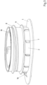
- the drawing shows a preferred embodiment of a pouring element according to the invention in order to illustrate its functionality when opening a composite package.
- Fig.1 a pouring element according to the invention without composite packaging is shown in perspective view.
- the pouring element has a base element 2 with a circumferential fastening flange 1 (which in Fig.1 is not visible) and a screw cap 3, which is used for the initial opening and for resealing a composite package (not shown).
- an anchor ring 4 is arranged which is connected to it in a rotationally fixed manner in order to reliably prevent the screw cap 3 from being removed from the base element 2 or a composite package provided with it.
- the screw cap 3 and the anchor ring 4 are connected to one another in an articulated manner via a hinge element 5, the pivot axis of which is aligned tangentially to the outer circumference of the screw cap 3.
- the anchor ring 4 has a slot 6 running in the circumferential direction, which divides the anchor ring 4 in one section into upper parts 4A and a lower part 4B, wherein the upper parts 4A and the lower part 4B are arranged at a distance from one another in the axial direction.
- the hinge element 5 can be designed with a larger, equal or smaller wall thickness compared to the rest of the screw cap 2.
- the slot 6 is arranged in the circumferential direction centrally to the hinge element 5.
- the hinge element 5 is connected to the upper parts 4A of the anchor ring 4 and is arranged with respect to its pivot axis in the unopened state above the lower third of the base element 2.
- the lower end of the hinge element 5, in the unopened state of the pouring element projects downwards over the lower end of the upper parts 4A of the anchor ring 4 in the direction of the fastening flange 1.
- ribs 7 are provided on the lower area of the base element 2 which project outwards in the direction of the anchor ring 4 and extend perpendicularly to the fastening flange 1.
- Fig.3 shows the base element 2 of the Fig.1 It can be seen that the base element 2 has an external thread 8, by means of which the pouring element Fig.3 A screw cap 3 (not shown) can be screwed onto the base element 2.
- the base element 2 also has an outwardly projecting and radially encircling collar 9 on its outside above the ribs 7.
- a cutting element 10 can be seen inside the base element 2, which creates a pouring opening within the pouring element when the composite package is first opened by screwing on the screw cap 3.
- Fig.4 The pouring element is now shown in vertical section in the unopened state.
- the collar 9 touches the inner surface of the anchor ring 4 with its outer peripheral surface in the upper region of the anchor ring 4.
- the anchor ring 4 has at its lower end a radially circumferential web 11 directed towards the base element 2, which is arranged below the collar 9 provided on the base element 2. This prevents the anchor ring 4 from being pulled off beyond the collar 9.
- the collar 9 is arranged in the upper region of the anchor ring 4, so that when the screw cap 3 is screwed on, the movement of the anchor ring 4 and thus also that of the hinge element 5 in an axial upward direction is possible until the web 11 comes into contact with the collar 9.
- an opening means can be seen, consisting of the cutting element 10 arranged inside the base element 2 and driver webs 12 arranged inside the screw cap 3, which are materially connected to the latter.
- the cutting element 10 which has an external thread 13
- the driver webs 12 are conveyed in the direction of the composite package by means of the driver webs 12 and an internal thread 14 formed on the base element 2 by screwing on the screw cap 3, so that a pouring opening is created within the pouring element.
- the driver webs 12 protrude downwards in comparison to the outer peripheral surface of the screw cap 3, so that they protrude from the interior of the screw cap 3 when pivoted open.
- Fig. 5 to 8 finally illustrate the function of the pouring element according to the invention during the opening process of the screw cap 3.
- Fig.5 the pouring element is shown at the beginning of the screwing process of the screw cap 3.
- the anchor ring 4 can rotate freely radially is connected to the base element 2 so that the anchor ring 4 moves with the rotational movement of the screw cap 3.
- Fig.6 The pouring element is shown with the screw cap 3 already screwed on but still closed. On the left side of the Fig.6 the pouring element is shown in a side view, while the right side of the Fig.6 represents a vertical section.
- the anchor ring 4 and the hinge element 5, along with it, have also moved upwards due to the upward movement of the screw cap 3.
- the collar 9 provided on the base element 2 and the web 11 arranged on the anchor ring touch each other.
- the slot 6 has increased in size at least in the middle in the axial direction due to the upward movement of the screw cap 3, so that the pivot axis of the hinge element 5 has moved further upwards in the axial direction.
- Fig.7 the pouring element is shown in an open state and with a swivelled screw cap 3 with a composite package.
- the anchor ring 4 cannot slip over the collar 9, so that despite its ability to rotate with respect to the base element 2, it is connected to the base element 2 in a tensile manner in the axial direction.
- the anchor ring 4 and thus also the screw cap 3 are reliably prevented from being pulled off.
- Fig.7 that by pivoting the screw cap 3, the upper parts 4A of the anchor ring 4 at one end, which form a connection to the hinge element 5, twist but do not break off.
- the hinge element 5 rotates by pivoting the screw cap 3 in the direction of the slot 6 until it is in the slot as shown in Fig.8 shown so that it is locked in its open position at an opening angle of 120° to 150° with respect to its pivoting.
- the screw cap 3 can still rotate freely radially in its locked open position, although due to an increased Due to frictional resistance, a certain force must be applied from the outside to enable rotation.
- a band 15 serving as an authenticity seal is attached to the anchor ring 4, one end of which is firmly connected to the anchor ring 4 and the other end of which is connected to the anchor ring 4 by means of a predetermined breaking point in such a way that the predetermined breaking point is broken open by a mandrel element 16 arranged on the fastening flange 1 when the screw cap 3 is screwed on for the first time.
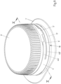
- Fig.9 shows a further embodiment of a pouring element according to the invention without composite packaging in perspective view.
- This pouring element has, as in the first embodiment according to Fig.1 , a circumferential fastening flange 1' and a screw cap 3'.
- Below the screw cap 3' there is, as in the first embodiment, an anchor ring 4' connected to it in a rotationally fixed manner for connecting the screw cap 3' to the (in Fig.9 not visible) base element.
- the design of the screw cap 3' and the anchor ring 4' located underneath correspond exactly to the first embodiment from Fig.1 .
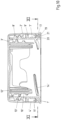
- Fig.10 corresponds essentially to the vertical section according to Fig.4 , so that reference can be made to the description of the screw cap 3', the anchor ring 4' and the cutting element 10'.
- the (further) ring 17 can be clearly seen, which is designed as an authenticity seal.
- the ring 17 has a plurality of webs 19 distributed over the circumference and projecting inwards, which come into contact with corresponding locking elements 20 extending from the base element 2' when the screw cap 3' is first screwed on and block further rotation of the ring 17, as will be described in more detail below.
- Fig. 11 the pouring element is made of Fig.9 in horizontal section along the line XI-XI Fig.10 shown.
- the base element 2' has a plurality of outwardly projecting locking elements 20, 20A and 20B, which interact with the aforementioned webs 19, 19A and 19B in such a way that the ring 17 blocks when unscrewed, so that the material bridges 18 arranged above it break off and no longer hinder the further rotation of the anchor ring 4'.
- the base element 2' has an outwardly protruding and essentially circumferential collar 21 on its outside, the clear inner diameter of the collar 21 being smaller than the clear distance between the oppositely arranged webs 19 of the ring 17.
- the ring 17 is reliably prevented from moving from its lower position 17 on the base element 2' even when the screw cap is screwed on. This ensures that the ring 17 cannot enter the environment as a "loose plastic part".
- FIG. 13 A further embodiment of a pouring element according to the invention is shown, in which the fastening flange 1" of the pouring element is connected with its upper side to the inside of a composite package P.
- a corresponding composite package P has a material recess at the location of the later pouring opening.
- the Pouring element is guided through the interior of the composite packaging P, positioned in the area of the material recess and then connected to the inside of the composite packaging P, for example by means of ultrasound.
- the base element 2" is closed on the inside of the packaging side in the unopened state, so that the product in the composite packaging P cannot flow into the pouring element in the unopened state.
- the opening means of this pouring element comprise an opening element 22 which, in the unopened state, is arranged inside the base element 2" and is integrally connected to it, and two force transmission elements 23 which are arranged inside the screw cap 3" and are integrally connected to it.
- the force transmission elements 23 each comprise a radially inwardly projecting hook 24 at their downwardly directed end.
- Recesses 25 are provided at the corresponding points on the opening element 22, into which the hooks 24 of the force transmission elements 23 engage in the assembled state, so that a positive connection is created.
- a radially circumferential predetermined breaking point 26 is provided in the section in which the base element 2" and the opening element 22 are integrally connected to one another, so that the integral connection can be easily severed when the screw cap 3" is screwed on. It is clearly visible that the opening element 22 protrudes downwards in comparison to the outer peripheral surface of the screw cap 3", so that it protrudes from the interior of the screw cap 3" when pivoted open.
Landscapes
- Engineering & Computer Science (AREA)
- Mechanical Engineering (AREA)
- Closures For Containers (AREA)
- Cartons (AREA)
Applications Claiming Priority (5)
| Application Number | Priority Date | Filing Date | Title |
|---|---|---|---|
| DE102019132541.2A DE102019132541C5 (de) | 2019-11-29 | 2019-11-29 | Wiederverschließbares Ausgießelement für Karton/Kunststoff-Verbundpackungen mit einem Ankerring zur sicheren Anbindung eines Schraubdeckels |
| DE102020106661.9A DE102020106661A1 (de) | 2020-03-11 | 2020-03-11 | Wiederverschließbares Ausgießelement für Karton/Kunststoff-Verbundpackungen mit einem Ankerring zur sicheren Anbindung eines Schraubdeckels |
| EP20812302.6A EP4065483B9 (fr) | 2019-11-29 | 2020-11-25 | Élément verseur refermable pour emballage composite carton/plastique doté d'une bague d'ancrage pour fixer solidement un bouchon à vis |
| EP23199205.8A EP4282774A3 (fr) | 2019-11-29 | 2020-11-25 | Élément verseur refermable pour emballage composite carton/plastique doté d'une bague d'ancrage pour fixer solidement un bouchon à vis |
| PCT/EP2020/083309 WO2021105176A1 (fr) | 2019-11-29 | 2020-11-25 | Élément verseur refermable pour emballage composite carton/plastique doté d'une bague d'ancrage pour fixer solidement un bouchon à vis |
Related Parent Applications (2)
| Application Number | Title | Priority Date | Filing Date |
|---|---|---|---|
| EP20812302.6A Division EP4065483B9 (fr) | 2019-11-29 | 2020-11-25 | Élément verseur refermable pour emballage composite carton/plastique doté d'une bague d'ancrage pour fixer solidement un bouchon à vis |
| EP23199205.8A Division EP4282774A3 (fr) | 2019-11-29 | 2020-11-25 | Élément verseur refermable pour emballage composite carton/plastique doté d'une bague d'ancrage pour fixer solidement un bouchon à vis |
Publications (2)
| Publication Number | Publication Date |
|---|---|
| EP4420996A2 true EP4420996A2 (fr) | 2024-08-28 |
| EP4420996A3 EP4420996A3 (fr) | 2024-11-13 |
Family
ID=73598112
Family Applications (3)
| Application Number | Title | Priority Date | Filing Date |
|---|---|---|---|
| EP20812302.6A Active EP4065483B9 (fr) | 2019-11-29 | 2020-11-25 | Élément verseur refermable pour emballage composite carton/plastique doté d'une bague d'ancrage pour fixer solidement un bouchon à vis |
| EP24186738.1A Pending EP4420996A3 (fr) | 2019-11-29 | 2020-11-25 | Élément verseur refermable pour emballages composites carton/plastique doté d'une bague d'ancrage pour la fixation sécurisée d'un couvercle à vis |
| EP23199205.8A Pending EP4282774A3 (fr) | 2019-11-29 | 2020-11-25 | Élément verseur refermable pour emballage composite carton/plastique doté d'une bague d'ancrage pour fixer solidement un bouchon à vis |
Family Applications Before (1)
| Application Number | Title | Priority Date | Filing Date |
|---|---|---|---|
| EP20812302.6A Active EP4065483B9 (fr) | 2019-11-29 | 2020-11-25 | Élément verseur refermable pour emballage composite carton/plastique doté d'une bague d'ancrage pour fixer solidement un bouchon à vis |
Family Applications After (1)
| Application Number | Title | Priority Date | Filing Date |
|---|---|---|---|
| EP23199205.8A Pending EP4282774A3 (fr) | 2019-11-29 | 2020-11-25 | Élément verseur refermable pour emballage composite carton/plastique doté d'une bague d'ancrage pour fixer solidement un bouchon à vis |
Country Status (10)
| Country | Link |
|---|---|
| US (1) | US20230025075A1 (fr) |
| EP (3) | EP4065483B9 (fr) |
| JP (1) | JP7775193B2 (fr) |
| CN (1) | CN114746343A (fr) |
| BR (1) | BR112022010291A2 (fr) |
| ES (1) | ES2964001T3 (fr) |
| MX (1) | MX2022006055A (fr) |
| PL (1) | PL4065483T3 (fr) |
| SA (1) | SA522432761B1 (fr) |
| WO (1) | WO2021105176A1 (fr) |
Families Citing this family (10)
| Publication number | Priority date | Publication date | Assignee | Title |
|---|---|---|---|---|
| WO2020212426A1 (fr) * | 2019-04-15 | 2020-10-22 | Alpla Werke Alwin Lehner Gmbh & Co. Kg | Fermeture de récipient |
| DK3854716T3 (da) | 2020-01-27 | 2025-09-08 | Elopak Asa | Lukkeanordning til en papir- eller papbaseret emballage |
| MX2023003906A (es) | 2020-10-05 | 2023-04-24 | Tetra Laval Holdings & Finance | Ensamble de cierre para un envase y envase que tiene un ensamble de cierre. |
| US12351373B2 (en) * | 2021-05-12 | 2025-07-08 | Paul Bradley Forrest | Releasable container cap |
| DE102021125520A1 (de) * | 2021-10-01 | 2023-04-06 | Bericap Holding Gmbh | Verschlussvorrichtung mit Stützring |
| EP4206084B1 (fr) * | 2021-12-30 | 2024-08-07 | Tetra Laval Holdings & Finance S.A. | Col et capuchon pour emballage alimentaire |
| DE102022118177B9 (de) * | 2022-07-20 | 2023-09-07 | Sig Combibloc Services Ag | Wiederverschließbares Ausgießelement für eine Karton/Kunststoff-Verbundpackung mit einer daran angebundenen Schraubkappe und Verfahren zur Montage einer Schraubkappe |
| US20240101324A1 (en) * | 2022-09-22 | 2024-03-28 | Cheer Pack North America | Container and Cap Assembly |
| DE102022133762B4 (de) * | 2022-12-16 | 2024-11-14 | Sig Services Ag | Verfahren zur Herstellung eines Ausgießelementes und Ausgießelement |
| DE102022133763B4 (de) * | 2022-12-16 | 2024-11-14 | Sig Services Ag | Verfahren zur Herstellung eines Ausgießelementes und Ausgießelement |
Citations (6)
| Publication number | Priority date | Publication date | Assignee | Title |
|---|---|---|---|---|
| US5215204A (en) | 1992-03-09 | 1993-06-01 | Creative Packaging Corp. | Tamper evident closure with hinged band |
| EP1124734B1 (fr) | 1998-10-29 | 2002-07-17 | Crown Cork & Seal Technologies Corporation | Bouchon a vis avec bande de garantie |
| DE102006016113B3 (de) | 2006-04-04 | 2007-08-23 | Sig Technology Ag | Wiederverschließbares Ausgießelement für Karton/Kunststoff-Verbundpackungen |
| WO2009048273A2 (fr) | 2007-10-10 | 2009-04-16 | Best Easy Cap Co., Ltd. | Contenant pourvu d'un bouchon anti-perte et anti-rotation à vide |
| JP5857668B2 (ja) | 2011-11-21 | 2016-02-10 | 凸版印刷株式会社 | 容器用口栓 |
| EP3805126A1 (fr) | 2019-09-30 | 2021-04-14 | Tetra Laval Holdings & Finance S.A. | Ensemble de fermeture pour un récipient et récipient doté d'un ensemble de fermeture |
Family Cites Families (44)
| Publication number | Priority date | Publication date | Assignee | Title |
|---|---|---|---|---|
| JPS5857668B2 (ja) | 1975-07-14 | 1983-12-21 | 川崎重工業株式会社 | 吸収冷凍機の吸収液結晶防止装置 |
| EP0057797B1 (fr) * | 1981-02-03 | 1986-06-25 | Imperial Chemical Industries Plc | Procédé pour l'extraction de métaux et agents d'extraction pour métaux |
| US4713207A (en) * | 1986-07-07 | 1987-12-15 | Container Corporation Of America | Manufacturing method for thermoplastic container with integral lifting ring |
| JPS642727U (fr) * | 1987-06-24 | 1989-01-10 | ||
| EA006671B1 (ru) | 2002-06-20 | 2006-02-24 | Сиг Текнолоджи Лтд. | Самовскрывающее укупорочное устройство для композитных упаковок или для горловин упаковок или бутылок, закрытых плёночным материалом |
| DE10231063A1 (de) * | 2002-07-10 | 2004-01-29 | Sig Technology Ltd. | Verfahren zum Applizieren eines wiederverschließbaren Ausgießelements an einen Behälter und danach hergestellter Behälter |
| WO2005044538A1 (fr) * | 2003-11-05 | 2005-05-19 | Sig Technology Ltd. | Element plastique etanche au gaz et en forme de piece moulee par injection, et son procede de production |
| EP1533240B1 (fr) | 2003-11-18 | 2007-01-17 | Tetra Laval Holdings & Finance SA | Dispositif d'ouverture refermable pour conditionnements en feuille scellé de produits alimentaires versables |
| US7841484B2 (en) * | 2004-09-30 | 2010-11-30 | Tetra Laval Holdings & Finance S.A. | Capped container |
| US8505760B2 (en) * | 2004-11-15 | 2013-08-13 | Sig Technology Ltd. | Flat self-opening closure for composite packagings or for container nozzles or bottle necks to be closed by film material |
| DE102005010547B4 (de) * | 2005-03-04 | 2010-08-26 | Sig Technology Ag | Ausgießelement für eine Packung zur Aufnahme fließfähiger Produkte und Verfahren zur Herstellung einer solchen Packung |
| WO2007006163A1 (fr) * | 2005-07-08 | 2007-01-18 | Sig Technology Ltd. | Dispositif de coulee etanche a l'oxygene comprenant une tubulure et une bride, destine a des emballages de carton composites |
| DE102006015524B3 (de) * | 2006-03-31 | 2007-08-02 | Sig Technology Ag | Wiederverschließbares Ausgießelement für in Karton/Kunststoff-Verbundpackungen abgefüllte flüssige Lebensmittel |
| DE102006015525B3 (de) * | 2006-03-31 | 2007-08-02 | Sig Technology Ag | Wiederverschließbares Ausgießelement für in Karton/Kunststoff-Verbundpackungen abgefüllte flüssige Lebensmittel und Verfahren zu seiner Montage |
| US7621413B2 (en) * | 2006-06-09 | 2009-11-24 | Seaquist Closures Foreign, Inc. | Closure system with orientation and removal capability |
| KR100757795B1 (ko) * | 2006-06-21 | 2007-09-11 | 채동석 | 마개 및 이 마개가 구비된 용기 |
| EP1953091A1 (fr) * | 2007-01-31 | 2008-08-06 | Obrist Closures Switzerland GmbH | Capuchon de fermeture anti-sabotage, conteneur et combinaison correspondante |
| US20110297682A1 (en) * | 2007-06-22 | 2011-12-08 | Si Joong Kwon | Container with anti-loss and anti-idle-rotation cap |
| ATE513760T1 (de) * | 2007-10-19 | 2011-07-15 | Sika Technology Ag | Verschluss |
| DE102007057863A1 (de) * | 2007-11-29 | 2009-06-04 | Sig Technology Ag | Selbstöffnendes und wiederverschließbares Ausgießelement aus Kunststoff zur Applikation auf einer Packung für Flüssigkeiten |
| JP5574582B2 (ja) * | 2008-07-08 | 2014-08-20 | 日本クロージャー株式会社 | 合成樹脂製容器蓋 |
| RU2478542C2 (ru) * | 2008-07-08 | 2013-04-10 | Джапан Краун Корк Ко., Лтд. | Выполненная из синтетической смолы крышка контейнера |
| CA132982S (en) * | 2009-05-28 | 2010-08-17 | Sig Technology Ag | Pouring spout |
| ES2385859T3 (es) | 2009-08-17 | 2012-08-01 | Tetra Laval Holdings & Finance Sa | Material de envasado de lámina de múltiples capas para producir envases de productos de alimentación vertibles |
| CN102652098B (zh) * | 2010-01-25 | 2014-10-29 | 权始重 | 防止瓶盖丢失或空转的容器 |
| WO2011093597A2 (fr) * | 2010-01-28 | 2011-08-04 | 주식회사 그린캡 | Bouchon pour contenant d'emballage |
| JP2013518002A (ja) * | 2010-01-28 | 2013-05-20 | グリーンキャップ カンパニー リミテッド | 包装容器栓 |
| DE102010028518A1 (de) * | 2010-05-04 | 2011-11-10 | Robert Bosch Gmbh | Verschlussvorrichtung |
| DE102010048415A1 (de) * | 2010-10-15 | 2012-04-19 | Sig Technology Ag | Wiederverschließbares Ausgießelement mit Barrierefolie und Stützwand |
| WO2012085153A2 (fr) | 2010-12-21 | 2012-06-28 | Capartis Ag | Verseur, procédé pour produire un verseur et fermeture de contenant pourvu d'un tel verseur |
| JP2012066879A (ja) * | 2011-10-10 | 2012-04-05 | Nihon Tetra Pak Kk | 注出口栓及び注出口栓の製造法 |
| CH708742A1 (de) * | 2013-10-25 | 2015-04-30 | Terxo Ag | Selbstöffnerverschluss zum Öffnen und Wiederverschliessen einer Verpackung. |
| US9776779B2 (en) * | 2014-03-10 | 2017-10-03 | Phillip John Campbell | Closure with spring loaded tether docking |
| USD844430S1 (en) * | 2016-04-04 | 2019-04-02 | Sig Technology Ag | Beverage carton |
| PL3464090T3 (pl) | 2016-05-31 | 2020-11-02 | Sig Technology Ag | Element do wylewania dla opakowania laminatowego oraz opakowanie laminatowe z elementem do wylewania |
| DE102016110047B3 (de) * | 2016-05-31 | 2017-05-04 | Sig Technology Ag | Ausgießelement für eine Verbundpackung sowie Verbundpackung mit einem Ausgießelement |
| US10676261B2 (en) | 2017-09-07 | 2020-06-09 | Silgan White Cap LLC | Closure assembly |
| US20190375555A1 (en) * | 2018-06-12 | 2019-12-12 | Closure Systems International Inc. | Tethered Bridge Closure |
| PL3826930T3 (pl) * | 2018-07-23 | 2024-03-11 | Sig Services Ag | Opakowanie kompozytowe z elementem do nalewania i eliptycznym, zakrytym otworem |
| ES2974521T3 (es) * | 2018-11-16 | 2024-06-27 | Bericap Holding Gmbh | Combinación de un cuello de recipiente y cierre imperdible con ángulo de apertura estabilizado |
| CN113853343B (zh) | 2019-04-05 | 2024-06-14 | 耐普罗公司 | 栓系盖和喷口 |
| US11697534B2 (en) * | 2019-07-22 | 2023-07-11 | Sacmi Cooperativa Meccanici Imola Societa' Cooperativa | Cap for a container, combination of a cap and a neck of the container and its production method |
| DE102019132541C5 (de) * | 2019-11-29 | 2026-03-19 | Sig Services Ag | Wiederverschließbares Ausgießelement für Karton/Kunststoff-Verbundpackungen mit einem Ankerring zur sicheren Anbindung eines Schraubdeckels |
| DE102019132538B4 (de) * | 2019-11-29 | 2022-08-11 | Sig Technology Ag | Wiederverschließbares Ausgießelement für Karton/Kunststoff-Verbundpackungen mit einem Originalitätssiegel zur Indikation der Erstöffnung |
-
2020
- 2020-11-25 ES ES20812302T patent/ES2964001T3/es active Active
- 2020-11-25 CN CN202080083146.0A patent/CN114746343A/zh active Pending
- 2020-11-25 MX MX2022006055A patent/MX2022006055A/es unknown
- 2020-11-25 JP JP2022531400A patent/JP7775193B2/ja active Active
- 2020-11-25 EP EP20812302.6A patent/EP4065483B9/fr active Active
- 2020-11-25 WO PCT/EP2020/083309 patent/WO2021105176A1/fr not_active Ceased
- 2020-11-25 EP EP24186738.1A patent/EP4420996A3/fr active Pending
- 2020-11-25 PL PL20812302.6T patent/PL4065483T3/pl unknown
- 2020-11-25 EP EP23199205.8A patent/EP4282774A3/fr active Pending
- 2020-11-25 US US17/780,904 patent/US20230025075A1/en active Pending
- 2020-11-25 BR BR112022010291A patent/BR112022010291A2/pt unknown
-
2022
- 2022-05-29 SA SA522432761A patent/SA522432761B1/ar unknown
Patent Citations (6)
| Publication number | Priority date | Publication date | Assignee | Title |
|---|---|---|---|---|
| US5215204A (en) | 1992-03-09 | 1993-06-01 | Creative Packaging Corp. | Tamper evident closure with hinged band |
| EP1124734B1 (fr) | 1998-10-29 | 2002-07-17 | Crown Cork & Seal Technologies Corporation | Bouchon a vis avec bande de garantie |
| DE102006016113B3 (de) | 2006-04-04 | 2007-08-23 | Sig Technology Ag | Wiederverschließbares Ausgießelement für Karton/Kunststoff-Verbundpackungen |
| WO2009048273A2 (fr) | 2007-10-10 | 2009-04-16 | Best Easy Cap Co., Ltd. | Contenant pourvu d'un bouchon anti-perte et anti-rotation à vide |
| JP5857668B2 (ja) | 2011-11-21 | 2016-02-10 | 凸版印刷株式会社 | 容器用口栓 |
| EP3805126A1 (fr) | 2019-09-30 | 2021-04-14 | Tetra Laval Holdings & Finance S.A. | Ensemble de fermeture pour un récipient et récipient doté d'un ensemble de fermeture |
Also Published As
| Publication number | Publication date |
|---|---|
| EP4420996A3 (fr) | 2024-11-13 |
| WO2021105176A1 (fr) | 2021-06-03 |
| EP4065483B9 (fr) | 2023-12-27 |
| EP4282774A2 (fr) | 2023-11-29 |
| EP4065483B1 (fr) | 2023-09-27 |
| JP2023507896A (ja) | 2023-02-28 |
| MX2022006055A (es) | 2022-06-24 |
| US20230025075A1 (en) | 2023-01-26 |
| EP4065483C0 (fr) | 2023-09-27 |
| EP4065483A1 (fr) | 2022-10-05 |
| BR112022010291A2 (pt) | 2022-08-16 |
| JP7775193B2 (ja) | 2025-11-25 |
| PL4065483T3 (pl) | 2024-02-12 |
| EP4282774A3 (fr) | 2024-03-06 |
| SA522432761B1 (ar) | 2023-10-11 |
| CN114746343A (zh) | 2022-07-12 |
| ES2964001T3 (es) | 2024-04-03 |
Similar Documents
| Publication | Publication Date | Title |
|---|---|---|
| EP4065483B9 (fr) | Élément verseur refermable pour emballage composite carton/plastique doté d'une bague d'ancrage pour fixer solidement un bouchon à vis | |
| DE202019106993U1 (de) | Wiederverschließbares Ausgießelement für Karton/Kunststoff-Verbundpackungen mit einem Ankerring zur sicheren Anbindung eines Schraubdeckels | |
| EP4403486B1 (fr) | Bouchon imperdable présentant un angle d'ouverture stabilisé | |
| DE102019132541B3 (de) | Wiederverschließbares Ausgießelement für Karton/Kunststoff-Verbundpackungen mit einem Ankerring zur sicheren Anbindung eines Schraubdeckels | |
| DE602004012149T2 (de) | Verschluss mit originalitätssicherung | |
| EP4065482B1 (fr) | Élément verseur refermable pour emballage composite carton-lastique avec un joint d'inviolabilité pour indiquer si l'emballage a déjà été ouvert | |
| DE202021103289U1 (de) | Verschluss für einen Behälter mit besser kontrollierter Erstöffnung und verschiedene Anwendungsfälle dafür | |
| WO2021018772A1 (fr) | Bouchon captif ayant un angle d'ouverture stabilisé | |
| DE3422547A1 (de) | Manipuliersichere verschlusskappe fuer behaelter | |
| WO2006050624A1 (fr) | Element de fermeture plat a ouverture automatique pour emballages composites ou pour tubulures de recipient ou de bouteille a refermer par un film de matiere | |
| WO2022253752A1 (fr) | Fermeture pour un récipient avec une indication améliorée du fait que la fermeture a déjà été ouverte, et différentes applications de ladite fermeture | |
| EP4294735B1 (fr) | Dispositif de fermeture à bague support | |
| CH667249A5 (de) | Verschluss aus kunststoff mit garantieband. | |
| DE102020106661A1 (de) | Wiederverschließbares Ausgießelement für Karton/Kunststoff-Verbundpackungen mit einem Ankerring zur sicheren Anbindung eines Schraubdeckels | |
| EP4251529B1 (fr) | Fermeture de récipient | |
| DE102020131241A1 (de) | Unverlierbarer Kunststoffverschluss mit Ausgießeinsatz | |
| EP1339615A1 (fr) | Capuchon filete pourvu d'une bande de garantie | |
| DE102021128143B3 (de) | Verschluss für einen Behälter, insbesondere für eine Karton/Kunststoff-Verbundverpackung | |
| DE102023107877A1 (de) | Ressourcenschonende Verschlusseinrichtung | |
| EP4025516B1 (fr) | Fermeture de contenant | |
| DE102021128146B3 (de) | Verschluss für einen Behälter, insbesondere für eine Karton/Kunststoff-Verbundverpackung | |
| EP2214976B1 (fr) | Bouchon à vis à fermeture sécurisée | |
| DE19947388B4 (de) | Behältnis zur Aufnahme eines Füllgutes mit einem Drehverschluss | |
| EP1547930A1 (fr) | Dispositif pour détacher entièrement des parties en plastique des fermetures | |
| DE20120965U1 (de) | Originalitätsverschluss |
Legal Events
| Date | Code | Title | Description |
|---|---|---|---|
| PUAI | Public reference made under article 153(3) epc to a published international application that has entered the european phase |
Free format text: ORIGINAL CODE: 0009012 |
|
| STAA | Information on the status of an ep patent application or granted ep patent |
Free format text: STATUS: THE APPLICATION HAS BEEN PUBLISHED |
|
| AC | Divisional application: reference to earlier application |
Ref document number: 4065483 Country of ref document: EP Kind code of ref document: P Ref document number: 4282774 Country of ref document: EP Kind code of ref document: P |
|
| AK | Designated contracting states |
Kind code of ref document: A2 Designated state(s): AL AT BE BG CH CY CZ DE DK EE ES FI FR GB GR HR HU IE IS IT LI LT LU LV MC MK MT NL NO PL PT RO RS SE SI SK SM TR |
|
| REG | Reference to a national code |
Ref country code: DE Ref legal event code: R079 Free format text: PREVIOUS MAIN CLASS: B65D0055160000 Ipc: B65D0005740000 |
|
| PUAL | Search report despatched |
Free format text: ORIGINAL CODE: 0009013 |
|
| AK | Designated contracting states |
Kind code of ref document: A3 Designated state(s): AL AT BE BG CH CY CZ DE DK EE ES FI FR GB GR HR HU IE IS IT LI LT LU LV MC MK MT NL NO PL PT RO RS SE SI SK SM TR |
|
| RIC1 | Information provided on ipc code assigned before grant |
Ipc: B65D 55/16 20060101ALI20241009BHEP Ipc: B65D 5/74 20060101AFI20241009BHEP |
|
| STAA | Information on the status of an ep patent application or granted ep patent |
Free format text: STATUS: REQUEST FOR EXAMINATION WAS MADE |
|
| 17P | Request for examination filed |
Effective date: 20250512 |