EP4421368A2 - Ensemble de tuyaux et système de tuyau en plastique - Google Patents
Ensemble de tuyaux et système de tuyau en plastique Download PDFInfo
- Publication number
- EP4421368A2 EP4421368A2 EP24159750.9A EP24159750A EP4421368A2 EP 4421368 A2 EP4421368 A2 EP 4421368A2 EP 24159750 A EP24159750 A EP 24159750A EP 4421368 A2 EP4421368 A2 EP 4421368A2
- Authority
- EP
- European Patent Office
- Prior art keywords
- pipe
- section
- plastic
- plastic pipe
- sections
- Prior art date
- Legal status (The legal status is an assumption and is not a legal conclusion. Google has not performed a legal analysis and makes no representation as to the accuracy of the status listed.)
- Pending
Links
Images


Classifications
-
- F—MECHANICAL ENGINEERING; LIGHTING; HEATING; WEAPONS; BLASTING
- F16—ENGINEERING ELEMENTS AND UNITS; GENERAL MEASURES FOR PRODUCING AND MAINTAINING EFFECTIVE FUNCTIONING OF MACHINES OR INSTALLATIONS; THERMAL INSULATION IN GENERAL
- F16L—PIPES; JOINTS OR FITTINGS FOR PIPES; SUPPORTS FOR PIPES, CABLES OR PROTECTIVE TUBING; MEANS FOR THERMAL INSULATION IN GENERAL
- F16L21/00—Joints with sleeve or socket
- F16L21/02—Joints with sleeve or socket with elastic sealing rings between pipe and sleeve or between pipe and socket, e.g. with rolling or other prefabricated profiled rings
- F16L21/022—Joints with sleeve or socket with elastic sealing rings between pipe and sleeve or between pipe and socket, e.g. with rolling or other prefabricated profiled rings used with sleeves or nipples for pipes of the same diameter, or with reduction pieces
-
- F—MECHANICAL ENGINEERING; LIGHTING; HEATING; WEAPONS; BLASTING
- F16—ENGINEERING ELEMENTS AND UNITS; GENERAL MEASURES FOR PRODUCING AND MAINTAINING EFFECTIVE FUNCTIONING OF MACHINES OR INSTALLATIONS; THERMAL INSULATION IN GENERAL
- F16L—PIPES; JOINTS OR FITTINGS FOR PIPES; SUPPORTS FOR PIPES, CABLES OR PROTECTIVE TUBING; MEANS FOR THERMAL INSULATION IN GENERAL
- F16L11/00—Hoses, i.e. flexible pipes
- F16L11/04—Hoses, i.e. flexible pipes made of rubber or flexible plastics
- F16L11/11—Hoses, i.e. flexible pipes made of rubber or flexible plastics with corrugated wall
- F16L11/111—Hoses, i.e. flexible pipes made of rubber or flexible plastics with corrugated wall with homogeneous wall
-
- F—MECHANICAL ENGINEERING; LIGHTING; HEATING; WEAPONS; BLASTING
- F16—ENGINEERING ELEMENTS AND UNITS; GENERAL MEASURES FOR PRODUCING AND MAINTAINING EFFECTIVE FUNCTIONING OF MACHINES OR INSTALLATIONS; THERMAL INSULATION IN GENERAL
- F16L—PIPES; JOINTS OR FITTINGS FOR PIPES; SUPPORTS FOR PIPES, CABLES OR PROTECTIVE TUBING; MEANS FOR THERMAL INSULATION IN GENERAL
- F16L11/00—Hoses, i.e. flexible pipes
- F16L11/04—Hoses, i.e. flexible pipes made of rubber or flexible plastics
- F16L11/11—Hoses, i.e. flexible pipes made of rubber or flexible plastics with corrugated wall
- F16L11/115—Hoses, i.e. flexible pipes made of rubber or flexible plastics with corrugated wall having reinforcements not embedded in the wall
-
- F—MECHANICAL ENGINEERING; LIGHTING; HEATING; WEAPONS; BLASTING
- F16—ENGINEERING ELEMENTS AND UNITS; GENERAL MEASURES FOR PRODUCING AND MAINTAINING EFFECTIVE FUNCTIONING OF MACHINES OR INSTALLATIONS; THERMAL INSULATION IN GENERAL
- F16L—PIPES; JOINTS OR FITTINGS FOR PIPES; SUPPORTS FOR PIPES, CABLES OR PROTECTIVE TUBING; MEANS FOR THERMAL INSULATION IN GENERAL
- F16L11/00—Hoses, i.e. flexible pipes
- F16L11/04—Hoses, i.e. flexible pipes made of rubber or flexible plastics
- F16L11/12—Hoses, i.e. flexible pipes made of rubber or flexible plastics with arrangements for particular purposes, e.g. specially profiled, with protecting layer, heated, electrically conducting
- F16L11/121—Hoses, i.e. flexible pipes made of rubber or flexible plastics with arrangements for particular purposes, e.g. specially profiled, with protecting layer, heated, electrically conducting specially profiled cross sections
-
- F—MECHANICAL ENGINEERING; LIGHTING; HEATING; WEAPONS; BLASTING
- F16—ENGINEERING ELEMENTS AND UNITS; GENERAL MEASURES FOR PRODUCING AND MAINTAINING EFFECTIVE FUNCTIONING OF MACHINES OR INSTALLATIONS; THERMAL INSULATION IN GENERAL
- F16L—PIPES; JOINTS OR FITTINGS FOR PIPES; SUPPORTS FOR PIPES, CABLES OR PROTECTIVE TUBING; MEANS FOR THERMAL INSULATION IN GENERAL
- F16L21/00—Joints with sleeve or socket
- F16L21/02—Joints with sleeve or socket with elastic sealing rings between pipe and sleeve or between pipe and socket, e.g. with rolling or other prefabricated profiled rings
- F16L21/03—Joints with sleeve or socket with elastic sealing rings between pipe and sleeve or between pipe and socket, e.g. with rolling or other prefabricated profiled rings placed in the socket before connection
-
- F—MECHANICAL ENGINEERING; LIGHTING; HEATING; WEAPONS; BLASTING
- F16—ENGINEERING ELEMENTS AND UNITS; GENERAL MEASURES FOR PRODUCING AND MAINTAINING EFFECTIVE FUNCTIONING OF MACHINES OR INSTALLATIONS; THERMAL INSULATION IN GENERAL
- F16L—PIPES; JOINTS OR FITTINGS FOR PIPES; SUPPORTS FOR PIPES, CABLES OR PROTECTIVE TUBING; MEANS FOR THERMAL INSULATION IN GENERAL
- F16L25/00—Construction or details of pipe joints not provided for in, or of interest apart from, groups F16L13/00 - F16L23/00
- F16L25/0036—Joints for corrugated pipes
-
- F—MECHANICAL ENGINEERING; LIGHTING; HEATING; WEAPONS; BLASTING
- F16—ENGINEERING ELEMENTS AND UNITS; GENERAL MEASURES FOR PRODUCING AND MAINTAINING EFFECTIVE FUNCTIONING OF MACHINES OR INSTALLATIONS; THERMAL INSULATION IN GENERAL
- F16L—PIPES; JOINTS OR FITTINGS FOR PIPES; SUPPORTS FOR PIPES, CABLES OR PROTECTIVE TUBING; MEANS FOR THERMAL INSULATION IN GENERAL
- F16L3/00—Supports for pipes, cables or protective tubing, e.g. hangers, holders, clamps, cleats, clips, brackets
- F16L3/08—Supports for pipes, cables or protective tubing, e.g. hangers, holders, clamps, cleats, clips, brackets substantially surrounding the pipe, cable or protective tubing
- F16L3/10—Supports for pipes, cables or protective tubing, e.g. hangers, holders, clamps, cleats, clips, brackets substantially surrounding the pipe, cable or protective tubing divided, i.e. with two members engaging the pipe, cable or protective tubing
- F16L3/1058—Supports for pipes, cables or protective tubing, e.g. hangers, holders, clamps, cleats, clips, brackets substantially surrounding the pipe, cable or protective tubing divided, i.e. with two members engaging the pipe, cable or protective tubing one member being flexible or elastic
-
- F—MECHANICAL ENGINEERING; LIGHTING; HEATING; WEAPONS; BLASTING
- F16—ENGINEERING ELEMENTS AND UNITS; GENERAL MEASURES FOR PRODUCING AND MAINTAINING EFFECTIVE FUNCTIONING OF MACHINES OR INSTALLATIONS; THERMAL INSULATION IN GENERAL
- F16L—PIPES; JOINTS OR FITTINGS FOR PIPES; SUPPORTS FOR PIPES, CABLES OR PROTECTIVE TUBING; MEANS FOR THERMAL INSULATION IN GENERAL
- F16L3/00—Supports for pipes, cables or protective tubing, e.g. hangers, holders, clamps, cleats, clips, brackets
- F16L3/08—Supports for pipes, cables or protective tubing, e.g. hangers, holders, clamps, cleats, clips, brackets substantially surrounding the pipe, cable or protective tubing
- F16L3/12—Supports for pipes, cables or protective tubing, e.g. hangers, holders, clamps, cleats, clips, brackets substantially surrounding the pipe, cable or protective tubing comprising a member substantially surrounding the pipe, cable or protective tubing
- F16L3/137—Supports for pipes, cables or protective tubing, e.g. hangers, holders, clamps, cleats, clips, brackets substantially surrounding the pipe, cable or protective tubing comprising a member substantially surrounding the pipe, cable or protective tubing and consisting of a flexible band
-
- F—MECHANICAL ENGINEERING; LIGHTING; HEATING; WEAPONS; BLASTING
- F16—ENGINEERING ELEMENTS AND UNITS; GENERAL MEASURES FOR PRODUCING AND MAINTAINING EFFECTIVE FUNCTIONING OF MACHINES OR INSTALLATIONS; THERMAL INSULATION IN GENERAL
- F16L—PIPES; JOINTS OR FITTINGS FOR PIPES; SUPPORTS FOR PIPES, CABLES OR PROTECTIVE TUBING; MEANS FOR THERMAL INSULATION IN GENERAL
- F16L5/00—Devices for use where pipes, cables or protective tubing pass through walls or partitions
- F16L5/02—Sealing
- F16L5/10—Sealing by using sealing rings or sleeves only
Definitions
- the present invention relates to a pipe assembly according to the preamble of claim 1.
- the invention further relates to a plastic pipe system, in particular a plastic exhaust pipe system or plastic protective pipe system according to claim 9.
- the object of the present invention is to provide an improved pipe assembly which overcomes the disadvantages of the prior art and is in particular easy to manufacture and install.
- the pipe assembly comprises at least two pipes, preferably one-piece plastic pipes, for conducting gaseous or liquid fluids, preferably plastic exhaust pipes for discharging exhaust gases, in particular from building heating systems, or for protecting internally routed lines and cables, wherein the pipes each comprise at least one, preferably a plurality of, smooth pipe sections, and a collar element, in particular a pipe rosette, wherein the pipes are connected via the collar element, preferably in a fluid-conducting manner.
- the collar element comprises an outer ring and an inner ring, which are positively connected to one another.
- the invention has recognized that the collar element can be used to create a particularly stable pipe connection between pipes, which lasts for a long time and is still easy to assemble. Furthermore, the pipe connection can be manufactured using simple tools thanks to the design with an inner ring and outer ring, whereby the inner and outer rings are advantageously produced using an injection molding process. and shrink fitting.
- the positive connection of the inner ring and outer ring makes it possible to implement structural features on the collar element in particular without the fitter of the pipe assembly having to connect individual parts to one another himself, with the positive connection also achieving a particularly stable and tight design of the collar element.
- the inner diameter of the collar element is particularly preferably selected such that pipes, in particular plastic pipes, for conducting gaseous or liquid fluids, preferably plastic exhaust pipes for discharging exhaust gases, in particular from building heating systems, or for protecting internal lines and cables, can be inserted into the collar element without any significant expenditure of force and are nevertheless arranged coherently and stably with the collar element.
- the pipes comprise at least one smooth pipe section on at least one pipe end and are connected to one another in such a way that the pipe ends with the smooth pipe sections adjoin one another and an outer surface of the respective smooth pipe section is introduced or inserted into the collar element.
- the pipe ends provided with smooth pipe sections are arranged facing one another and are connected to one another by the collar element. It can preferably be provided that the pipe ends do not overlap. Instead, the pipe ends can be arranged abutting one another or spaced apart from one another by a stop, preferably on both sides, preferably a plug-in collar, of the inner ring.
- the inner ring along an axial direction, has a shorter axial extension than the outer ring, wherein the outer ring at its axial ends, in particular thickened, preferably at least partially inclined, end sections which at least partially enclose the inner ring.
- the inner ring is advantageously arranged centrally on the outer ring in such a way that the centers of their respective axial extension lie one above the other.
- the inner ring and outer ring are advantageously designed, in particular in terms of their material thickness, in such a way that they form a common, in particular almost flush, surface on which both the inner ring and the outer ring rest at least partially on one or more inserted pipes.
- sealing means preferably sealing rings that are completely closed in the circumferential direction, being assigned to the recesses.
- This design can advantageously be achieved by the previously described arrangement of inner ring and outer ring, with a particularly simple tool, preferably purely by the arrangement of the rings.
- the sealing means prevent moisture and dirt from entering the pipe assembly particularly effectively.
- the sealing means increase the adhesion between the collar element and the inserted pipes, and most preferably the sealing means clamp the inserted pipes, thereby ensuring a particularly stable connection.
- the end sections are designed like hooks, with an inner hook section and the base surface of the outer ring enclosing an angle of 70 to 90°, preferably 75 to 85°.
- the inner ring is its axial ends have an inclination which is mirror-symmetrical to the angle. This fixes the sealing means in the recesses, but it is still easy to insert and actively remove the sealing means into or out of the recesses.
- the base area is understood to be the area which, in the case of the inner ring and outer ring, extends along the axial extent and along the circumference of the respective ring element.
- the inner ring comprises a plug-in collar, preferably arranged centrally along the axial extension, which is formed on the outer and inner side of the base surface of the inner ring, in particular as a circumferential inner and outer bead.
- the plug-in collar advantageously acts as a positioning aid for the pipes inserted into the collar element, wherein the plug-in collar is arranged in particular such that the plug-in collar and the adjacent pipes form a continuous, in particular flush, inner surface.
- the outer ring consists of two similar, in particular mirror-symmetrical, flanks, which enclose a notch complementary to the plug-in collar at their connection point.
- This design makes the connection between the inner ring and outer ring particularly coherent and stable, in particular when the inner ring is arranged on the outer ring while the outer ring is still heated up by the injection molding process, and simplifies the manufacturing process.
- one or more pipes are designed as a one-piece plastic pipe, comprising at least one, preferably a plurality of, rigid Smooth tube sections and at least one, preferably a plurality of structural sections adjacent to the rigid smooth tube sections on at least one side along a longitudinal axis of the plastic tube, wherein the structural sections have at least one flexible bending section which is designed as a corrugated tube section, wherein at least one structural section, preferably every second structural section, particularly preferably every structural section, has a stiffening section, wherein the stiffening section is designed as a stabilized corrugated tube section which has a stiffening structure running along the longitudinal axis, which is formed by a circumferential section-by-section interruption of the corrugation troughs of the corrugated tube section.
- the plastic tube can be made from different materials and/or material mixtures, for example from polyvinylidene fluoride (PVDF) and/or ethylene chlorotrifluoroethylene (ECTFE).
- PVDF polyvinylidene fluoride
- ECTFE ethylene chlorotrifluoroethylene
- the material and/or the material mixture can be adapted in particular to the area of application of the plastic tube.
- stiffening should be understood as increasing the resistance of the structural section to deformation, although it is fundamentally possible that residual elasticity is retained.
- the corrugated pipe sections which are simple and efficient to manufacture, have particularly advantageous properties with regard to thermal expansion, so that especially, but by no means only, with correspondingly long exhaust pipes or exhaust lines, less tolerance or little play or mobility of the individual plastic exhaust pipes for the thermal expansion between a cooled state and a continuous operating state or continuous exhaust gas routing state must be planned and implemented.
- the stiffening structures it is surprisingly possible to achieve that the corrugated pipe sections This achieves both the necessary flexibility to guide the plastic pipe through angled installation spaces and the stiffening and associated structural advantages of the plastic pipe. It has also been found that the implementation of a desired or intended deformation of the bending sections is made easier by the adjacent stiffening sections.
- the manufacturing effort of the plastic pipe is only increased insignificantly by the stiffening structures, which means that the production of the one-piece plastic pipes and the plastic pipe systems consisting of them can be carried out particularly easily and in a material-saving manner, without requiring any compromises in the flexibility or stability of the plastic pipes.
- stiffening structures are formed distributed over the circumference.
- Alternative designs with more or fewer stiffening structures in an even or odd number are also conceivable, with four stiffening structures being particularly preferred since the ratio between material use and stability is particularly favorable.
- the stiffening structure forms a web shape or a ridge shape on an outer side, the radial extent of which does not exceed the radial extent of the wave crests of the corrugated pipe section.
- the stiffening structures are evenly distributed over the circumference. Due to the even distribution, the stability of the plastic pipe is particularly high, with various systematic distributions over the circumference being conceivable. With an even number of stiffening structures, it is conceivable, for example, that the stiffening structures are distributed mirror-axially symmetrically over the circumference and/or are arranged in pairs. With an odd number of stiffening structures, it is conceivable, for example, that the stiffening structures are arranged rotationally symmetrically.
- the stiffening sections are arranged between two bending sections formed adjacently along the longitudinal axis.
- This embodiment allows the plastic pipe and/or cut-to-length sections of the plastic pipe to be installed in a particularly diverse and variable manner. Furthermore, it has been found that the implementation of a desired or intended deformation of the bending sections is made easier by the adjacent stiffening sections.
- the structural sections have a reduced wall thickness compared to the smooth tube sections.
- the reduced wall thickness can be used to achieve a particularly advantageous saving in material, whereby the structural sections do not experience any loss of stability due to their design as a corrugated tube section and the flexibility of the bending sections is improved even further.
- the bending section has a plurality of bistable folding or bistable corrugated elements arranged one behind the other in the longitudinal direction.
- the bistable folding or corrugated elements can advantageously absorb and retain a deformation.
- not only elastic but at least partial or even completely plastic deformations can be carried out in the bending section on the basis of the bistable folding or corrugated elements, which then lead to an optimized installation situation, in particular without or with reduced internal stresses in the plastic exhaust pipe.
- the stiffening section is longer in the longitudinal direction, preferably between 200% and 300% longer, than the adjacent bending section(s).
- the relative length refers to a single structural section. This advantageously combines good deformability with high stability and low weight, as well as low material expenditure.
- the structural sections are longer in the longitudinal direction, preferably between 20% and 30% longer, than the adjacent smooth tube sections. This applies in particular to inner or internal smooth tube sections. For end-side smooth tube sections, the length of the structural sections can be two to three times as long as that of the smooth tube sections.
- a maximum diameter in the stiffening section is the same size as a maximum diameter in the adjacent bending section. This particularly advantageously improves and facilitates the deformability in the bending section.
- the minimum diameter in the bending section and/or in the corrugated tube section is smaller than the maximum diameter in the adjacent structural section and/or smooth pipe section.
- the stability of the plastic exhaust pipe is advantageously influenced by the smaller minimum diameter in the bending section compared to the adjacent structural section and/or smooth pipe section.
- the length of the plastic pipe in the longitudinal direction can be a maximum of 5 m.
- the length is preferably 3 m to 5 m, very particularly preferably 2.5 m to 5 m.
- the above-mentioned object is achieved by a plastic pipe system, in particular a plastic exhaust pipe system or a plastic protective pipe system, comprising at least one pipe assembly according to one of the preceding embodiments.
- the plastic pipe system comprises one or more fixing means, which are of the same type or at least partially different, for arrangement on one or more surfaces.
- the present invention makes it possible to propose a plastic pipe system made of pipe assemblies, wherein the plastic pipe system and the pipe assemblies are particularly easy to manufacture and install.
- fixing means are understood to mean components that can be attached to one or more surfaces as part of a fastening arrangement, in particular for securing and/or guiding the pipe assemblies of the plastic pipe system, with the attached pipe assemblies preferably retaining a certain movement tolerance.
- surfaces are understood to mean in particular structural structures such as walls or floors, although other surfaces are also possible, for example it is also conceivable that plastic pipes are attached to one another and/or to pipe assemblies or to existing pipe systems using the fixing means.
- the plastic pipe system comprises fixing means designed as a fixing strip, which preferably have a greater length than width, comprising at least one, preferably two through-openings, in particular screw holes.
- the fixing means designed as a fixing strip are particularly advantageous for a space-saving arrangement on and/or on a surface.
- the design of the fixing strips can vary depending on the area of application, with the length being particularly preferably longer than the width in order to optimize the space available for the fixing strip.
- other designs of the fixing strip are also conceivable, for example with an at least approximately square base area or a round base area.
- a connection to the substrate or surface on which the fixing strip rests can be created via the through-openings and connecting means introduced therein, such as screws.
- the plastic pipe system has fixing means designed as fixing belts, in particular with a decreasing width along the longitudinal extension of the fixing belt leading to a vanishing point, comprising at least one, preferably five through-openings, in particular screw holes.
- all through-openings are arranged next to one another on one side with respect to the longitudinal extension of the fixing belt, whereby the fixing belt can be arranged in sections between bricks, for example, and/or is particularly suitable for installation on flat roofs.
- a connection to the substrate or surface on which the fixing belt rests and/or is in contact can be created via the through-openings and connecting means introduced therein, such as adhesives and/or glue.
- a locking cylinder can be arranged on the fixing means, which has at least two, preferably four, locking lugs.
- the design as a locking cylinder with four locking lugs has proven to be particularly stable and easy to handle, although a different number of locking lugs, such as five locking lugs, is also conceivable.
- the plastic pipe system comprises at least one clamping device for securing a pipe assembly, comprising at least one holding element, in particular designed as a half ring, and a fastening element, in particular a sleeve-like one.
- the clamping device can preferably form a fastening arrangement for fastening the plastic pipe system with the fixing means.
- the design of the holding element as a half ring is particularly preferred, since this shape can particularly advantageously enclose a pipe and can therefore also act as a guide aid with a fastening element, in particular a sleeve-like one.
- a locking unit is assigned to the fastening element at a first end of the fastening element and locking means are arranged on the base surface of the fastening element, wherein the locking unit and the locking means enable the formation of a locking connection, preferably reversible.
- the locking connection can be designed according to the principle of a cable tie, which enables a particularly simple and intuitive formation of the connection. The preferably reversible formation of the connection enables both reuse of the fastening element and correction and adjustment of the connection strength and position.
- the holding element is assigned a spacer section, in particular a cylindrical, preferably hollow one, which comprises an annular groove recessed into its inner circumference, wherein the locking cylinder can be inserted into the spacer section to form a preferably positive connection with the annular groove, in particular a locking or snap connection.
- This embodiment makes it particularly advantageous for the holding element to be connected to various fixing means, wherein the snap connection can be implemented particularly easily and intuitively when installing the plastic pipe system.
- this design allows the connection to be rotated, in particular by 360°, whereby the arrangement of the fixing means and holding means relative to one another can be variably adapted to the construction conditions.
- Other types of connection such as a connection via a rotary thread, are also conceivable, with a snap connection being particularly preferred.
- the spacer section has two, preferably opposite one another, in particular slot-shaped, openings which are designed to pass through the fastening element.
- Pre-assembly is also possible in which the fastening element is already connected to the holding element.
- the fastening element fastened to the holding element which in turn is fastened to fixing means, form a fastening arrangement which has the advantage that the individual elements can be installed independently of one another, but do not have to be, which provides greater flexibility when installing and assembling the plastic pipe system.
- the plastic pipe system comprises fixing means designed as a fixing plate, which are designed in particular with an approximately square base area, comprising at least two, preferably four, passage openings, in particular screw holes, and a, preferably centrally positioned, pipe opening.
- the fixing plate particularly advantageously enables a plastic pipe or plastic pipe section and/or pipe assembly to be passed through, in particular through a wall or a surface.
- the base area of the fixing plate is preferably square, but can alternatively also be round or arbitrarily polygonal.
- the pipe opening is surrounded by a, preferably cylindrical, wall, wherein the wall has a projection on the front and/or rear side of the fixing plate.
- the projecting wall advantageously the plastic pipe or the plastic section and/or the pipe assembly is stabilized when passing through a surface and, for example, protected from sharp edges in the breakthrough area.
- the pipe opening has a first section, on which the wall is preferably formed perpendicular to the base area of the fixing plate, which is adapted in its inner circumference to the maximum outer circumference of the structural sections.
- the first section of the pipe opening designed in this way enables the plastic pipe or pipe section and/or pipe assembly to be inserted particularly easily into the fixing plate, with the wall preferably formed perpendicular to the base area of the fixing plate ensuring that the plastic pipe is supported particularly well.
- sealing means in particular designed as a sealing ring, are arranged on the inner circumference of the first pipe opening section.
- This design is particularly advantageous in order to give the plastic pipe or pipe section and/or pipe assembly introduced into the fixing plate further stability and to prevent fluids from escaping at the connection point of the pipe or pipe section and/or pipe section.
- the sealing means are particularly preferably designed as a sealing ring that is completely closed in the circumferential direction, although other designs such as sealing tabs are also conceivable. It is also conceivable that more than one sealing means are arranged on the inner circumference of the pipe opening section.
- the pipe opening has a second section in which the wall is inclined towards the central axis of the plastic pipe which corresponds to the inclination of the first and/or last wave crests of the structural sections on the side facing away from the respective structural section.
- This design allows the plastic pipe or the plastic section and/or the pipe assembly to be particularly advantageously fastened in the fixing plate, in particular preventing the plastic pipe or plastic pipe section from slipping in the direction of the second pipe section.
- This embodiment works particularly advantageously with the sealing means formed on the first pipe opening section, as this prevents the plastic pipe and the plastic pipe section from slipping out or sliding on both sides.
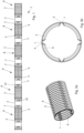
- the Fig.1 shows an exemplary embodiment of a one-piece plastic pipe 1 which is suitable for arrangement with a pipe assembly, comprising a plurality of rigid smooth pipe sections 3.
- the plastic pipe 1 further comprises a plurality of structural sections 4, which are preferably designed as flexible shaft sections, wherein the structural sections 4 have bending sections 2, which in turn have a plurality of flexible or bistable folding or wave elements arranged one behind the other along the longitudinal direction L.
- the structural sections 4 can have a reduced wall thickness compared to the smooth tube sections 3.
- a stiffening section 5 is arranged on at least one structural section 4, preferably on more than one structural section 4, in particular between two bending sections 2 adjacent along the longitudinal axis L.
- the stiffening section 5 can advantageously be longer in the longitudinal direction L than the adjacent bending section(s), preferably between 200% and 300% longer.
- the stiffening section 5 comprises at least one, preferably a plurality of, stiffening structures 6, which are designed, in particular in the form of webs or ridges, as a section-by-section interruption 7 of the wave troughs 8 in the circumferential direction, wherein the radial extent of the stiffening structures 6 preferably does not exceed the radial extent of the wave crests 9.
- the plurality of stiffening structures 6 are preferably distributed evenly over the circumference of the plastic pipe 1, wherein the stiffening structures 6 can be distributed, for example, mirror-axis-symmetrically and/or rotationally symmetrically over the circumference.
- the plastic pipe 1 preferably has a maximum length in the longitudinal direction L of 5 m, particularly preferably the length is 3 m to 5 m, very particularly preferably 2.5 m to 5 m.
- the Fig. 2a and b show a stiffening section 5 in an enlarged, perspective view.
- the stiffening section 5 comprises four stiffening structures 6, which, in particular in the form of webs or ridges, are designed as a section-wise interruption 7 of the wave troughs 8 in the circumferential direction, wherein the radial extension of the stiffening structures 6 preferably does not exceed the radial extension of the wave crests 9.
- the plurality of stiffening structures 6 are preferably evenly distributed over the circumference of the plastic pipe 1, preferably, for example, mirror-axis-symmetrical and/or rotationally symmetrical.
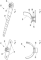
- the Fig.3 shows a fixing strip 11 on which two screw holes 12 are formed.
- the fixing strip 11 also comprises a locking cylinder 14 which is formed with four locking lugs 15, although other numbers of locking lugs 15, for example three or five, are also conceivable.
- the screw holes 12 can be used to screw a base or a surface on which the fixing strip 11 rests. A connection to a holding element can be made without tools using the locking cylinder.
- other locking means can be provided instead of locking lugs 15, for example a locking ring.
- the base area of the fixing strip 11 is larger in particular in its longitudinal extent than in its width extent, but other shapes are also conceivable, such as a round or square base area.
- the Fig.4 shows a fixing means designed as a fixing belt 13, comprising five screw holes 12.
- the screw holes 12 are formed next to one another on one side of the fixing belt 13 in relation to the longitudinal extension of the fixing belt 13, which enables an arrangement between bricks and/or on a flat roof.
- the screw holes 12 can be used to screw and/or bond to a substrate or surface on which the fixing belt 13 rests and/or lies.
- a Connection with a holding element can be made.
- the width of the fixing belt 13 is designed to decrease along the longitudinal extent of the fixing belt 13 leading to a vanishing point, but a constant width is also possible.
- the fixing belt 13 comprises a locking cylinder 14 which is designed with four locking lugs 15, although other numbers of locking lugs 15, for example three or five, are also conceivable. Likewise, other locking means can be provided instead of locking lugs 15, for example a locking ring.
- the Fig.5 shows a holding element 17, which is designed in particular as a half ring, although other designs, for example as a complete ring or curved plate, are also conceivable.
- the holding element 17 further comprises a spacer section 21, which is designed in particular as a hollow cylinder, although it is also conceivable, for example, to design the spacer section 21 as a square. Openings 23 are arranged on the spacer section 21, the height and width of which are adapted to a fastening element 18 (not shown here), which can be connected to the holding element 17 via the openings 23.
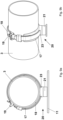
- the Fig.6 shows the cross section of a holding element 17, which is connected to a fixing means comprising a locking cylinder 14.
- the spacer section 21 of the holding element 17 has an annular groove 22 on its inner circumference, into which the locking lugs 15 of the locking cylinder 14 can engage in order to form a locking connection.
- the locking connection can be reversible or irreversible.
- the connection of the locking cylinder 14 to the spacer section 21 is preferably arranged in such a way that a fastening element 18 (not shown here) can be guided over the locking cylinder through the openings 23 of the spacer section 21.
- the openings 23 can be designed in their dimensions for a single passage of a fastening element 18, or for multiple passage.
- a fixing plate 24 is shown which is designed with an approximately square base area, although shapes such as a round base area are also conceivable.
- the fixing plate 24 comprises four screw holes 12, although a different number of screw holes 12 is also possible.
- the fixing plate 24 preferably comprises an inclined frame on its outer edge, which creates a distance from a surface on which the fixing plate 24 can be mounted.
- a pipe opening 25 is formed centrally on the fixing plate 24, the diameter of which is adapted to a plastic pipe 1.
- the pipe opening 25 is framed by a wall 26, in particular a cylindrical wall, which has a projection on the front and back of the fixing plate 24.
- the pipe opening 25 comprises a first section 27, on which the wall 26 is formed perpendicular to the base area of the fixing plate 24 and sealing means 28, in particular designed as a sealing ring, are included. Furthermore, the tube opening 25 comprises a second section 29 which is formed with an inclination which is adapted to the inclination of the last and first wave crests of the structural sections 4 along the longitudinal direction L.
- the fixing plate 24 is designed with an approximately square base, although shapes such as a round base are also conceivable.
- the fixing plate 24 comprises four screw holes 12, although a different number of screw holes 12 is also possible.
- the fixing plate 24 preferably comprises an inclined frame on its outer edge, which has a distance from a surface on which the fixing plate 24 can be mounted.
- a pipe opening 25 is formed centrally on the fixing plate 24, the diameter of which is adapted to a plastic pipe 1.
- the pipe opening 25 is framed by a, in particular cylindrical, wall 26, which has a projection on the front and back of the fixing plate 24.
- the pipe opening 25 comprises a first section 27, on which the wall 26 is formed perpendicular to the base area of the fixing plate 24 and sealing means 28, in particular designed as a sealing ring, are included.
- the pipe opening 25 also comprises a second section 29, which is formed with an incline that is adapted to the incline of the last and first wave crests of the structural sections 4 along the longitudinal direction L.
- the plastic pipe 1 is arranged in the pipe opening 25 of the fixing plate 24, wherein the inclination of the second pipe section 29 prevents the plastic pipe 1 from slipping through the fixing plate 24 and the sealing means 28 prevent the plastic pipe 1 from slipping out of the fixing plate 24 against the insertion direction.
- the Fig.9 a and b show a smooth tube section 3 of a plastic tube 1 in a fastening arrangement 20.
- the fastening arrangement 20 comprises a fixing strip 11, which is connected to the spacer section 21 of the holding element 17 via a locking cylinder 14 (not visible here).
- a fastening element 18 is guided through the openings 23 and connected to the holding element 17.
- the openings 23 are designed in such a way that the fastening element 18 can be guided through the openings 23 once or twice.
- the fastening element is designed in particular like a sleeve and comprises the smooth tube section 3, whereby it is guided in sections on the holding element 17 designed as a half ring.
- the fastening element 18 has a locking unit 19 at a first end and locking means on its base surface, wherein the locking unit 19 and the locking means enable the formation of a locking connection, preferably reversible.
- the fastening element 18 can have a tab into which the free end of the fastening element 18 can be inserted.
- the Fig. 10a shows a lateral sectional view through a pipe assembly.
- a pipe preferably a one-piece plastic pipe
- the pipe 1 has a smooth pipe section 3 at the end and a structural section 4, which is designed as a corrugated pipe section, with wave troughs 8 and wave crests 9.
- the collar element 35 comprises an outer ring 30, which is formed from two mirror-symmetrical flanks 30.1, and end sections 31, which are in particular thickened, and are designed in a hook shape such that they at least partially surround an inner ring 23.
- Fig. 10a shows a lateral sectional view through a pipe assembly.
- a pipe 1 preferably a one-piece plastic pipe
- the pipe 1 has a smooth pipe section 3 at the end and a structural section 4, which is designed as a corrugated pipe section, with wave troughs 8 and wave crests 9.
- the collar element 35 comprises an outer ring 30, which is formed from two mirror-symmetrical flanks 30.1, and end sections 31, which are in particular
- an angle ⁇ is enclosed by the base of the outer ring and an inner hook section 36 of the end section 31, which is formed at 70 to 90°, preferably 75 to 85°.
- the inner ring 32 has an inclination at its axial end, in relation to the axial direction A, which is mirror-symmetrical to the angle ⁇ . This allows a sealing ring 34 to be arranged in the recess between the outer ring 30 and the inner ring 32, the sealing ring being fixed by the angle ⁇ and the opposite inclination and being held in the groove formed by the outer ring and inner ring.
- the inner ring 32 is arranged in a form-fitting manner on the outer ring 30 and comprises a plug-in collar 33, which is designed as an inner and outer bead. On its outer bead, notches of the outer ring 30 are assigned to the plug-in collar 33 in a form-fitting manner, whereby a particularly stable connection is formed, in particular when the outer ring 30 and inner ring 32 are connected with a shrink fit.
- the tube 1 is arranged flush with the plug-in collar 33 on its inner annular bead, the plug-in collar 33 serving as a positioning aid for the two plug-in tubes 1 and being designed such that it is flush with the inner circumference of the tubes 1, thereby creating a continuous surface, for example for conducting a fluid or for accommodating cables.
- the Fig. 10c shows the collar element 35 according to the invention in a perspective view.
- the collar element 35 comprises an outer ring 30 and an inner ring 32, which are connected to one another in a form-fitting manner, in particular by shrink fitting.
- the outer ring 30 comprises two mirror-symmetrical flanks 30.1, and end sections 31, which are in particular thickened, and are designed in a hook-shaped manner such that they at least partially enclose an inner ring 23.
- the inner ring 32 comprises a plug-in collar 33, which is designed as an inner and outer bead.
- the sealing ring 34 is made of elastic material. It is not provided with friction-reducing additives or coatings. When the smooth pipe section 3 is inserted or pushed in, the axial securing of the pipe assembly and the fluid or media density are achieved essentially via the static friction of the sealing ring 34 on the outer surface of the smooth pipe. This makes it possible to connect two pipe ends to create a pipe assembly both simply and effectively.
- the inner diameter of the collar element - apart from the sealing ring - in the cooled, ready-to-use state is selected so that it is minimally larger than the outer diameter of the end-side smooth pipe section 3, so that the smooth pipe section 3 can be inserted relatively easily, but at the same time, when the sealing ring 34 passes, friction and a resulting adhesive force are generated between the collar element 35 and the pipe 1.
Landscapes
- Engineering & Computer Science (AREA)
- General Engineering & Computer Science (AREA)
- Mechanical Engineering (AREA)
- Rigid Pipes And Flexible Pipes (AREA)
Applications Claiming Priority (1)
| Application Number | Priority Date | Filing Date | Title |
|---|---|---|---|
| DE102023104539 | 2023-02-24 |
Publications (2)
| Publication Number | Publication Date |
|---|---|
| EP4421368A2 true EP4421368A2 (fr) | 2024-08-28 |
| EP4421368A3 EP4421368A3 (fr) | 2024-11-13 |
Family
ID=90059529
Family Applications (1)
| Application Number | Title | Priority Date | Filing Date |
|---|---|---|---|
| EP24159750.9A Pending EP4421368A3 (fr) | 2023-02-24 | 2024-02-26 | Ensemble de tuyaux et système de tuyau en plastique |
Country Status (1)
| Country | Link |
|---|---|
| EP (1) | EP4421368A3 (fr) |
Family Cites Families (8)
| Publication number | Priority date | Publication date | Assignee | Title |
|---|---|---|---|---|
| DE1160248B (de) * | 1959-07-13 | 1963-12-27 | Anger Kunststoff | Muffenverbindung fuer Kunststoffrohre |
| DE1989458U (de) * | 1968-04-06 | 1968-07-18 | Hell Rudolf Dr Ing Fa | Kabelbandhalter. |
| CH644436A5 (en) * | 1981-11-03 | 1984-07-31 | Marc Luisier | Device for positioning pipes in a concrete slab |
| DE4409136C2 (de) * | 1994-03-17 | 1996-12-19 | Teewen Bv | Kupplungsvorrichtung |
| DE4432584C1 (de) * | 1994-09-13 | 1996-02-29 | Inventa Ag | Polymerleitung |
| DE102007058159B4 (de) * | 2006-12-18 | 2017-01-26 | Icotek Project Gmbh & Co. Kg | Tülle zum Hindurchführen eines Kabels |
| DE202013103712U1 (de) * | 2013-08-15 | 2013-08-29 | Pflitsch Gmbh & Co. Kg | Wanddurchführung |
| DE102015121271B3 (de) * | 2015-12-07 | 2017-04-13 | Sfs Intec Holding Ag | Leitungshalter |
-
2024
- 2024-02-26 EP EP24159750.9A patent/EP4421368A3/fr active Pending
Also Published As
| Publication number | Publication date |
|---|---|
| EP4421368A3 (fr) | 2024-11-13 |
Similar Documents
| Publication | Publication Date | Title |
|---|---|---|
| EP2757299B1 (fr) | Dispositif de serrage de tuyau | |
| EP2218923A2 (fr) | Dispositif de fixation destiné à l'agencement d'un élément de tiges sur un rail de montage | |
| EP3529538B1 (fr) | Élément arqué pour système de ventilation | |
| EP0671581B1 (fr) | Dispositif de fixation pour la fixation de tuyaux ou similaires | |
| DE102011005598A1 (de) | Befestigungsvorrichtung zur Anordnung an einer Montageschiene | |
| EP2867602A1 (fr) | Tube plat et échangeur de chaleur équipé d'un tel tube plat | |
| EP0675308A1 (fr) | Manchon de tuyaux | |
| WO2006082084A1 (fr) | Echangeur thermique | |
| DE102008009633A1 (de) | Flächenelement mit mindestens einer Profilrippe | |
| WO2015117763A1 (fr) | Bride de fixation | |
| EP3064849B1 (fr) | Systeme de distribution, en particulier diffuseur d'air | |
| EP1703191A2 (fr) | Raccord de conduits | |
| EP4421368A2 (fr) | Ensemble de tuyaux et système de tuyau en plastique | |
| DE2614477A1 (de) | Loesbare rohrverbindung, insbesondere fuer mehrteilige fahrzeugauspuffrohre | |
| DE3104518A1 (de) | Anschlussarmatur | |
| DE10324160B4 (de) | Vorrichtung zum Verbinden von Flansche aufweisende Luftkanalabschnitte | |
| DE29911715U1 (de) | Abstandshalter für ein Kamin-Rauchrohr | |
| DE102008017659A1 (de) | Speicherbehälter, insbesondere Pufferspeicher für Heizungen | |
| EP1199536A2 (fr) | Echangeur de chaleur, notamment pour piscines | |
| DE19828188C1 (de) | Fassadenprofil | |
| DE102012111208A1 (de) | Spreizdübel | |
| DE29924269U1 (de) | Rohrkupplung oder Rohrschelle | |
| DE3518813A1 (de) | Flansch zur befestigung von rohren | |
| EP4382793B1 (fr) | Dispositif de serrage pour la fixation axiale d'un raccord de tuyau à manchon et raccord de tuyau à manchon et dispositif de serrage correspondant | |
| DE3832399A1 (de) | Rohrhalter und verfahren zur rohrmontage mittels eines rohrhalters |
Legal Events
| Date | Code | Title | Description |
|---|---|---|---|
| PUAI | Public reference made under article 153(3) epc to a published international application that has entered the european phase |
Free format text: ORIGINAL CODE: 0009012 |
|
| STAA | Information on the status of an ep patent application or granted ep patent |
Free format text: STATUS: THE APPLICATION HAS BEEN PUBLISHED |
|
| AK | Designated contracting states |
Kind code of ref document: A2 Designated state(s): AL AT BE BG CH CY CZ DE DK EE ES FI FR GB GR HR HU IE IS IT LI LT LU LV MC ME MK MT NL NO PL PT RO RS SE SI SK SM TR |
|
| PUAL | Search report despatched |
Free format text: ORIGINAL CODE: 0009013 |
|
| AK | Designated contracting states |
Kind code of ref document: A3 Designated state(s): AL AT BE BG CH CY CZ DE DK EE ES FI FR GB GR HR HU IE IS IT LI LT LU LV MC ME MK MT NL NO PL PT RO RS SE SI SK SM TR |
|
| RIC1 | Information provided on ipc code assigned before grant |
Ipc: F16L 25/00 20060101ALI20241008BHEP Ipc: F16L 21/03 20060101ALI20241008BHEP Ipc: F16L 21/02 20060101ALI20241008BHEP Ipc: F16L 11/12 20060101ALI20241008BHEP Ipc: F16L 11/115 20060101ALI20241008BHEP Ipc: F16L 11/11 20060101ALI20241008BHEP Ipc: F16L 5/10 20060101ALI20241008BHEP Ipc: F16L 3/137 20060101AFI20241008BHEP |
|
| STAA | Information on the status of an ep patent application or granted ep patent |
Free format text: STATUS: REQUEST FOR EXAMINATION WAS MADE |
|
| 17P | Request for examination filed |
Effective date: 20250507 |