EP4421897A1 - Elektrochemische vorrichtung und elektronische vorrichtung damit - Google Patents
Elektrochemische vorrichtung und elektronische vorrichtung damit Download PDFInfo
- Publication number
- EP4421897A1 EP4421897A1 EP22884905.5A EP22884905A EP4421897A1 EP 4421897 A1 EP4421897 A1 EP 4421897A1 EP 22884905 A EP22884905 A EP 22884905A EP 4421897 A1 EP4421897 A1 EP 4421897A1
- Authority
- EP
- European Patent Office
- Prior art keywords
- positive electrode
- electrode material
- lithium
- electrochemical apparatus
- electrolyte
- Prior art date
- Legal status (The legal status is an assumption and is not a legal conclusion. Google has not performed a legal analysis and makes no representation as to the accuracy of the status listed.)
- Pending
Links
Images
Classifications
-
- H—ELECTRICITY
- H01—ELECTRIC ELEMENTS
- H01M—PROCESSES OR MEANS, e.g. BATTERIES, FOR THE DIRECT CONVERSION OF CHEMICAL ENERGY INTO ELECTRICAL ENERGY
- H01M4/00—Electrodes
- H01M4/02—Electrodes composed of, or comprising, active material
- H01M4/36—Selection of substances as active materials, active masses, active liquids
- H01M4/48—Selection of substances as active materials, active masses, active liquids of inorganic oxides or hydroxides
- H01M4/50—Selection of substances as active materials, active masses, active liquids of inorganic oxides or hydroxides of manganese
- H01M4/505—Selection of substances as active materials, active masses, active liquids of inorganic oxides or hydroxides of manganese of mixed oxides or hydroxides containing manganese for inserting or intercalating light metals, e.g. LiMn2O4 or LiMn2OxFy
-
- H—ELECTRICITY
- H01—ELECTRIC ELEMENTS
- H01M—PROCESSES OR MEANS, e.g. BATTERIES, FOR THE DIRECT CONVERSION OF CHEMICAL ENERGY INTO ELECTRICAL ENERGY
- H01M10/00—Secondary cells; Manufacture thereof
- H01M10/05—Accumulators with non-aqueous electrolyte
- H01M10/052—Li-accumulators
- H01M10/0525—Rocking-chair batteries, i.e. batteries with lithium insertion or intercalation in both electrodes; Lithium-ion batteries
-
- H—ELECTRICITY
- H01—ELECTRIC ELEMENTS
- H01M—PROCESSES OR MEANS, e.g. BATTERIES, FOR THE DIRECT CONVERSION OF CHEMICAL ENERGY INTO ELECTRICAL ENERGY
- H01M10/00—Secondary cells; Manufacture thereof
- H01M10/05—Accumulators with non-aqueous electrolyte
- H01M10/056—Accumulators with non-aqueous electrolyte characterised by the materials used as electrolytes, e.g. mixed inorganic/organic electrolytes
- H01M10/0564—Accumulators with non-aqueous electrolyte characterised by the materials used as electrolytes, e.g. mixed inorganic/organic electrolytes the electrolyte being constituted of organic materials only
- H01M10/0566—Liquid materials
- H01M10/0567—Liquid materials characterised by the additives
-
- H—ELECTRICITY
- H01—ELECTRIC ELEMENTS
- H01M—PROCESSES OR MEANS, e.g. BATTERIES, FOR THE DIRECT CONVERSION OF CHEMICAL ENERGY INTO ELECTRICAL ENERGY
- H01M4/00—Electrodes
- H01M4/02—Electrodes composed of, or comprising, active material
- H01M4/13—Electrodes for accumulators with non-aqueous electrolyte, e.g. for lithium-accumulators; Processes of manufacture thereof
- H01M4/131—Electrodes based on mixed oxides or hydroxides, or on mixtures of oxides or hydroxides, e.g. LiCoOx
-
- H—ELECTRICITY
- H01—ELECTRIC ELEMENTS
- H01M—PROCESSES OR MEANS, e.g. BATTERIES, FOR THE DIRECT CONVERSION OF CHEMICAL ENERGY INTO ELECTRICAL ENERGY
- H01M4/00—Electrodes
- H01M4/02—Electrodes composed of, or comprising, active material
- H01M4/13—Electrodes for accumulators with non-aqueous electrolyte, e.g. for lithium-accumulators; Processes of manufacture thereof
- H01M4/136—Electrodes based on inorganic compounds other than oxides or hydroxides, e.g. sulfides, selenides, tellurides, halogenides or LiCoFy
-
- H—ELECTRICITY
- H01—ELECTRIC ELEMENTS
- H01M—PROCESSES OR MEANS, e.g. BATTERIES, FOR THE DIRECT CONVERSION OF CHEMICAL ENERGY INTO ELECTRICAL ENERGY
- H01M4/00—Electrodes
- H01M4/02—Electrodes composed of, or comprising, active material
- H01M4/36—Selection of substances as active materials, active masses, active liquids
- H01M4/362—Composites
- H01M4/364—Composites as mixtures
-
- H—ELECTRICITY
- H01—ELECTRIC ELEMENTS
- H01M—PROCESSES OR MEANS, e.g. BATTERIES, FOR THE DIRECT CONVERSION OF CHEMICAL ENERGY INTO ELECTRICAL ENERGY
- H01M4/00—Electrodes
- H01M4/02—Electrodes composed of, or comprising, active material
- H01M4/36—Selection of substances as active materials, active masses, active liquids
- H01M4/48—Selection of substances as active materials, active masses, active liquids of inorganic oxides or hydroxides
- H01M4/52—Selection of substances as active materials, active masses, active liquids of inorganic oxides or hydroxides of nickel, cobalt or iron
- H01M4/525—Selection of substances as active materials, active masses, active liquids of inorganic oxides or hydroxides of nickel, cobalt or iron of mixed oxides or hydroxides containing iron, cobalt or nickel for inserting or intercalating light metals, e.g. LiNiO2, LiCoO2 or LiCoOxFy
-
- H—ELECTRICITY
- H01—ELECTRIC ELEMENTS
- H01M—PROCESSES OR MEANS, e.g. BATTERIES, FOR THE DIRECT CONVERSION OF CHEMICAL ENERGY INTO ELECTRICAL ENERGY
- H01M4/00—Electrodes
- H01M4/02—Electrodes composed of, or comprising, active material
- H01M4/36—Selection of substances as active materials, active masses, active liquids
- H01M4/58—Selection of substances as active materials, active masses, active liquids of inorganic compounds other than oxides or hydroxides, e.g. sulfides, selenides, tellurides, halogenides or LiCoFy; of polyanionic structures, e.g. phosphates, silicates or borates
- H01M4/5825—Oxygenated metallic salts or polyanionic structures, e.g. borates, phosphates, silicates, olivines
-
- H—ELECTRICITY
- H01—ELECTRIC ELEMENTS
- H01M—PROCESSES OR MEANS, e.g. BATTERIES, FOR THE DIRECT CONVERSION OF CHEMICAL ENERGY INTO ELECTRICAL ENERGY
- H01M4/00—Electrodes
- H01M4/02—Electrodes composed of, or comprising, active material
- H01M2004/021—Physical characteristics, e.g. porosity, surface area
-
- H—ELECTRICITY
- H01—ELECTRIC ELEMENTS
- H01M—PROCESSES OR MEANS, e.g. BATTERIES, FOR THE DIRECT CONVERSION OF CHEMICAL ENERGY INTO ELECTRICAL ENERGY
- H01M4/00—Electrodes
- H01M4/02—Electrodes composed of, or comprising, active material
- H01M2004/026—Electrodes composed of, or comprising, active material characterised by the polarity
- H01M2004/028—Positive electrodes
-
- Y—GENERAL TAGGING OF NEW TECHNOLOGICAL DEVELOPMENTS; GENERAL TAGGING OF CROSS-SECTIONAL TECHNOLOGIES SPANNING OVER SEVERAL SECTIONS OF THE IPC; TECHNICAL SUBJECTS COVERED BY FORMER USPC CROSS-REFERENCE ART COLLECTIONS [XRACs] AND DIGESTS
- Y02—TECHNOLOGIES OR APPLICATIONS FOR MITIGATION OR ADAPTATION AGAINST CLIMATE CHANGE
- Y02E—REDUCTION OF GREENHOUSE GAS [GHG] EMISSIONS, RELATED TO ENERGY GENERATION, TRANSMISSION OR DISTRIBUTION
- Y02E60/00—Enabling technologies; Technologies with a potential or indirect contribution to GHG emissions mitigation
- Y02E60/10—Energy storage using batteries
Definitions
- This application relates to the field of energy storage, specifically to an electrochemical apparatus and an electronic apparatus including the same, and in particular to a lithium-ion battery.
- a solid electrolyte interface (SEI) is formed on a surface of a negative electrode, causing irreversible capacity loss and reducing the energy density of the lithium-ion energy storage device.
- SEI solid electrolyte interface
- a lithium-ion energy storage device with a graphite negative electrode about 10% of the active lithium source is consumed in the first cycle.
- a negative electrode is made of a negative electrode material with a high specific capacity, such as alloys (silicon-alloy, tin-alloy, and the like), oxides (silicon oxide and tin oxide), and amorphous carbon, much more of the active lithium source is consumed. Therefore, appropriate lithium supplementation methods are of great significance for further increasing the energy density of the lithium-ion energy storage device.
- This application provides an electrochemical apparatus and an electronic apparatus with improved cycling performance and increased energy density, to resolve the problem in the prior art to some extent.
- this application provides an electrochemical apparatus.
- the electrochemical apparatus includes a positive electrode, a negative electrode, and an electrolyte.
- the positive electrode includes a positive electrode current collector and a positive electrode material layer on at least one surface of the positive electrode current collector.
- the positive electrode material layer includes a first positive electrode material shown in Formula (I): Li 1+x Fe y Mn z M 1-y-z PO 4-t A t Formula (I), where
- the positive electrode satisfies Formula (2): 1.5 ⁇ R ⁇ P / Q ⁇ 10
- R 3.5 ⁇ .
- a mass ratio of the first positive electrode material to the second positive electrode material is 5:1 to 99:1.
- a percentage of the first positive electrode material is 80% to 98%.
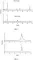
- the second positive electrode material has a characteristic diffraction peak A in an X-ray diffraction pattern in a range of 15° to 16° and/or a characteristic diffraction peak B in a range of 18° to 19°, and a ratio of I A /I B of an intensity I A of the characteristic diffraction peak A to an intensity I B of the characteristic diffraction peak B satisfies Formula (3): 0 ⁇ I A /I B ⁇ 0.2 Formula (3).
- the characteristic diffraction peak A and the characteristic diffraction peak B both shift toward lower angles, with a shift magnitude less than 0.5°.
- the electrolyte includes vinyl carbonate, where based on a total mass of the electrolyte, a percentage of the vinyl carbonate is 0.05% to 5%.
- this application provides an electronic apparatus, including the electrochemical apparatus described according to some embodiments of this application.
- This application provides a lithium-ion secondary battery including a positive-electrode lithium-supplementing material.
- a surface of the second positive electrode material used in this application has a small amount of free lithium and good processing performance.
- this material has a higher specific capacity than the first positive electrode material and can release a large amount of lithium ions during the first charge to supplement active lithium.
- a combination of this material and the first positive electrode material can effectively improve the energy density and cycle life of the battery.
- the comprehensive design of the sheet resistance, compacted density, and surface density of the positive electrode in this application can significantly improve the cycle life and energy density of the lithium-ion secondary battery.
- the additive vinyl carbonate is added into the electrolyte, allowing the negative electrode to form a more uniformly dense SEI film and inhibiting the continuous loss of the active lithium, thus further prolonging the cycle life of the lithium-ion secondary battery.
- a list of items connected by the terms “one of”, “one piece of”, “one kind of” or other similar terms may mean any one of the listed items.
- the phrase “one of A and B” means only A or only B.
- the phrase “one of A, B, and C” means only A, only B, or only C.
- the item A may include a single element or a plurality of elements.
- the item B may include a single element or a plurality of elements.
- the item C may include a single element or a plurality of elements.
- an item list connected by the terms “at least one of”, “at least one piece of”, “at least one kind of” or other similar terms may mean any combination of the listed items.
- the phrase “at least one of A and B” means only A; only B; or A and B.
- the phrase “at least one of A, B, or C” means only A; only B; only C; A and B (exclusive of C); A and C (exclusive of B); B and C (exclusive of A); or all of A, B, and C.
- the item A may include a single element or a plurality of elements.
- the item B may include a single element or a plurality of elements.
- the item C may include a single element or a plurality of elements.
- this application provides an electrochemical apparatus.
- the electrochemical apparatus includes a positive electrode, a negative electrode, and an electrolyte.
- the positive electrode includes a positive electrode current collector and a positive electrode material layer on at least one surface of the positive electrode current collector, and the positive electrode material layer includes a first positive electrode material shown in Formula (I): Li 1+x Fe y Mn z M 1-y-z PO 4-t A t Formula (I), where
- the resistance R of the positive electrode is a resistance value measured using the direct-current two-probe method, where a contact area between the probe and the positive electrode is 49 ⁇ mm 2 .
- a contact area between the probe and the positive electrode is 49 ⁇ mm 2 .
- upper and lower sides of the positive electrode are clamped between two conductive terminals of an electrode plate resistance tester and then fixed by applying pressure.
- the diameter of the conductive terminals is 14 mm, and the applied pressure is 15 MPa to 27 MPa.
- the positive electrode resistance tester is a HIOKI BT23562 internal resistance tester.
- the volume v of the positive electrode material layer may be a product of the area A r of the positive electrode material layer and the thickness of the positive electrode material layer.
- the positive electrode material layer is located on a surface of the positive electrode current collector. In some embodiments, the positive electrode material layer is located on both surfaces of the positive electrode current collector.
- the first positive electrode material includes at least one of LiFePO 4 , LiFe 0.5 Mn 0.5 PO 4 , Li 0.9 Fe 0.5 Mn 0.45 Ti 0.05 PO 4 , Li 0.9 Fe 0.5 Mn 0.45 Ti 0.04 Zr 0.01 PO 4 , or Li 0.95 FePO 3.95 F 0.05 .
- the second positive electrode material includes at least one of LiMnO 2 , LiMn 0.9 Ni 0.1 O 2 , LiMn 0.9 Ni 0.05 Cr 0.05 O 2 , Li 0.95 MnO 1.95 F 0.05 , Li 0.95 MnO 1.9 S 0.05 F 0.05 .
- 1.5 ⁇ R ⁇ P/Q In some embodiments, 1.5 ⁇ R ⁇ P/Q ⁇ 10. In some embodiments, a value of R ⁇ P/Q is 0.5, 1, 1.5, 2, 2.5, 3, 3.5, 4, 5, 6, 7, 8, 9, 10, 11, 12, 13, 14, 15, 16, or in a range defined by any two of these values.
- R ⁇ 3.5 ⁇ .
- R is 0.2 ⁇ , 0.5 ⁇ , 1 ⁇ , 1.2 ⁇ , 1.5 ⁇ , 1.8 ⁇ , 2.0 ⁇ , 2.2 ⁇ , 2.5 ⁇ , 3.0 ⁇ , 3.2 ⁇ , 3.5 ⁇ , or in a range defined by any two of these values. R being in the foregoing range is conducive to improving the cycling performance and rate performance of the lithium-ion secondary battery.
- 1.6 g/cm 3 ⁇ P ⁇ 2.6 g/cm 3 .
- P is 1.6 g/cm 3 , 1.8 g/cm 3 , 2.0 g/cm 3 , 2.2 g/cm 3 , 2.4 g/cm 3 , 2.6 g/cm 3 , or in a range defined by any two of these values. P being in the foregoing range is conducive to migration of electrons and ions in the positive electrode, thus improving the cycling performance of the lithium-ion secondary battery.
- 0.16 g/1540.25 mm 2 ⁇ Q ⁇ 0.45 g/1540.25 mm 2 .
- Q is 0.16 g/1540.25 mm 2 , 0.18 g/1540.25 mm 2 , 0.2 g/1540.25 mm 2 , 0.25 g/1540.25 mm 2 , 0.28 g/1540.25 mm 2 , 0.30 g/1540.25 mm 2 , 0.34 g/1540.25 mm 2 , 0.36 g/1540.25 mm 2 , 0.38 g/1540.25 mm 2 , 0.40 g/1540.25 mm 2 , 0.42 g/1540.25 mm 2 , 0.45 g/1540.25 mm 2 , or in a range defined by any two of these values. Q being in the foregoing range can improve the cycling performance and rate performance of the lithium-ion secondary battery under the premise of ensuring charge/discharge capacity.
- a mass ratio of the first positive electrode material to the second positive electrode material is 5:1 to 99:1. In some embodiments, the mass ratio of the first positive electrode material to the second positive electrode material is 5:1, 9:1, 10:1, 15:1, 20:1, 25:1, 30:1, 35:1, 40:1, 45:1, 50:1, 55:1, 60:1, 65:1, 70:1, 75:1, 80:1, 85:1, 90:1, 95:1, 99:1, or in a range defined by any two of these values.
- the mass ratio of the first positive electrode material to the second positive electrode material is in the foregoing range, the positive electrode includes the first positive electrode material of high concentration, allowing for higher structural stability of the positive electrode. This can alleviate capacity loss and impedance increase caused by damage to the positive electrode material structure, thus maintaining cycling stability and kinetic performance of the lithium-ion battery.
- a percentage of the first positive electrode material is 80% to 98%. In some embodiments, based on the total mass of the positive electrode material layer, the percentage of the first positive electrode material is 80%, 82%, 84%, 85%, 88%, 90%, 92%, 94%, 96%, 98%, or in a range defined by any two of these values.
- the second positive electrode material has a characteristic diffraction peak A in an X-ray diffraction pattern in a range of 15° to 16° and/or a characteristic diffraction peak B in a range of 18° to 19°, and a ratio of I A /I B of an intensity I A of the characteristic diffraction peak A to an intensity I B of the characteristic diffraction peak B satisfies Formula (3): 0 ⁇ I A /I B ⁇ 0.2 Formula (3).
- the value of I A /I B is 0.1, 0.12, 0.14, 0.16, 0.18, 0.2, or in a range defined by any two of these values.
- the characteristic diffraction peak A and the characteristic diffraction peak B both shift toward lower angles, with a shift magnitude less than 0.5°.
- the shift magnitude is 0.1°, 0.2°, 0.3°, 0.4°, 0.45°, or in a range defined by any two of these values.
- the positive electrode material layer includes a conductive agent.
- the conductive agent includes at least one of graphite, superconducting carbon, acetylene black, carbon black, Ketjen black, carbon dots, carbon nanotubes, graphene, or carbon nanofiber.
- a percentage of the conductive agent is 0.5% to 20%. In some embodiments, based on the total mass of the positive electrode material layer, the percentage of the conductive agent is 0.5%, 1%, 5%, 8%, 10%, 12%, 14%, 16%, 18%, 20%, or in a range defined by any two of these values.
- the positive electrode material layer includes a binder.
- the binder includes at least one of styrene-butadiene rubber (SBR), water-based acrylic resin, carboxymethyl cellulose (CMC), polyvinylidene fluoride (PVDF), polytetrafluoroethylene (PTFE), polyvinyl butyral (PVB), ethylenevinyl acetate copolymer (EVA), or polyvinyl alcohol (PVA).
- SBR styrene-butadiene rubber
- CMC carboxymethyl cellulose
- PVDF polyvinylidene fluoride
- PTFE polytetrafluoroethylene
- PVB polyvinyl butyral
- EVA ethylenevinyl acetate copolymer
- PVA polyvinyl alcohol
- a percentage of the binder is 0.1% to 2.5%. In some embodiments, based on the total mass of the positive electrode material layer, the percentage of the binder is 0.1%, 0.2%, 0.5%, 0.8%, 1%, 1.2%, 1.5%, 1.8%, 2%, 2.5%, or in a range defined by any two of these values.
- the positive electrode current collector may be a metal foil or a porous metal plate. In some embodiments, the positive electrode current collector includes a foil or a porous plate of metal such as aluminum, copper, nickel, titanium, or silver or their alloys. In some embodiments, the positive electrode current collector includes at least one of a copper foil or an aluminum foil.
- thickness of the positive electrode current collector is 5 ⁇ m to 20 ⁇ m. In some embodiments, the thickness of the positive electrode current collector is 5 ⁇ m, 8 ⁇ m, 10 ⁇ m, 12 ⁇ m, 15 ⁇ m, 18 ⁇ m, 20 ⁇ m, or in a range defined by any two of these values.
- the positive electrode may be obtained by using the following method: mixing the positive electrode active material, the conductive agent, and the binder in a solvent to prepare an active material compound, and applying the active material compound on the current collector.
- the solvent may include N-methylpyrrolidone or the like, but is not limited thereto.
- the positive electrode of this application can fully exert a synergistic effect between the first positive electrode material and the second positive electrode material.
- the second positive electrode material features a high specific capacity and low initial coulombic efficiency during the first charge, active lithium loss caused by the formed SEI is effectively compensated for.
- the first positive electrode material used in this application has a stable structure, a small change in volume during charge and discharge, and good cycling stability.
- the design of the sheet resistance, compacted density, and surface density of the positive electrode can further increase the energy density of the lithium-ion secondary battery, improve the rate performance, and prolong the cycle life. Therefore, the use of the positive electrode of this application allows the lithium-ion secondary battery to have high energy density, good rate performance, and long cycle life.
- the sheet resistance, compacted density, and single-sided surface density of the positive electrode are key parameters for designing and manufacturing the lithium-ion secondary battery.
- An excessively large sheet resistance of the positive electrode deteriorates the cycling performance and rate performance of the lithium-ion secondary battery.
- An excessively large or small compacted density worsens the cycling performance and rate performance of the battery.
- An excessively large single-sided surface density of the positive electrode reduces the cycle life of the battery and affects the infiltration of the electrolyte, thus affecting the rate performance of the battery, especially reducing the discharge capacity of the battery at a high rate.
- An excessively small single-sided surface density of the positive electrode increases, with the same battery capacity, the lengths of the current collector and separator as well as the ohmic internal resistance of the battery.
- the positive electrode includes both the first positive electrode material and the second positive electrode material
- the comprehensive design of parameters such as the sheet resistance, compacted density, and single-sided surface density of the positive electrode allows the electrochemical performance of the lithium-ion secondary battery to achieve the expected result.
- the electrolyte used in the electrochemical apparatus of this application includes an electrolytic salt and a solvent for dissolving the electrolytic salt.
- the electrolyte includes an additive, and the additive includes vinyl carbonate, where based on a total mass of the electrolyte, a percentage of the vinyl carbonate is 0.05% to 5%.
- the percentage of the vinyl carbonate is 0.05%, 1%, 2%, 3%, 4%, 5%, or in a range defined by any two of these values.
- the cycling performance of the lithium-ion secondary battery can be further improved and the energy density can be further increased.
- the electrolyte may further include another additive, which can be arbitrarily used as an additive of the lithium-ion secondary battery. This is not specifically limited by this application and can be selected based on actual requirements.
- the another additive includes at least one of vinyl ethylene carbonate (VEC), succinonitrile (SN), adiponitrile (AND), 1,3-propanesultone (PST), sulfonate cyclic quaternary ammonium salt, trimethylsilyl phosphate (TMSP), or trimethylsilyl borate (TMSB).
- the electrolyte further includes a non-aqueous solvent that can be arbitrarily used as a solvent of the electrolyte.
- the non-aqueous solvent includes, but is not limited to, one or more of the following: cyclic carbonate, linear carbonate, cyclic carboxylate, linear carboxylate, cyclic ether, linear ether, a phosphorus-containing organic solvent, a sulfur-containing organic solvent, and an aromatic fluorine-containing solvent.
- the non-aqueous solvent includes at least one of ethylene carbonate (EC), propylene carbonate (PC), ethyl methyl carbonate (EMC), diethyl carbonate (DEC), dimethyl carbonate (DMC), dipropyl carbonate (DPC), methyl propyl carbonate (MPC), ethyl propyl carbonate (EPC), butylene carbonate (BC), fluoroethylene carbonate (FEC), methyl formate (MF), methyl acetate (MA), ethyl acetate (EA), propyl acetate (PA), methyl propionate (MP), ethyl propionate (EP), propyl propionate (PP), methyl butyrate (MB), ethyl butyrate (EB), 1,4-butyrolactone (GBL), sulfolane (SF), methyl sulfonyl methane (MSM), ethyl methanesulfonate (EMS), or dieth
- the electrolytic salt is not particularly limited.
- the electrolytic salt includes a lithium salt.
- An example of the electrolytic salt may include, but is not limited to lithium hexafluorophosphate (LiPF 6 ), lithium tetrafluoroborate (LiBF 4 ), lithium perchlorate (LiClO 4 ), lithium hexafluoroarsenate (LiAsF 6 ), lithium bis(fluorosulfonyl)imide (LiFSI), lithium bistrifluoromethanesulfonimide (LiTFSI), lithium trifluoromethanesulfonate (LiTFS), lithium difluoro(oxalato)borate (LiDFOB), lithium dioxalate borate (LiBOB), lithium difluorophosphate (LiPO 2 F 2 ), lithium difluoro(dioxalato)phosphate (LiDFOP), or lithium tetrafluor
- the percentage of the electrolytic salt is not particularly limited, provided that the effects of this application are not impaired.
- the total molar concentration of lithium in the electrolyte is greater than 0.3 mol/L, greater than 0.4 mol/L, or greater than 0.5 mol/L.
- the total molar concentration of lithium in the electrolyte is less than 3 mol/L, less than 2.5 mol/L, or less than 2.0 mol/L.
- the total molar concentration of lithium in the electrolyte falls within a range defined by any two of the foregoing values. When the concentration of the electrolytic salt falls within the foregoing range, the amount of lithium as charged particles would not be excessively small, and the viscosity can be controlled within an appropriate range, so as to ensure good conductivity.
- the negative electrode includes a negative electrode current collector and a negative electrode active substance layer located on one or two surfaces of the negative electrode current collector.
- the negative electrode active substance layer includes a negative electrode active substance.
- the negative electrode active substance layer may be one or more layers, and each of the plurality of layers of the negative electrode active substance may include the same or different negative electrode active substances.
- the negative electrode active substance is any substance capable of reversibly intercalating and deintercalating metal ions such as lithium ions.
- a rechargeable capacity of the negative electrode active substance is greater than a discharge capacity of the negative electrode active substance to prevent lithium metal from unexpectedly precipitating onto the negative electrode during charge.
- Examples of the negative electrode current collector serving as a current collector maintaining a negative electrode active substance include, but are not limited to metal materials such as aluminum, copper, nickel, stainless steel, and nickel-plated steel. In some embodiments, the negative electrode current collector is copper.
- the negative electrode current collector may take forms including but not limited to a metal foil, a metal cylinder, a metal coil, a metal plate, a metal foil, a sheet metal mesh, a punched metal, a foamed metal, or the like.
- the negative electrode current collector is a metal film.
- the negative electrode current collector is a copper foil.
- the negative electrode current collector is a rolled copper foil based on a rolling method or an electrolytic copper foil based on an electrolytic method.
- a thickness of the negative electrode current collector is greater than 1 ⁇ m or greater than 5 ⁇ m. In some embodiments, the thickness of the negative electrode current collector is less than 100 ⁇ m or less than 50 ⁇ m. In some embodiments, the thickness of the negative electrode current collector falls within a range defined by any two of the foregoing values.
- the negative electrode active substance is not particularly limited, provided that it can suck and release lithium ions.
- Examples of the negative electrode active substance may include, but are not limited to carbon materials such as natural graphite and artificial graphite; metals such as silicon (Si) and tin (Sn); or oxides of metal elements such as Si and Sn.
- the negative electrode active substance may be used alone or in combination.
- the negative electrode active substance layer may further include a negative electrode binder.
- the negative electrode binder can improve binding between particles of the negative electrode active substance and binding between the negative electrode active substance and the current collector.
- the type of the negative electrode binder is not particularly limited, provided that its material is stable to the electrolyte or a solvent used in manufacturing of the electrode.
- the negative electrode binder includes a resin binder. Examples of the resin binder include, but are not limited to fluororesin, polyacrylonitrile (PAN), polyimide resin, acrylic resin, and polyolefin resin.
- the negative electrode binder includes but is not limited to carboxymethyl cellulose (CMC) or its salt, styrene-butadiene rubber (SBR), polyacrylic acid (PAA) or its salt, or polyvinyl alcohol.
- CMC carboxymethyl cellulose
- SBR styrene-butadiene rubber
- PAA polyacrylic acid
- the negative electrode may be prepared by using the following method: applying a negative electrode mixture slurry including the negative electrode active substance, the resin binder, and the like on the negative electrode current collector, and after drying, and performing rolling to form a negative electrode active substance layer on both sides of the negative electrode current collector, thereby obtaining the negative electrode.
- a separator is typically provided between the positive electrode and the negative electrode.
- the electrolyte of this application typically infiltrates the separator.
- the material and shape of the separator are not particularly limited, provided that the separator does not significantly impair the effects of this application.
- the separator may be a resin, glass fiber, inorganic substance, or the like that is formed by a material stable to the electrolyte of this application.
- the separator includes a porous sheet or nonwoven fabric-like substance having an excellent fluid retention property, or the like.
- Examples of the material of the resin or glass fiber separator may include, but are not limited to, polyolefin, aromatic polyamide, polytetrafluoroethylene, and polyethersulfone.
- the polyolefin is polyethylene or polypropylene.
- the polyolefin is polypropylene.
- the material of the separator may be used alone or in any combination.
- the separator may alternatively be a material formed by stacking the foregoing materials, and an example thereof includes, but is not limited to, a three-layer separator formed by stacking polypropylene, polyethylene, and polypropylene in order.
- Examples of the material of the inorganic substance may include, but are not limited to, oxides such as aluminum oxide and silicon dioxide, nitrides such as aluminum nitride and silicon nitride, and sulfates (for example, barium sulfate and calcium sulfate).
- the form of the inorganic substance may include, but is not limited to, a granular or fibrous form.
- the form of the separator may be a thin-film form, and examples thereof include, but are not limited to, a nonwoven fabric, a woven fabric, and a microporous film.
- the separator has a pore diameter of 0.01 ⁇ m to 1 ⁇ m and a thickness of 5 ⁇ m to 50 ⁇ m.
- the following separator may alternatively be used: a separator that is obtained by using a resin-based binder to form a composite porous layer including inorganic particles on the surface of the positive electrode and/or the negative electrode, for example, a separator that is obtained by using fluororesin as a binder to form a porous layer on both surfaces of the positive electrode with alumina particles of which 90% have a particle size less than 1 ⁇ m.
- the thickness of the separator is random. In some embodiments, the thickness of the separator is greater than 1 ⁇ m, greater than 5 ⁇ m, or greater than 8 ⁇ m. In some embodiments, the thickness of the separator is less than 50 ⁇ m, less than 40 ⁇ m, or less than 30 ⁇ m. In some embodiments, the thickness of the separator falls within a range defined by any two of the foregoing values. When the thickness of the separator falls within the foregoing range, its insulation performance and mechanical strength can be ensured, and the rate performance and energy density of the electrochemical apparatus can be also ensured.
- the porosity of the separator is random. In some embodiments, the porosity of the separator is greater than 10%, greater than 15%, or greater than 20%. In some embodiments, the porosity of the separator is less than 60%, less than 50%, or less than 45%. In some embodiments, the porosity of the separator falls within a range defined by any two of the foregoing values. When the porosity of the separator falls within the foregoing range, its insulation performance the mechanical strength can be ensured and film resistance can be suppressed, so that the electrochemical apparatus has good safety performance.
- the average pore diameter of the separator is also random. In some embodiments, the average pore diameter of the separator is less than 0.5 ⁇ m or less than 0.2 ⁇ m. In some embodiments, the average pore diameter of the separator is greater than 0.05 ⁇ m. In some embodiments, the average pore diameter of the separator falls within a range defined by any two of the foregoing values. If the average pore diameter of the separator exceeds the foregoing range, a short circuit is likely to occur. When the average pore diameter of the separator falls within the foregoing range, the electrochemical apparatus has good safety performance.
- the electrochemical apparatus includes any apparatus in which an electrochemical reaction takes place.
- the apparatus include all types of primary batteries, secondary batteries, fuel batteries, solar batteries, or capacitors.
- the electrochemical apparatus is a lithium secondary battery, including a lithium metal secondary battery or a lithium-ion secondary battery.
- This application further provides an electronic apparatus, including the electrochemical apparatus described according to this application.
- the electrochemical apparatus of this application is not particularly limited to any purpose, and may be used for any known electronic apparatus in the prior art.
- the electrochemical apparatus of this application may be used without limitation in notebook computers, pen-input computers, mobile computers, electronic book players, portable telephones, portable fax machines, portable copiers, portable printers, stereo headsets, video recorders, liquid crystal display televisions, portable cleaners, portable CD players, mini-disc players, transceivers, electronic notebooks, calculators, storage cards, portable recorders, radios, backup power sources, motors, automobiles, motorcycles, motor bicycles, bicycles, lighting appliances, toys, game machines, clocks, electric tools, flash lamps, cameras, large household batteries, lithium-ion capacitors, and the like.
- Negative electrode active material artificial graphite, thickener carboxymethyl cellulose (CMC) sodium, binder (SBR), and conductive carbon black were mixed in a mass ratio of 95.7:1.0:1.8:1.5, added into a solvent deionized water, and stirred in a vacuum mixer to obtain a negative electrode slurry.
- the negative electrode slurry was uniformly applied onto a negative electrode current collector copper foil. Then the copper foil was transferred to an oven for drying at 120°C, followed by cold-pressing, and cutting, welding with a tab, to obtain a negative electrode.
- First positive electrode material LiFePO 4 , second positive electrode material LiMnO 2 , binder PVDF, and conductive carbon black were mixed, added in a mass ratio of 90.4:6.0:2.1:1.5 into a solvent N-methylpyrrolidone (NMP), and stirred into a uniform transparent system under vacuum, to obtain a positive electrode slurry.
- the positive electrode slurry was uniformly applied onto a positive electrode current collector aluminum foil. Then the aluminum foil was transferred to an oven for drying at 120°C, followed by cold pressing, slitting, and welding with a tab, to obtain a positive electrode.
- a percentage of the first positive electrode material LiFePO 4 was 90.4% and a percentage of the second positive electrode material LiMnO 2 was 6.0%.
- Ethylene carbonate (EC), ethyl methyl carbonate (EMC), and diethyl carbonate (DEC) were mixed to uniformity in a volume ratio of 1:1:1, to obtain an organic solvent.
- LiPF 6 was dissolved in the foregoing organic solvent to obtain a basic electrolyte, where a concentration of LiPF 6 in the basic electrolyte was 1 mol/L.
- Vinyl carbonate was added into the basic electrolyte and mixed to uniformity to obtain an electrolyte, where based on a total mass of the electrolyte, a percentage of the vinyl carbonate was 3%.
- a polyethylene porous membrane with an aluminum oxide coating was used as a separator with a thickness of 9 ⁇ m.
- the obtained positive electrode, separator, negative electrode were wound in order and placed in an outer packaging foil, with an injection opening left.
- An electrolyte was injected via the injection opening, followed by processes such as packaging, formation, and capacity grading, to obtain a lithium-ion battery.
- Examples 2 to 16 were different from Example 1 in the type and relevant performance parameter of the positive electrode material and the percentage of the additive in the electrolyte. See Table 1 for details.
- Comparative example 1 was different from Example 1 in that the positive electrode material in Comparative example 1 included only LiFePO 4 .
- Comparative example 2 was different from Example 1 in that the positive electrode material in Comparative example 2 included only LiMnO 2 .
- Comparative examples 3 and 4 were different from Example 1 in a mass ratio of the first positive electrode material to the second positive electrode material in the positive electrode. See Table 1 for details.
- Comparative examples 5 and 6 were different from Example 1 in the sheet resistance, compacted density, and single-sided surface density of the positive electrode. See Table 1 for details.
- Comparative examples 7 and 8 were different from Example 1 in the mass percentage of the vinyl carbonate in the electrolyte. See Table 1 for details.
- a HIOKI BT23562 resistance tester was used to test the sheet resistance of the positive electrode.
- the test method was as follows: clamping the positive electrode between two conductive terminals of the internal resistance tester, applying pressure to fix the positive electrode, and testing a resistance R of the positive electrode.
- the diameter of the conductive terminals was 14 mm, the applied pressure was 15 MPa to 27 MPa, and the sampling time range was 5s to 17s.
- the lithium-ion secondary battery was constant-current charged to 4.2 V at a rate of 1C, constant-voltage charged to a current less than or equal to 0.05C, and then constant-current discharged to 2.5 V at a rate of 1C. This was a charge and discharge cycle.
- a discharge capacity of the lithium-ion secondary battery for the first cycle was recorded.
- the lithium-ion secondary battery was subjected to charge and discharge recycling according to the foregoing method, a discharge capacity for each cycle was recorded until the discharge capacity of the lithium-ion secondary battery degraded to 80% of a discharge capacity for the first cycle, and the number of charge and discharge cycles at this moment was recorded.
- the lithium-ion secondary battery was constant-current charged to 4.2 V at a rate of 0.5C, then constant-voltage charged to a current less than or equal to 0.05C, and then constant-current discharged to 2.5 V at a rate of 0.5C. A 0.5C-rate discharge capacity was recorded.
- the lithium-ion secondary battery was constant-current charged to 4.2 V at a rate of 0.5C, then constant-voltage charged to a current less than or equal to 0.05C, and then constant-current discharged to 2.5 V at a rate of 0.2C. A 2C-rate discharge capacity was recorded.
- 2C-rate discharge capacity retention rate (%) of lithium-ion secondary battery 2C-rate discharge capacity/0.5C-rate discharge capacity ⁇ 100%.
- the lithium-ion secondary battery was constant-current charged to 4.2 V at a rate of 0.2C, then constant-voltage charged to a current less than or equal to 0.05C, left standing for 30 min, and then constant-current discharged to 2.5 V at a rate of 0.2C.
- a discharge capacity D 0 (Ah) and a discharge platform V 0 (V) of the lithium-ion secondary battery at 0.2C rate were recorded.
- the lithium-ion battery was weighed and its weight was recorded as m 0 (kg).
- Table 1 shows the compositions and relevant performance parameters of the positive electrodes and the types and percentages of the additives in the electrolytes in Comparative examples 1 to 8 and Examples 1 to 16.
- the percentages of the first and second positive electrode materials were calculated based on the total mass of the positive electrode material layer, and the percentage of the vinyl carbonate in the electrolyte was calculated based on the total mass of the electrolyte.
- Table 2 shows the high-temperature cycling performance, rate performance, and energy densities of the lithium-ion secondary batteries in Comparative examples 1 to 8 and Examples 1 to 16.
- Table 2 No. R ⁇ P/Q Cycles at high temperature Rate performance (%) Energy density (Wh/Kg) Comparative example 1 4.71 1450 98.4 162 Comparative example 2 7.29 1 81.2 151 Comparative example 3 4.71 1487 98.3 163 Comparative example 4 4.71 2212 86.3 159 Comparative example 5 56.9 1642 93.2 113 Comparative example 6 0.36 1792 94.4 170 Comparative example 7 4.71 1128 98.3 171 Comparative example 8 4.71 2131 96.9 171 Example 1 4.71 2398 97.5 172 Example 2 4.71 2417 97.4 190 Example 3 4.71 2432 97.6 190 Example 4 4.71 2459 97.9 191 Example 5 4.71 2325 97.4 172 Example 6 4.71 2392 97.1 173 Example 7 4.71 2298 97.4 171 Example 8
- the lithium-ion batteries having a positive electrode including only the first positive electrode material or the second positive electrode material show significant improvement of high-temperature cycling performance and increase in energy density but no significant change of the rate performance.
- the use of both the first positive electrode material and the second positive electrode material can cause a synergistic effect. Without theoretical constraints, a synergistic effect may be caused by the following reasons: First, the surface of the second positive electrode material used in this application has a quite small amount of free lithium, and the addition thereof into the positive electrode allows for good stability of the slurry and good processing performance.
- the second positive electrode material used in this application has a high specific capacity and low initial coulombic efficiency during the first charge and can better compensate for active lithium loss caused by the formed SEI. During discharge, more lithium ions are intercalated back into the first positive electrode material lattice, effectively increasing the energy density of the lithium-ion secondary battery.
- the first positive electrode material has a stable structure and good cycling performance, and as the sheet resistance R, the compacted density P, and the single-sided surface density Q of the positive electrode are controlled in the ranges of this application, the lithium-ion secondary battery can have good cycling performance and rate performance.
- the vinyl carbonate added into the electrolyte can exert a synergistic effect with the positive electrode including both the first positive electrode material and the second positive electrode material. This may be because during the first charge, a large amount of active lithium released from the second positive electrode material is intercalated into the negative electrode, further reducing actual potential of the negative electrode, causing continuous reduction of the solvent in the electrolyte, and affecting the cycling performance.
- the use of the additive vinyl carbonate can induce formation of a denser and thinner SEI film, preventing the continuous consumption of the electrolyte.
- references to “some embodiments”, “some of the embodiments”, “an embodiment”, “another example”, “examples”, “specific examples”, or “some examples” in this specification mean the inclusion of specific features, structures, materials, or characteristics described in at least one embodiment or example of this application in this embodiment or example. Therefore, descriptions in various places throughout this specification, such as “in some embodiments”, “in the embodiments”, “in an embodiment”, “in another example”, “in an example”, “in a specific example”, or “examples” do not necessarily refer to the same embodiment or example in this application.
- a specific feature, structure, material, or characteristic herein may be combined in any appropriate manner in one or more embodiments or examples.
Landscapes
- Chemical & Material Sciences (AREA)
- General Chemical & Material Sciences (AREA)
- Electrochemistry (AREA)
- Chemical Kinetics & Catalysis (AREA)
- Engineering & Computer Science (AREA)
- Inorganic Chemistry (AREA)
- Materials Engineering (AREA)
- Manufacturing & Machinery (AREA)
- Composite Materials (AREA)
- Physics & Mathematics (AREA)
- General Physics & Mathematics (AREA)
- Condensed Matter Physics & Semiconductors (AREA)
- Crystallography & Structural Chemistry (AREA)
- Battery Electrode And Active Subsutance (AREA)
- Secondary Cells (AREA)
- Electric Double-Layer Capacitors Or The Like (AREA)
Applications Claiming Priority (2)
| Application Number | Priority Date | Filing Date | Title |
|---|---|---|---|
| PCT/CN2021/126213 WO2023070287A1 (zh) | 2021-10-25 | 2021-10-25 | 正极极片、电化学装置及电子装置 |
| PCT/CN2022/075970 WO2023070988A1 (zh) | 2021-10-25 | 2022-02-11 | 电化学装置和包含其的电子装置 |
Publications (2)
| Publication Number | Publication Date |
|---|---|
| EP4421897A1 true EP4421897A1 (de) | 2024-08-28 |
| EP4421897A4 EP4421897A4 (de) | 2025-03-05 |
Family
ID=82868260
Family Applications (1)
| Application Number | Title | Priority Date | Filing Date |
|---|---|---|---|
| EP22884905.5A Pending EP4421897A4 (de) | 2021-10-25 | 2022-02-11 | Elektrochemische vorrichtung und elektronische vorrichtung damit |
Country Status (4)
| Country | Link |
|---|---|
| US (1) | US12438145B2 (de) |
| EP (1) | EP4421897A4 (de) |
| JP (1) | JP7815430B2 (de) |
| CN (1) | CN114938688B (de) |
Families Citing this family (6)
| Publication number | Priority date | Publication date | Assignee | Title |
|---|---|---|---|---|
| JP7432608B2 (ja) * | 2021-03-26 | 2024-02-16 | 寧徳新能源科技有限公司 | 正極片、当該正極片を含む電気化学装置及び電子装置 |
| JP7852042B2 (ja) * | 2021-10-25 | 2026-04-27 | 寧徳新能源科技有限公司 | 正極片及びそれを含むリチウムイオン二次電池 |
| CN115336068A (zh) * | 2021-10-25 | 2022-11-11 | 宁德新能源科技有限公司 | 电化学装置及包括其的电子装置 |
| KR20250073676A (ko) * | 2022-12-20 | 2025-05-27 | 컨템포러리 엠퍼렉스 테크놀로지 (홍콩) 리미티드 | 이차 전지, 전지 모듈, 전지 팩 및 전기 장치 |
| CN119170753B (zh) * | 2023-06-19 | 2026-01-27 | 宁德时代新能源科技股份有限公司 | 正极活性材料、正极极片、二次电池和用电装置 |
| CN119786506A (zh) * | 2023-09-20 | 2025-04-08 | 远景动力技术(湖北)有限公司 | 正极材料和二次电池 |
Family Cites Families (35)
| Publication number | Priority date | Publication date | Assignee | Title |
|---|---|---|---|---|
| KR100533095B1 (ko) | 2003-04-09 | 2005-12-01 | 주식회사 엘지화학 | 과방전 방지제를 포함하는 양극 활물질 및 이를 이용한리튬 이차 전지 |
| JP2012204307A (ja) * | 2011-03-28 | 2012-10-22 | Kyushu Univ | 正極活物質およびその製造方法 |
| JP5732638B2 (ja) * | 2011-05-23 | 2015-06-10 | 中国科学院▲寧▼波材料技▲術▼▲与▼工程研究所 | リチウムイオン電池用正極材料の作製方法 |
| CN102637894B (zh) | 2012-04-06 | 2014-11-05 | 宁德新能源科技有限公司 | 一种非水电解液二次电池 |
| KR101560862B1 (ko) | 2012-08-02 | 2015-10-15 | 주식회사 엘지화학 | 출력 특성이 향상된 혼합 양극활물질 및 이를 포함하는 리튬이차전지 |
| US20140065462A1 (en) | 2012-08-29 | 2014-03-06 | Apple Inc. | Increased energy density and swelling control in batteries for portable electronic devices |
| WO2015030561A1 (ko) * | 2013-09-02 | 2015-03-05 | 주식회사 엘지화학 | 이차전지용 양극 및이를 포함하는 이차전지 |
| CN110010848B (zh) * | 2014-01-28 | 2022-09-23 | 株式会社Lg化学 | 表面涂布的正极活性材料、其制备方法以及包含其的正极和锂二次电池 |
| CN105470494A (zh) * | 2014-08-29 | 2016-04-06 | 比亚迪股份有限公司 | 正极活性材料组合物、正极浆料及其制备方法、正极片及其制备方法、锂离子电池 |
| WO2017013827A1 (ja) | 2015-07-22 | 2017-01-26 | 株式会社豊田自動織機 | リチウムイオン二次電池 |
| CN106299502B (zh) | 2016-08-31 | 2019-07-09 | 桐乡市众胜能源科技有限公司 | 提高锂离子电池能量密度和循环寿命的方法 |
| CN112158891B (zh) * | 2016-09-20 | 2023-03-31 | 苹果公司 | 具有改善的颗粒形态的阴极活性材料 |
| JP6985406B2 (ja) * | 2017-03-14 | 2021-12-22 | ユミコア | 改善された二次電池性能を有するカソード材料の前駆体及び前駆体を調製する方法 |
| CN107706351A (zh) * | 2017-09-30 | 2018-02-16 | 深圳市贝特瑞纳米科技有限公司 | 一种正极片、制备方法及包含其的锂离子电池 |
| US10985407B2 (en) * | 2017-11-21 | 2021-04-20 | Samsung Electronics Co., Ltd. | All-solid-state secondary battery including anode active material alloyable with lithium and method of charging the same |
| WO2019112399A2 (ko) * | 2017-12-08 | 2019-06-13 | 주식회사 엘지화학 | 리튬 코발트계 양극 활물질, 그 제조방법, 이를 포함하는 양극 및 이차 전지 |
| CN110265627B (zh) * | 2018-09-28 | 2020-09-29 | 宁德时代新能源科技股份有限公司 | 正极极片及锂离子二次电池 |
| US20220190316A1 (en) * | 2019-02-28 | 2022-06-16 | Sm Lab Co., Ltd. | Positive active material, method for manufacturing same and lithium secondary battery comprising positive electrode comprising positive active material |
| JP7617565B2 (ja) * | 2019-04-26 | 2025-01-20 | パナソニックIpマネジメント株式会社 | 二次電池用の正極活物質、及び二次電池 |
| KR102126898B1 (ko) * | 2019-12-05 | 2020-06-25 | 주식회사 에스엠랩 | 양극활물질, 이의 제조방법 및 이를 포함하는 양극을 포함한 리튬이차전지 |
| KR102178781B1 (ko) * | 2019-12-24 | 2020-11-13 | 주식회사 에스엠랩 | 양극활물질, 이의 제조방법 및 이를 포함하는 양극을 포함한 리튬이차전지 |
| KR102144057B1 (ko) * | 2019-12-24 | 2020-08-12 | 주식회사 에스엠랩 | 양극활물질, 이의 제조방법 및 이를 포함하는 양극을 포함한 리튬이차전지 |
| KR102144056B1 (ko) * | 2019-12-24 | 2020-08-12 | 주식회사 에스엠랩 | 양극활물질, 이의 제조방법 및 이를 포함하는 양극을 포함한 리튬이차전지 |
| US11342556B2 (en) * | 2020-01-17 | 2022-05-24 | Hunt Energy Enterprises, L.L.C. | Coating of electrode materials for energy storage devices |
| US12095083B2 (en) * | 2020-03-04 | 2024-09-17 | Uchicago Argonne, Llc | Cathode materials for secondary batteries |
| WO2021248272A1 (zh) * | 2020-06-08 | 2021-12-16 | 宁德新能源科技有限公司 | 正极材料和包含所述正极材料的电化学装置 |
| US12021197B2 (en) * | 2020-11-19 | 2024-06-25 | University-Industry Cooperation Group Of Kyung Hee University | Electrode for ion battery, manufacturing method thereof, and battery comprising the same |
| KR20220100297A (ko) * | 2021-01-08 | 2022-07-15 | 삼성전자주식회사 | 고체이온전도체, 이를 포함하는 고체전해질 및 전기화학소자, 및 상기 고체이온전도체의 제조방법 |
| EP4089766B1 (de) * | 2021-03-26 | 2023-11-15 | Ningde Amperex Technology Ltd. | Positivelektrodenplatte, elektrochemische vorrichtung und elektronische vorrichtung mit der positivelektrodenplatte |
| JP7432608B2 (ja) * | 2021-03-26 | 2024-02-16 | 寧徳新能源科技有限公司 | 正極片、当該正極片を含む電気化学装置及び電子装置 |
| EP4318667A4 (de) * | 2021-08-25 | 2025-04-30 | SM Lab Co., Ltd. | Positivelektrodenaktivmaterial, verfahren zur herstellung davon und lithiumsekundärbatterie mit positivelektrode damit |
| CN115336068A (zh) * | 2021-10-25 | 2022-11-11 | 宁德新能源科技有限公司 | 电化学装置及包括其的电子装置 |
| JP7852042B2 (ja) * | 2021-10-25 | 2026-04-27 | 寧徳新能源科技有限公司 | 正極片及びそれを含むリチウムイオン二次電池 |
| CN114204109B (zh) * | 2021-12-13 | 2023-07-07 | 蜂巢能源科技股份有限公司 | 一种锂离子电池 |
| EP4228028A4 (de) * | 2021-12-17 | 2024-01-17 | Contemporary Amperex Technology Co., Limited | Positivelektrodenverbundmaterial für lithium-ionen-sekundärbatterie und lithium-ionen-sekundärbatterie |
-
2022
- 2022-02-11 EP EP22884905.5A patent/EP4421897A4/de active Pending
- 2022-02-11 JP JP2024524756A patent/JP7815430B2/ja active Active
- 2022-02-11 CN CN202280002000.8A patent/CN114938688B/zh active Active
-
2024
- 2024-04-25 US US18/645,907 patent/US12438145B2/en active Active
Also Published As
| Publication number | Publication date |
|---|---|
| EP4421897A4 (de) | 2025-03-05 |
| US12438145B2 (en) | 2025-10-07 |
| CN114938688A (zh) | 2022-08-23 |
| JP2024539298A (ja) | 2024-10-28 |
| US20240274796A1 (en) | 2024-08-15 |
| CN114938688B (zh) | 2025-12-30 |
| JP7815430B2 (ja) | 2026-02-17 |
Similar Documents
| Publication | Publication Date | Title |
|---|---|---|
| EP4220759A1 (de) | Negativelektrodenplatte aus lithiummetall, elektrochemische vorrichtung und elektronische vorrichtung | |
| US12438145B2 (en) | Electrochemical apparatus and electronic apparatus including same | |
| EP4220754A1 (de) | Negativelektrodenplatte aus lithiummetall, elektrochemische vorrichtung und elektronische vorrichtung | |
| KR20190058367A (ko) | 리튬이차전지용 양극재, 이를 포함하는 양극 및 리튬이차전지 | |
| KR20250002531A (ko) | 리튬 이차 배터리용 전해액, 이차 배터리 및 전기 장치 | |
| US12444739B2 (en) | Positive electrode plate and lithium-ion secondary battery containing same | |
| EP4503173A1 (de) | Negativelektrodenplatte und herstellungsverfahren dafür, sekundärbatterie, batteriemodul, batteriepack und elektrische vorrichtung | |
| EP4481873A1 (de) | Lithium-ionen-batterie und elektrische vorrichtung | |
| US20260081307A1 (en) | Separator, electrochemical device, and electronic device | |
| CN118511295A (zh) | 负极极片、用于制备负极极片的方法、二次电池和用电装置 | |
| EP4489100A1 (de) | Elektrochemische vorrichtung und elektronische vorrichtung | |
| US20240313215A1 (en) | Positive electrode, preparation method thereof, and lithium-ion secondary battery | |
| EP4276934A1 (de) | Positivelektrodenplatte und lithium-ionen-batterie mit der elektrodenplatte | |
| CN117013047A (zh) | 锂离子电池、电池模块、电池包、及用电装置 | |
| WO2023070988A1 (zh) | 电化学装置和包含其的电子装置 | |
| EP4535484A1 (de) | Elektrochemische vorrichtung und elektronische vorrichtung damit | |
| US20250349832A1 (en) | Electrochemical Apparatus and Electronic Apparatus including Same | |
| KR102888063B1 (ko) | 리튬이온 이차전지, 전지모듈, 전지팩 및 전기장치 | |
| KR20190012364A (ko) | 비수전해액용 첨가제, 이를 포함하는 리튬 이차전지용 비수전해액 및 리튬 이차전지 | |
| EP4447144A1 (de) | Elektrochemische vorrichtung und elektronische vorrichtung damit | |
| EP4593147A1 (de) | Elektrolyt, batterie und elektrische vorrichtung | |
| KR102783255B1 (ko) | 전극 어셈블리, 이차 전지, 전지 모듈, 전지 팩 및 전력 소비용 장치 | |
| EP4489099A1 (de) | Elektrochemische vorrichtung und elektronische vorrichtung | |
| EP4235870A1 (de) | Lithiumionensekundärbatterie, batteriemodul, batteriepack und elektronische vorrichtung | |
| CN119864481A (zh) | 一种锂离子电池及其应用 |
Legal Events
| Date | Code | Title | Description |
|---|---|---|---|
| STAA | Information on the status of an ep patent application or granted ep patent |
Free format text: STATUS: THE INTERNATIONAL PUBLICATION HAS BEEN MADE |
|
| PUAI | Public reference made under article 153(3) epc to a published international application that has entered the european phase |
Free format text: ORIGINAL CODE: 0009012 |
|
| STAA | Information on the status of an ep patent application or granted ep patent |
Free format text: STATUS: REQUEST FOR EXAMINATION WAS MADE |
|
| 17P | Request for examination filed |
Effective date: 20240522 |
|
| AK | Designated contracting states |
Kind code of ref document: A1 Designated state(s): AL AT BE BG CH CY CZ DE DK EE ES FI FR GB GR HR HU IE IS IT LI LT LU LV MC MK MT NL NO PL PT RO RS SE SI SK SM TR |
|
| DAV | Request for validation of the european patent (deleted) | ||
| DAX | Request for extension of the european patent (deleted) | ||
| A4 | Supplementary search report drawn up and despatched |
Effective date: 20250203 |
|
| RIC1 | Information provided on ipc code assigned before grant |
Ipc: H01M 4/02 20060101ALI20250128BHEP Ipc: H01M 4/58 20100101ALI20250128BHEP Ipc: H01M 4/36 20060101ALI20250128BHEP Ipc: H01M 10/0567 20100101ALI20250128BHEP Ipc: H01M 4/525 20100101ALI20250128BHEP Ipc: H01M 4/505 20100101ALI20250128BHEP Ipc: H01M 4/136 20100101ALI20250128BHEP Ipc: H01M 10/0525 20100101ALI20250128BHEP Ipc: H01M 4/131 20100101AFI20250128BHEP |