EP4421987A1 - Antenne und kommunikationsvorrichtung - Google Patents
Antenne und kommunikationsvorrichtung Download PDFInfo
- Publication number
- EP4421987A1 EP4421987A1 EP22882592.3A EP22882592A EP4421987A1 EP 4421987 A1 EP4421987 A1 EP 4421987A1 EP 22882592 A EP22882592 A EP 22882592A EP 4421987 A1 EP4421987 A1 EP 4421987A1
- Authority
- EP
- European Patent Office
- Prior art keywords
- radiating element
- conductive part
- antenna
- antenna according
- application
- Prior art date
- Legal status (The legal status is an assumption and is not a legal conclusion. Google has not performed a legal analysis and makes no representation as to the accuracy of the status listed.)
- Pending
Links
Images



Classifications
-
- H—ELECTRICITY
- H01—ELECTRIC ELEMENTS
- H01Q—ANTENNAS, i.e. RADIO AERIALS
- H01Q15/00—Devices for reflection, refraction, diffraction or polarisation of waves radiated from an antenna, e.g. quasi-optical devices
- H01Q15/02—Refracting or diffracting devices, e.g. lens, prism
- H01Q15/04—Refracting or diffracting devices, e.g. lens, prism comprising wave-guiding channel or channels bounded by effective conductive surfaces substantially perpendicular to the electric vector of the wave, e.g. parallel-plate waveguide lens
-
- H—ELECTRICITY
- H01—ELECTRIC ELEMENTS
- H01Q—ANTENNAS, i.e. RADIO AERIALS
- H01Q21/00—Antenna arrays or systems
- H01Q21/24—Combinations of antenna units polarised in different directions for transmitting or receiving circularly and elliptically polarised waves or waves linearly polarised in any direction
- H01Q21/26—Turnstile or like antennas comprising arrangements of three or more elongated elements disposed radially and symmetrically in a horizontal plane about a common centre
-
- H—ELECTRICITY
- H01—ELECTRIC ELEMENTS
- H01Q—ANTENNAS, i.e. RADIO AERIALS
- H01Q1/00—Details of, or arrangements associated with, antennas
- H01Q1/12—Supports; Mounting means
- H01Q1/22—Supports; Mounting means by structural association with other equipment or articles
- H01Q1/24—Supports; Mounting means by structural association with other equipment or articles with receiving set
- H01Q1/241—Supports; Mounting means by structural association with other equipment or articles with receiving set used in mobile communications, e.g. GSM
- H01Q1/246—Supports; Mounting means by structural association with other equipment or articles with receiving set used in mobile communications, e.g. GSM specially adapted for base stations
-
- H—ELECTRICITY
- H01—ELECTRIC ELEMENTS
- H01Q—ANTENNAS, i.e. RADIO AERIALS
- H01Q1/00—Details of, or arrangements associated with, antennas
- H01Q1/48—Earthing means; Earth screens; Counterpoises
-
- H—ELECTRICITY
- H01—ELECTRIC ELEMENTS
- H01Q—ANTENNAS, i.e. RADIO AERIALS
- H01Q1/00—Details of, or arrangements associated with, antennas
- H01Q1/52—Means for reducing coupling between antennas; Means for reducing coupling between an antenna and another structure
-
- H—ELECTRICITY
- H01—ELECTRIC ELEMENTS
- H01Q—ANTENNAS, i.e. RADIO AERIALS
- H01Q15/00—Devices for reflection, refraction, diffraction or polarisation of waves radiated from an antenna, e.g. quasi-optical devices
- H01Q15/14—Reflecting surfaces; Equivalent structures
-
- H—ELECTRICITY
- H01—ELECTRIC ELEMENTS
- H01Q—ANTENNAS, i.e. RADIO AERIALS
- H01Q19/00—Combinations of primary active antenna elements and units with secondary devices, e.g. with quasi-optical devices, for giving the antenna a desired directional characteristic
- H01Q19/28—Combinations of primary active antenna elements and units with secondary devices, e.g. with quasi-optical devices, for giving the antenna a desired directional characteristic using a secondary device in the form of two or more substantially straight conductive elements
- H01Q19/30—Combinations of primary active antenna elements and units with secondary devices, e.g. with quasi-optical devices, for giving the antenna a desired directional characteristic using a secondary device in the form of two or more substantially straight conductive elements the primary active element being centre-fed and substantially straight, e.g. Yagi antenna
-
- H—ELECTRICITY
- H01—ELECTRIC ELEMENTS
- H01Q—ANTENNAS, i.e. RADIO AERIALS
- H01Q21/00—Antenna arrays or systems
- H01Q21/06—Arrays of individually energised antenna units similarly polarised and spaced apart
- H01Q21/061—Two dimensional planar arrays
- H01Q21/062—Two dimensional planar arrays using dipole aerials
-
- H—ELECTRICITY
- H01—ELECTRIC ELEMENTS
- H01Q—ANTENNAS, i.e. RADIO AERIALS
- H01Q25/00—Antennas or antenna systems providing at least two radiating patterns
- H01Q25/001—Crossed polarisation dual antennas
-
- H—ELECTRICITY
- H01—ELECTRIC ELEMENTS
- H01Q—ANTENNAS, i.e. RADIO AERIALS
- H01Q5/00—Arrangements for simultaneous operation of antennas on two or more different wavebands, e.g. dual-band or multi-band arrangements
- H01Q5/40—Imbricated or interleaved structures; Combined or electromagnetically coupled arrangements, e.g. comprising two or more non-connected fed radiating elements
- H01Q5/42—Imbricated or interleaved structures; Combined or electromagnetically coupled arrangements, e.g. comprising two or more non-connected fed radiating elements using two or more imbricated arrays
-
- H—ELECTRICITY
- H01—ELECTRIC ELEMENTS
- H01Q—ANTENNAS, i.e. RADIO AERIALS
- H01Q21/00—Antenna arrays or systems
- H01Q21/24—Combinations of antenna units polarised in different directions for transmitting or receiving circularly and elliptically polarised waves or waves linearly polarised in any direction
Definitions
- This application relates to the field of communication technologies, and in particular, to an antenna and a communication device.
- Antennas are widely used in a plurality of different types of communication devices, and are configured to implement sending or receiving of radio signals. During actual application, improving antenna performance is a major goal in the industry.
- the antenna performance is mainly reflected by the following parameters: a gain, a standing wave ratio, a return loss, a communication capacity, a beam width, and the like.
- a structure such as a director is configured in the antenna to increase a gain of the antenna.
- this manner increases a size of a cross section of the antenna, and is not conducive to a miniaturization design of the antenna.
- This application provides a communication device and an antenna that can narrow a beam width and increase a gain.
- the antenna has a simple structure, is easy to be manufactured, and is conducive to a miniaturization design.
- this application provides an antenna, including a first radiating element and a first conductive part.
- the first radiating element is configured to transmit or receive a radio signal, and the first conductive part and the first radiating element are connected to a common ground.
- 2N first conductive parts are correspondingly disposed in one polarization direction of the radiating element, and N is a positive integer.
- a distance between the first conductive part and a center of the first radiating element is L1
- a maximum distance from an edge of the first radiating element to the feeding center is L2, and L1 ⁇ L2.
- the first conductive part is coupled to the first radiating element, so that a beam width of the first radiating element can be narrowed.
- first conductive parts may be disposed in each polarization direction of the first radiating element.
- the beam width of the first radiating element can be effectively narrowed by configuring the first conductive part, and a height of a cross section of the antenna is not significantly increased.
- the first conductive part has a simple structure, and is easy to be processed. This is conducive to low-cost implementation, and is conducive to manufacturing and wide application.
- a specific value of the distance L1 between the first conductive part and the center of the first radiating element may be properly set based on an actual situation.
- L1 may be less than or equal to 0.1 times an operating wavelength of the first radiating element.
- the distance between the first conductive part and the center of the first radiating element is properly adjusted, so that a coupling effect between the first conductive part and the first radiating element can be effectively improved, thereby effectively narrowing the beam width of the first radiating element and increasing a gain of the first radiating element.
- a length of the first conductive part may also be properly adjusted based on an actual requirement.
- the length of the first conductive part may be greater than or equal to 0.25 times the operating wavelength of the first radiating element.
- the length of the first conductive part is slightly greater than 0.25 times the operating wavelength of the first radiating element, the first conductive part can be better coupled to the first radiating element, to significantly narrow the beam width of the first radiating element.
- the length of the first conductive part may be 0.26 times, 0.27 times, 0.28 times, or the like the operating wavelength of the first radiating element. This is not specifically limited in this application.
- the antenna may further include a second radiating element.
- An operating frequency of the first radiating element may be greater than an operating frequency of the second radiating element.
- a plurality of radiating elements with different operating frequencies are configured in the antenna, so that a bandwidth of the antenna can be effectively increased.
- the antenna may further include a second conductive part, and the second conductive part and the second radiating element may be connected to a common ground.
- 2M second conductive parts are correspondingly disposed in one polarization direction of the second radiating element, and M is a positive integer.
- a distance between the second conductive part and a center of the second radiating element is L3, a maximum distance from an edge of the second radiating element to the second radiating element is L4, and L3 ⁇ L4.
- the second conductive part is coupled to the second radiating element, so that a beam width of the second radiating element can be narrowed.
- an integer multiple of 2 second conductive parts may be disposed in each polarization direction of the second radiating element.
- the beam width of the second radiating element can be effectively narrowed by configuring the second conductive part, and a height of a cross section of the antenna is not significantly increased.
- the second conductive part has a simple structure, and is easy to be processed. This is conducive to low-cost implementation, and is conducive to manufacturing and wide application.
- a specific value of the distance L3 between the second conductive part and the center of the second radiating element may be properly set based on an actual situation.
- L3 may be less than or equal to 0.1 times an operating wavelength of the second radiating element.
- the second conductive part may include a filtering structure.
- the filtering structure is configured to filter the radio signal of the first radiating element, to reduce interference caused by the second conductive part to the radio signal of the first radiating element.
- the filtering structure is disposed in the second conductive part, so that an induced current generated in the second conductive part by a radio signal, with a high frequency band, generated by the first radiating element can be suppressed, thereby improving signal transmission efficiency and transmission quality of the first radiating element.
- the filtering structure may include at least one of a wide-narrow connection structure, a fork structure, or a bent structure.
- the filtering structure may use another structure form. This is not limited in this application.
- the antenna may further include a third conductive part.
- the third conductive part and a radiating element operating in a high frequency band may be connected to a common ground, and is configured to suppress common-mode resonance generated by a radio signal with a high frequency in a radiating element operating in a low frequency band.
- the operating frequency of the first radiating element is greater than the operating frequency of the second radiating element.
- the third conductive part may be disposed at the center of the first radiating element, and the third conductive part and the first radiating element are connected to a common ground.
- the third conductive part is coupled to the first radiating element, and is configured to suppress common-mode resonance generated by the first radiating element in the second radiating element.
- the third conductive part may alternatively be disposed slightly away from the center of the first radiating element. Alternatively, it may be understood that the third conductive part may be located at the center of the first radiating element or in an area near the center.
- the first radiating element may further perform feeding by using a balun.
- a main function of the balun is to convert and match an electrical signal that is relatively balanced with a reference ground and an electrical signal that is relatively unbalanced with the reference ground, to improve a matching degree between the first radiating element and a feeding network, thereby improving signal transmission quality of the first radiating element.
- balun may be correspondingly disposed by using a currently conventional type, and details are not described herein.
- the third conductive part may be further electrically connected to the balun, so that a phase of a current in the third conductive part is opposite to a phase of a current in the balun, and the currents can cancel each other, to effectively suppress common-mode resonance.
- a length of the third conductive part may be properly adjusted based on an actual requirement.
- the length of the third conductive part may be greater than or equal to 0.25 times the operating wavelength of the first radiating element.
- the third conductive part can be better coupled to the first radiating element, to effectively suppress the high-frequency current in the first radiating element.
- the length of the third conductive part may be 0.26 times, 0.27 times, 0.28 times, or the like the operating wavelength of the first radiating element. This is not specifically limited in this application.
- the first conductive part, the second conductive part, and the third conductive part may be of a long strip structure.
- the conductive part may be manufactured by using a metal (for example, copper or aluminum) or another non-metallic material with good conductivity. During manufacturing, preparation processes such as die casting and cutting may be used for manufacturing.
- the conductive part may be a printed circuit board. Structure types of the first conductive part, the second conductive part, and the third conductive part may be the same or may be different. This is not limited in this application.
- only the first conductive part, only the second conductive part, or only the third conductive part may be disposed in the antenna.
- at least any two of the conductive parts may simultaneously be disposed.
- the antenna may further include a reflective plate
- the reflective plate generally has a front surface (or a reflective surface) and a back surface (a surface back away from the front surface).
- the front surface may provide installation locations for the radiating elements (for example, the first radiating element and the second radiating element), and can further effectively improve signal receiving and sending performance of the radiating elements.
- the reflective plate can further block and shield another electromagnetic signal from the back surface, to achieve a specific anti-interference effect for the radiating elements.
- both the first conductive part and the first radiating element may be electrically connected to a common ground point on the reflective plate.
- both the second conductive part and the second radiating element may be electrically connected to a common ground point on the reflective plate.
- both the third conductive part and the first radiating element may be electrically connected to a common ground point on the reflective plate.
- this application further provides a communication device, including any one of the foregoing antennas.
- the communication device may be a base station, a radar, or the like.
- a type of the communication device is not limited in this application.
- Beneficial effects corresponding to this aspect have been described in the foregoing aspect, and details are not described herein again.
- the antenna provided in embodiments of this application may be used in a communication device like a base station or radar, to implement a wireless communication function.
- the application scenario may include the base station and a terminal.
- Wireless communication may be implemented between the base station and the terminal.
- the base station may be located in a base station subsystem (base station subsystem, BBS), a terrestrial radio access network (UMTS terrestrial radio access network, UTRAN), or an evolved terrestrial radio access network (evolved universal terrestrial radio access, E-UTRAN), and is configured to perform cell coverage of a radio signal, to implement communication between the terminal device and a wireless network.
- BBS base station subsystem
- UMTS terrestrial radio access network UTRAN
- E-UTRAN evolved terrestrial radio access network
- the base station may be a base transceiver station (base transceiver station, BTS) in a global system for mobile communications (global system for mobile communications, GSM) or a code division multiple access (code division multiple access, CDMA) system, or may be a NodeB (NodeB, NB) in a wideband code division multiple access (wideband code division multiple access, WCDMA) system, or may be an evolved NodeB (evolved NodeB, eNB or eNodeB) in a long term evolution (long term evolution, LTE) system, or may be a radio controller in a cloud radio access network (cloud radio access network, CRAN) scenario.
- BTS base transceiver station
- GSM global system for mobile communications
- CDMA code division multiple access
- NodeB NodeB
- WCDMA wideband code division multiple access
- eNodeB evolved NodeB
- LTE long term evolution
- CRAN cloud radio access network
- the base station may be a relay station, an access point, a vehicle-mounted device, a wearable device, a g node (gNodeB or gNB) in a new radio (new radio, NR) system, a base station in a future evolved network, or the like. This is not limited in embodiments of this application.
- a base station provided in embodiments of this application includes a base station antenna system.
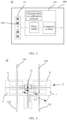
- the base station antenna system mainly includes an antenna 10, a feeder 02, a grounding apparatus 03, and the like.
- the antenna 10 is generally fastened on a holding pole 04, and downtilt of the antenna 10 may be adjusted by using an antenna adjustment bracket 05, to adjust a signal coverage area of the antenna 10 to some extent.
- the base station may further include a radio frequency processing unit 06 and a baseband processing unit.
- the radio frequency processing unit 06 may be configured to: perform frequency selection, amplification, and down-conversion processing on a signal received by the antenna 10, convert the signal into an intermediate frequency signal or a baseband signal, and send the intermediate frequency signal or the baseband signal to the baseband processing unit.
- the radio frequency processing unit 06 is configured to: perform up-conversion and amplification processing on the baseband processing unit or an intermediate frequency signal, convert the baseband processing unit or the intermediate frequency signal into a radio signal by using the antenna 10, and send the radio signal by using the antenna 10.
- the baseband processing unit may be connected to a feeding network of the antenna 10 through the radio frequency processing unit 06.
- the radio frequency processing unit may also be referred to as a remote radio unit (remote radio unit, RRU), and the baseband processing unit may also be referred to as a baseband unit (baseband unit, BBU).
- the radio frequency processing unit 06 and the antenna 10 may be integrally disposed.
- the baseband processing unit is located at a remote end of the antenna 10.
- both the radio frequency processing unit 06 and the baseband processing unit may be located at a remote end of the antenna 10.
- the radio frequency processing unit 06 and the baseband processing unit may be connected through the feeder 02.
- the antenna 10 used in the base station may include a housing 100, and a reflective plate 19 and a feeding network 110 that are located in the housing 100.
- a main function of the feeding network is to feed a signal to a radiating element 120 based on a specific amplitude and phase, or send, to the baseband processing unit of the base station based on a specific amplitude and phase, a radio signal received by the radiating element 120.
- the feeding network 110 may include at least one of a phase shifter, a combiner, a transmission or calibration network, a filter, or another component. Components and types of the feeding network 110 and functions that can be implemented by the feeding network 110 are not limited in this application.
- the antenna 10 may be further used in a plurality of other types of communication devices.
- An application scenario of the antenna 10 is not limited in this application.
- the housing 100 may also be referred to as a radome.
- the housing 100 In terms of electrical performance, the housing 100 has good electromagnetic wave penetrability. In this way, normal receiving and sending of an electromagnetic signal between the radiating element 120 and the outside are not affected.
- the housing 100 In terms of mechanical performance, the housing 100 has good force-bearing performance, anti-oxidation performance, and the like. In this way, the housing 100 can withstand corrosion of an external harsh environment.
- the radiating element 120 may also be referred to as an antenna element, and is a unit that forms a basic structure of the antenna.
- the radiating element 120 can effectively transmit or receive an electromagnetic wave.
- a plurality of radiating elements 120 may form an array for use.
- the antenna element may be classified into a single-polarization type, a dual-polarization type, and the like.
- a type of the antenna element may be properly selected based on an actual requirement.
- the reflective plate 19 is also referred to as a bottom plate.
- the reflective plate 19 generally has a front surface (or a reflective surface) and a back surface (a surface back away from the front surface).
- the front surface may provide an installation location for the radiating element 120, and can further effectively improve signal receiving and sending performance of the radiating element 120.
- the reflective plate 19 can further block and shield another electromagnetic signal from the back surface, to achieve a specific anti-interference effect for the radiating element 120.
- performance of the antenna 10 directly affects performance of the entire antenna system. Therefore, when the antenna 10 is configured, the performance of the antenna 10 needs to meet a corresponding requirement.
- Main parameters of the performance of the antenna 10 include a gain, a beam width, and the like. In some application scenarios, the antenna 10 needs to have a large gain.
- a structure like a director is configured in the antenna 10 to increase a gain of the antenna 10. However, this manner increases a height of a cross section of the antenna 10, and is not conducive to a miniaturization design of the antenna 10.
- embodiments of this application provide an antenna 10 that can narrow a beam width and increase a gain.
- the antenna 10 has a simple structure, is easy to be manufactured, and is conducive to reduce a height of a cross section and conducive to a miniaturization design.
- an antenna 10 includes a first radiating element 11 and a first conductive part.
- the first radiating element 11 is configured to transmit or receive a radio signal (namely, the electromagnetic wave described above, which is uniformly represented as the radio signal below).
- a radio signal namely, the electromagnetic wave described above, which is uniformly represented as the radio signal below.
- the first conductive part and the first radiating element 11 may be connected to a common ground by using the reflective plate 19.
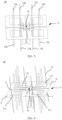
- the first radiating element 11 shown in FIG. 4 is a dual-polarization radiating element, and includes four radiating arms: a radiating arm a, a radiating arm b, a radiating arm c, and a radiating arm d.
- the radiating arm a and the radiating arm c are located in a polarization direction, and the radiating arm b and the radiating arm d are located in another polarization direction.
- Four first conductive parts are disposed: a first conductive part 12a, a first conductive part 12b, a first conductive part 12c, and a first conductive part 12d.
- the four first conductive parts are disposed in an annular shape around a center O of the first radiating element 11.
- a distance between the first conductive part and the center O of the first radiating element 11 is L1
- a maximum distance between the first radiating element 11 and the center O is L2
- the first conductive part is coupled to the first radiating element 11, so that a beam width of the first radiating element 11 is narrowed.
- coupling in this application is “electromagnetic coupling”, and means a phenomenon that two or more elements closely cooperate with each other and affect each other, and energy is transferred from one side to the other side through interaction.
- two first conductive parts may be disposed in each polarization direction of the first radiating element 11, and the two first conductive parts are disposed in an annular shape around the center of the first radiating element 11.
- the first radiating element 11 may be a single-polarization radiating element.
- the first radiating element 11 is the single-polarization radiating element, it is equivalent that the first radiating element 11 has only two arms shown in FIG. 4 .
- the first radiating element 11 may have a radiating arm a and a radiating arm c; or may have a radiating arm b and a radiating arm d.
- two first conductive parts may be configured, and the two first conductive parts are disposed in an annular shape around the center of the first radiating element 11.
- the center of the first radiating element 11 may be understood as a geometric center of the first radiating element 11.
- the first conductive parts are disposed in an annular shape around the center of the first radiating element 11 means that distances between all the first conductive parts and the center of the first radiating element 11 are the same.
- a plurality of first conductive parts may be disposed in an equidistant manner, that is, distances between two adjacent first conductive parts are the same, to ensure symmetry of a directivity pattern of a radiation field corresponding to the first radiating element 11.
- first conductive parts when the first conductive parts are disposed in an annular shape around the center of the first radiating element 11, a non-equidistant disposing manner may be used for implementation.
- first conductive parts and the first radiating element 11 may alternatively be disposed in a non-annular manner. For example, distances between all the first conductive parts and the center of the first radiating element 11 may be different. This is not limited in this application.
- first conductive parts configured for one first radiating element is not limited to the foregoing example. More generally, the quantity may be 2N, where N is a positive integer. To be specific, in another implementation, four, six, eight, ten, or more first conductive parts may be disposed in the first radiating element 11. A specific quantity of disposed first conductive parts is not limited in this application.
- a quantity of first conductive parts configured for one first radiating element may be further represented as 4N, where N is a positive integer.
- first conductive parts may be disposed in the first radiating element 11: a first conductive part 12a, a first conductive part 12b, a first conductive part 12c, a first conductive part 12d, a first conductive part 12e, a first conductive part 12f, a first conductive part 12g, and a first conductive part 12h.
- the eight first conductive parts are disposed in an annular shape around the center of the first radiating element 11.
- first conductive parts 12 may be disposed in the first radiating element 11 (where only one first conductive part 12 is marked in the figure), and the 12 first conductive parts 12 are disposed in an annular shape around the center of the first radiating element 11. It may be understood that a reference mark of the first conductive part in FIG. 6 is 12.
- different first conductive parts are distinguished in a form of letters (such as a and b) added after the reference mark 12.
- the first conductive part 12 may also be understood as the first conductive part 12a, 12b, 12c, or the like.
- first conductive parts 12 may be disposed in the first radiating element 11.
- a specific quantity of disposed first conductive parts 12 is not limited in this application.
- 2N first conductive parts 12 may be correspondingly disposed in one polarization direction of the first radiating element 11, and the 2N first conductive parts 12 may be disposed in an annular shape around the geometric center of the first radiating element 11, where N is a positive integer.
- the beam width of the first radiating element 11 can be effectively narrowed by configuring the first conductive part 12, and a height of a cross section of the antenna 10 is not significantly increased.
- the first conductive part 12 has a simple structure, and is easy to be processed. This is conducive to low-cost implementation, and is conducive to manufacturing and wide application. That the first conductive part 12 can narrow the beam width of the first radiating element 11 is specifically as follows: When the first radiating element 11 transmits the radio signal, an induced current is generated on the first conductive part 12. In addition, the induced current can further enable the first conductive part 12 to generate a radio signal.
- a phase of the induced current and a phase of a current on the first radiating element 11 are the same, a phase of the radio signal generated by the first conductive part 12 and a phase of the radio signal generated by the first radiating element 11 are the same, and the two signals are superposed to narrow the beam width.
- the radiating arm a and the radiating arm c on the first radiating element 11 transmit a radio signal
- an induced current is generated on the conductive part 12a and the conductive part 12c.
- a phase of the radio signal generated by the radiating arm a and the radiating arm c and a phase of the radio signal generated by the conductive part 12a and the conductive part 12c are the same, and the two signals are superposed to narrow the beam width.
- first radiating element 11 there may be various structure shapes of the first radiating element 11.
- an edge profile of the first radiating element 11 is approximately a square.
- the first radiating element 11 may be of another structure type such as an ellipse, a circle, or a rectangle. This is not limited in this application.
- first conductive part 12 there may be various relative locations between the first conductive part 12 and the first radiating element 11.
- each of the radiating arm a, the radiating arm b, the radiating arm c, and the radiating arm d of the first radiating element 11 is provided with one through hole 111, and each through hole 111 is penetrated by three first conductive parts 12.
- the radiating element may be provided with a through hole 111 for the first conductive part 12 to penetrate, to avoid interference between the first conductive part 12 and the radiating element.
- each through hole 111 may be penetrated by only one first conductive part 12, or may be simultaneously penetrated by a plurality of first conductive parts 12. This is not specifically limited in this application.
- the first conductive part 12 may be disposed close to an edge of the first radiating element 11.
- the relative location between the first conductive part 12 and the radiating element may be properly adjusted based on an actual requirement. This is not limited in this application.
- a specific value of L1 may be properly set based on an actual situation.
- L1 may be less than or equal to 0.1 times an operating wavelength of the first radiating element 11.
- the distance between the first conductive part and the center of the first radiating element 11 is properly adjusted, so that a coupling effect between the first conductive part and the first radiating element 11 can be effectively improved, thereby effectively narrowing the beam width of the first radiating element 11 and increasing a gain of the first radiating element 11.
- the operating wavelength of the first radiating element 11 is a wavelength corresponding to a frequency of the radio signal transmitted or received by the first radiating element 11.
- a length of the first conductive part may also be properly adjusted based on an actual requirement.
- the first conductive part is in a linear shape, and the length of the first conductive part may be greater than or equal to 0.25 times the operating wavelength of the first radiating element 11.
- the length of the first conductive part may be 0.26 times, 0.27 times, 0.28 times, or the like the operating wavelength of the first radiating element 11. This is not specifically limited in this application.
- lengths of the plurality of first conductive parts may be the same or may be different. This is not specifically limited in this application.
- first conductive part when the first conductive part is disposed, there may be various shapes of the first conductive part.
- the first conductive part 12 is of a linear shape, or referred to as a strip shape.
- the first conductive part 12 may be manufactured by using a metal (for example, copper or aluminum) or another non-metallic material with good conductivity. During manufacturing, preparation processes such as die casting and cutting may be used for manufacturing.
- the first conductive part 12 may be a printed circuit board.
- the first conductive part 12 may be manufactured by using another conductive material or another preparation process. This is not limited in this application.
- a horizontal coordinate represents an operating frequency in a unit of GHz
- a vertical coordinate represents a beam width in a unit of degree (deg).
- Dashed lines S1 to S4 each represent a simulation curve of the beam width that is of the first radiating element 11 and that changes with the operating frequency when no first conductive part 12 is disposed.
- Solid lines L1 to L4 each represent a simulation curve of the beam width that is of the first radiating element 11 and that changes with the operating frequency after the first conductive part 12 is disposed.
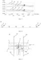
- the antenna 10 may further include a second radiating element 13.
- the operating frequency of the first radiating element 11 may be greater than an operating frequency of the second radiating element 13. It may be understood that, a plurality of radiating elements with different operating frequencies are configured in the antenna 10, so that a bandwidth of the antenna 10 can be effectively increased.
- operating frequencies of the radiating elements are within a frequency band range, instead of being a specific frequency band. Therefore, that the operating frequency of the first radiating element 11 is greater than the operating frequency of the second radiating element 13 may also be understood as that a maximum operating frequency of the first radiating element 11 is greater than a maximum operating frequency of the second radiating element 13.
- a second conductive part 14 may be disposed in the second radiating element 13, to narrow the beam width of the antenna 10 and increase the gain.
- first radiating element 11 and the second radiating element 13 may be understood as two radiating elements with different operating frequencies.
- first conductive part 12 is a conductive part that is disposed in correspondence to the first radiating element 11
- second conductive part 14 is a conductive part that is disposed in correspondence to the second radiating element 12.
- a manner of disposing the second conductive part 14 relative to the second radiating element 13 may be the same as or similar to a manner of disposing the first conductive part 12 relative to the first radiating element 11.
- four second conductive parts are disposed: a second conductive part 14a, a second conductive part 14b, a second conductive part 14c, and a second conductive part 14d.
- the four second conductive parts are disposed in an annular shape around a center O of the second radiating element 13.
- a distance between the second conductive part and the center O of the second radiating element 13 is L3, a maximum distance between the second radiating element 13 and the center O is L4, and L3 ⁇ L4.
- the second conductive part is coupled to the second radiating element 13, so that a beam width of the second radiating element 13 is narrowed.
- the second conductive part 14 and the first conductive part 12 may have a same structure or a roughly same structure.
- embodiments of this application further provides a data simulation comparison diagram.
- a horizontal coordinate represents an operating frequency in a unit of GHz
- a vertical coordinate represents a beam width in a unit of deg.
- Dashed lines S 1 to S4 each represent a simulation curve of the beam width that is of the second radiating element 13 and that changes with the operating frequency when no second conductive part 14 is disposed.
- Solid lines L1 to L4 each represent a simulation curve of the beam width that is of the second radiating element 13 and that changes with the operating frequency after the second conductive part 14 is disposed.
- the first radiating element 11 when the second conductive part 14 is disposed for the second radiating element 13, when generating the radio signal, the first radiating element 11 generates an induced current in the second conductive part 14. Because a phase of the induced current is opposite to a phase of a current in the first radiating element 11, signal transmission efficiency of the first radiating element 11 is reduced, and the signal of the first radiating element 11 is interfered. Therefore, during actual application, a filtering structure may be disposed in the second conductive part 14, to suppress the induced current in the second conductive part 14, thereby reducing interference caused by the second conductive part 14 to signal transmission of the first radiating element 11.
- a filtering structure 141 is disposed in the second conductive part 14, so that an induced current generated in the second conductive part 14 by a radio signal, with a high frequency band, generated by the first radiating element 11 can be suppressed, thereby improving signal transmission efficiency and transmission quality of the first radiating element 11.
- the filtering structure 141 is specifically of an inductor structure, and a high-frequency current flowing through the second conductive part 14 can be suppressed by using characteristics of low-frequency pass-through and high-frequency resistance of the inductor structure.
- the inductor structure may suppress the induced current generated in the second conductive part 14 by the radio signal generated by the first radiating element 11.
- the filtering structure 141 may be of the inductor structure, or may be another device, for example, a filter, that can suppress the high-frequency current.
- the filtering structure 141 is of the inductor structure.
- the second conductive part 14 may be bent to form the inductor structure.
- the high-frequency current can be suppressed by using the characteristics of low-frequency pass-through and high-frequency resistance of the inductor structure.
- a horizontal coordinate represents an operating frequency in a unit of GHz
- a vertical coordinate represents a gain in a unit of dB.
- Dashed lines S 1 and S2 each represent a simulation curve of the gain that is of the first radiating element 11 and that changes with the operating frequency when no second conductive part 14 is disposed.
- Solid lines L1 and L2 each represent a simulation curve of the gain that is of the first radiating element 11 and that changes with the operating frequency after the second conductive part 14 having the filtering structure is disposed.
- the filtering structure 141 there may be various structure forms of the filtering structure 141.
- the filtering structure 141 may alternatively be a fork structure.
- the two fork structures are disposed, and the two fork structures are symmetrically disposed.
- one fork structure may be disposed, or three or more fork structures may be disposed. This is not limited in this application.
- the filtering structure 141 may include a bent structure and a fork structure.
- the filtering structure 141 may include a wide-narrow connection structure.
- the filtering structure 141 may include a wide part 1411 with a large cross section and a narrow part 1412 with a small cross section. The wide part 1411 and the narrow part 1412 are sequentially connected, to form the inductor structure, thereby suppressing the high-frequency current.
- the filtering structure 141 may include one of the wide-narrow connection structure, the fork structure, or the bent structure, or a combination of at least two of the structures.
- the second conductive part 14 may include another type of filtering structure 141 that can suppress a current with a high frequency band. This is not specifically limited in this application.
- two or more radiating elements may be disposed in the antenna 10.
- a conductive part for example, the first conductive part 12 or the second conductive part 14 mentioned above
- conductive parts are disposed in some radiating elements.
- operating frequencies of all the radiating elements may be the same, or an operating frequency of at least one radiating element is different from operating frequencies of other radiating elements.
- a filtering structure that is the same as or roughly the same as that in the second conductive part 14 may also be disposed. This is not limited in this application.
- the antenna is also developing toward miniaturization and high integrity.
- the antenna may include a plurality of radiating elements, and the plurality of radiating elements operating in different frequency bands need to be closely arranged to reduce a size of an antenna unit.
- the plurality of radiating elements are closely arranged, a clear coupling phenomenon easily occurs between the radiating elements operating in different frequency bands, and communication quality of the entire antenna is significantly affected.
- the clear coupling phenomenon occurs between the radiating elements operating in different frequency bands is also referred to as common-mode resonance between the different radiating elements in the antenna.
- a tuning circuit is introduced to suppress common-mode resonance.
- using the tuning circuit makes a structure of the antenna become complex, and increases processing difficulty and matching difficulty. Therefore, this is not conducive to actual application.
- An operating frequency band of a radiating element is determined by a structure and a boundary of the radiating element.
- a size of a low-frequency radiating element is large, and a size of a high-frequency radiating element is small.
- a radio signal radiated by the high-frequency radiating element easily generates common-mode resonance with the low-frequency radiating element, affecting normal operation and radiation performance of the low-frequency radiating element. From a perspective of a directivity pattern, a directivity pattern of the low-frequency radiating element is distorted.
- the antenna 10 may further include a third conductive part 15.
- the third conductive part 15 and a radiating element operating in a high frequency band may be connected to a common ground, and is configured to suppress common-mode resonance generated by a radio signal with a high frequency in a radiating element operating in a low frequency band.
- the operating frequency of the first radiating element 11 is greater than the operating frequency of the second radiating element 13.
- the third conductive part 15 is disposed at the center of the first radiating element 11, and the third conductive part 15 and the first radiating element 11 are connected to a common ground.
- the third conductive part 14 is coupled to the first radiating element 11, and is configured to suppress common-mode resonance generated by the first radiating element 11 in a frequency band in which the second radiating element 13 is located. For example, when the second radiating element 13 generates a radio signal, the first radiating element 11 is coupled to the second radiating element 13. Therefore, an induced current is generated on the first radiating element 11, and the induced current deteriorates performance of the second radiating element 13.
- the third conductive part 15 is disposed at the center of the first radiating element 11, when the second radiating element 13 generates the radio signal, the first radiating element 11 and the third conductive part 15 induce induced currents with opposite phases, and the two circuits cancel each other, to reduce impact on the second radiating element 13.
- the third conductive part 15 may alternatively be disposed slightly away from the center of the first radiating element 11. Alternatively, it may be understood that the third conductive part 15 may be located at the center of the first radiating element 11 or in an area near the center.
- a length of the third conductive part 15 may also be properly adjusted based on an actual requirement.
- the length of the third conductive part 15 may be greater than or equal to 0.25 times the operating wavelength of the first radiating element 11.
- the third conductive part 15 is slightly greater than 0.25 times the operating wavelength of the first radiating element 11, the third conductive part 15 can be better coupled to the first radiating element 11, to effectively suppress the high-frequency current in the first radiating element 11.
- the length of the third conductive part 15 may be 0.26 times, 0.27 times, 0.28 times, or the like the operating wavelength of the first radiating element 11. This is not specifically limited in this application.
- the third conductive part 15 may be of a long strip structure, and the third conductive part 15 may be manufactured by using a metal (for example, copper or aluminum) or another non-metallic material with good conductivity. During manufacturing, preparation processes such as die casting and cutting may be used for manufacturing. Alternatively, the third conductive part 15 may be a printed circuit board.
- the third conductive part 15 may be manufactured by using another conductive material or another preparation process. This is not limited in this application.
- the first radiating element 11 may further perform feeding by using a balun 16.
- a main function of the balun 16 is to convert and match an electrical signal that is relatively balanced with a reference ground and an electrical signal that is relatively unbalanced with the reference ground, to improve a matching degree between the first radiating element 11 and a feeding network, thereby improving signal transmission quality of the first radiating element 11.
- balun 16 may be disposed by using a currently conventional type, and details are not described herein.
- the third conductive part 15 may be further electrically connected to the balun 16, so that a phase of a current in the third conductive part 15 is opposite to a phase of a current in the balun 16, and the currents can cancel each other, to effectively suppress common-mode resonance.
- the first radiating element 11 may be equipped with a director 17 to increase the gain of the first radiating element 11. It may be understood that, during specific implementation, a specific parameter, a type, and a disposing location of the director 17 may be properly adjusted based on an actual requirement. This is not specifically limited in this application.
- both the first conductive part 12 and the third conductive part 15 may be disposed in the first radiating element 11.
- the third conductive part 15 and the first radiating element 11 may be connected to a common ground in a plurality of manners.
- the third conductive part 15 and the first radiating element 11 are connected to a common ground may be implemented by disposing an additional common ground plate 18.
- the common ground plate 18 may be a metal plate or a printed circuit board, or may be of another type of conductive structure. This is not limited in this application.
- the antenna 10 may include a reflective plate 19.
- the reflective plate 19 generally has a front surface (namely, a reflective surface) and a back surface (a surface back away from the front surface).
- the front surface may provide installation locations for the radiating elements (for example, the first radiating element 11 and the second radiating element 13), and can further effectively improve signal receiving and sending performance of the radiating elements.
- the reflective plate 19 can further block and shield another electromagnetic signal from the back surface, to achieve a specific anti-interference effect for the radiating elements.
- the reflective plate 19 is generally manufactured by using a conductive material like a metal. Therefore, when the third conductive part 15 and the first radiating element 11 are connected to a common ground, both the third conductive part 15 and the first radiating element 11 may be electrically connected to the reflective plate 19.
Landscapes
- Physics & Mathematics (AREA)
- Electromagnetism (AREA)
- Engineering & Computer Science (AREA)
- Computer Networks & Wireless Communication (AREA)
- Variable-Direction Aerials And Aerial Arrays (AREA)
Applications Claiming Priority (2)
| Application Number | Priority Date | Filing Date | Title |
|---|---|---|---|
| CN202111238180.3A CN116014419B (zh) | 2021-10-22 | 2021-10-22 | 一种天线和通信设备 |
| PCT/CN2022/121391 WO2023065981A1 (zh) | 2021-10-22 | 2022-09-26 | 一种天线和通信设备 |
Publications (2)
| Publication Number | Publication Date |
|---|---|
| EP4421987A1 true EP4421987A1 (de) | 2024-08-28 |
| EP4421987A4 EP4421987A4 (de) | 2025-02-26 |
Family
ID=86030440
Family Applications (1)
| Application Number | Title | Priority Date | Filing Date |
|---|---|---|---|
| EP22882592.3A Pending EP4421987A4 (de) | 2021-10-22 | 2022-09-26 | Antenne und kommunikationsvorrichtung |
Country Status (4)
| Country | Link |
|---|---|
| US (1) | US20240275065A1 (de) |
| EP (1) | EP4421987A4 (de) |
| CN (1) | CN116014419B (de) |
| WO (1) | WO2023065981A1 (de) |
Families Citing this family (3)
| Publication number | Priority date | Publication date | Assignee | Title |
|---|---|---|---|---|
| WO2025190476A1 (en) | 2024-03-12 | 2025-09-18 | Telefonaktiebolaget Lm Ericsson (Publ) | Antenna, mobile communication base station and user device |
| US20250357660A1 (en) * | 2024-05-16 | 2025-11-20 | Outdoor Wireless Networks LLC | Base station antennas with low-band arrays having low-band radiating elements having parasitic monopole elements |
| WO2026061625A1 (en) * | 2024-09-20 | 2026-03-26 | Huawei Technologies Co., Ltd. | A multi-band antenna with a broadband improved director |
Family Cites Families (11)
| Publication number | Priority date | Publication date | Assignee | Title |
|---|---|---|---|---|
| FR2808128B1 (fr) * | 2000-04-20 | 2002-07-19 | Cit Alcatel | Antenne monolithique a polarisation croisee |
| US8373597B2 (en) * | 2006-08-09 | 2013-02-12 | Spx Corporation | High-power-capable circularly polarized patch antenna apparatus and method |
| CN101170212A (zh) * | 2007-11-12 | 2008-04-30 | 杭州电子科技大学 | 共面波导单点馈电背腔圆极化天线 |
| JP5735591B2 (ja) * | 2013-08-02 | 2015-06-17 | 日本電業工作株式会社 | アンテナ及びセクタアンテナ |
| CN106025573B (zh) * | 2015-03-31 | 2019-03-26 | 启碁科技股份有限公司 | 天线及复合天线 |
| CN105098376B (zh) * | 2015-07-02 | 2019-01-25 | 华为技术有限公司 | 天线振子及其制造方法、安装天线装置的方法和天线装置 |
| CN106654557B (zh) * | 2016-12-16 | 2023-09-29 | 淮阴工学院 | 一种双频点宽频带偶极子天线 |
| US10770803B2 (en) * | 2017-05-03 | 2020-09-08 | Commscope Technologies Llc | Multi-band base station antennas having crossed-dipole radiating elements with generally oval or rectangularly shaped dipole arms and/or common mode resonance reduction filters |
| CN107359418B (zh) * | 2017-05-31 | 2019-11-29 | 上海华为技术有限公司 | 一种多频天线系统及控制多频天线系统内异频干扰的方法 |
| GB2578388A (en) * | 2017-06-20 | 2020-05-06 | Cubic Corp | Broadband antenna array |
| EP4399766A4 (de) * | 2021-09-08 | 2025-06-25 | Outdoor Wireless Networks LLC | Breitbandige entkopplungsstrahlungselemente und basisstationsantennen mit solchen strahlungselementen |
-
2021
- 2021-10-22 CN CN202111238180.3A patent/CN116014419B/zh active Active
-
2022
- 2022-09-26 EP EP22882592.3A patent/EP4421987A4/de active Pending
- 2022-09-26 WO PCT/CN2022/121391 patent/WO2023065981A1/zh not_active Ceased
-
2024
- 2024-04-22 US US18/642,388 patent/US20240275065A1/en active Pending
Also Published As
| Publication number | Publication date |
|---|---|
| US20240275065A1 (en) | 2024-08-15 |
| EP4421987A4 (de) | 2025-02-26 |
| CN116014419A (zh) | 2023-04-25 |
| CN116014419B (zh) | 2026-03-24 |
| WO2023065981A1 (zh) | 2023-04-27 |
Similar Documents
| Publication | Publication Date | Title |
|---|---|---|
| US20240275065A1 (en) | Antenna and communication device | |
| EP4386983A1 (de) | Antennensystem und basisstationsantennenspeisungssystem | |
| US20240339749A1 (en) | Antenna system and communication device | |
| EP4451461A1 (de) | Antennensystem und basisstationsantennenzuführsystem | |
| US20230335902A1 (en) | Multi-band antenna and communication device | |
| EP4576433A1 (de) | Basisstationsantenne und basisstation | |
| CN113904102B (zh) | 一种天线及通信设备 | |
| US20240291138A1 (en) | Antenna and communication device | |
| EP4576429A1 (de) | Antennenstruktur, antenne und basisstation | |
| US20250174886A1 (en) | Antenna and communication device | |
| US20250379363A1 (en) | Antenna element, antenna system, and communication device | |
| US20240243470A1 (en) | Antenna and base station antenna feeder system | |
| CN117996421B (zh) | 一种天线系统及基站 | |
| CN116266673A (zh) | 一种天线和通信设备 | |
| US20250055178A1 (en) | Base station antenna and base station | |
| US20250279588A1 (en) | Antenna and communication device | |
| CN116130904B (zh) | 移相器、天线及基站天馈系统 | |
| CN116073113B (zh) | 一种多频天线及通信设备 | |
| EP4572011A1 (de) | Antenne und kommunikationsvorrichtung | |
| US20250316907A1 (en) | Feeding apparatus, antenna apparatus, and communication device | |
| US20260045688A1 (en) | Antenna apparatus, antenna system, and communication device | |
| EP4513680A1 (de) | Antenne, kommunikationsvorrichtung und kommunikationssystem | |
| WO2025026075A1 (zh) | 一种天线振子、天线及通信设备 | |
| CN116315590A (zh) | 一种天线结构、基站天线及基站 | |
| WO2025119284A1 (zh) | 一种天线阵列结构、天线和通信设备 |
Legal Events
| Date | Code | Title | Description |
|---|---|---|---|
| STAA | Information on the status of an ep patent application or granted ep patent |
Free format text: STATUS: THE INTERNATIONAL PUBLICATION HAS BEEN MADE |
|
| PUAI | Public reference made under article 153(3) epc to a published international application that has entered the european phase |
Free format text: ORIGINAL CODE: 0009012 |
|
| STAA | Information on the status of an ep patent application or granted ep patent |
Free format text: STATUS: REQUEST FOR EXAMINATION WAS MADE |
|
| 17P | Request for examination filed |
Effective date: 20240522 |
|
| AK | Designated contracting states |
Kind code of ref document: A1 Designated state(s): AL AT BE BG CH CY CZ DE DK EE ES FI FR GB GR HR HU IE IS IT LI LT LU LV MC MK MT NL NO PL PT RO RS SE SI SK SM TR |
|
| REG | Reference to a national code |
Ref country code: DE Ref legal event code: R079 Free format text: PREVIOUS MAIN CLASS: H01Q0001380000 Ipc: H01Q0005420000 |
|
| DAV | Request for validation of the european patent (deleted) | ||
| DAX | Request for extension of the european patent (deleted) | ||
| A4 | Supplementary search report drawn up and despatched |
Effective date: 20250129 |
|
| RIC1 | Information provided on ipc code assigned before grant |
Ipc: H01Q 21/26 20060101ALI20250123BHEP Ipc: H01Q 1/24 20060101ALI20250123BHEP Ipc: H01Q 25/00 20060101ALI20250123BHEP Ipc: H01Q 19/30 20060101ALI20250123BHEP Ipc: H01Q 5/42 20150101AFI20250123BHEP |