EP4422011A1 - Système de stockage d'énergie distribué et système d'alimentation en énergie distribué - Google Patents
Système de stockage d'énergie distribué et système d'alimentation en énergie distribué Download PDFInfo
- Publication number
- EP4422011A1 EP4422011A1 EP23158565.4A EP23158565A EP4422011A1 EP 4422011 A1 EP4422011 A1 EP 4422011A1 EP 23158565 A EP23158565 A EP 23158565A EP 4422011 A1 EP4422011 A1 EP 4422011A1
- Authority
- EP
- European Patent Office
- Prior art keywords
- energy
- load storage
- network
- peak load
- storage device
- Prior art date
- Legal status (The legal status is an assumption and is not a legal conclusion. Google has not performed a legal analysis and makes no representation as to the accuracy of the status listed.)
- Pending
Links
Images

Classifications
-
- H—ELECTRICITY
- H02—GENERATION; CONVERSION OR DISTRIBUTION OF ELECTRIC POWER
- H02J—ELECTRIC POWER NETWORKS; CIRCUIT ARRANGEMENTS OR SYSTEMS FOR SUPPLYING OR DISTRIBUTING ELECTRIC POWER; SYSTEMS FOR STORING ELECTRIC ENERGY
- H02J4/00—Circuit arrangements for mains or distribution networks not specified as AC or DC; Circuit arrangements for mains or distribution networks combining AC and DC sections or sub-networks
-
- H—ELECTRICITY
- H02—GENERATION; CONVERSION OR DISTRIBUTION OF ELECTRIC POWER
- H02J—ELECTRIC POWER NETWORKS; CIRCUIT ARRANGEMENTS OR SYSTEMS FOR SUPPLYING OR DISTRIBUTING ELECTRIC POWER; SYSTEMS FOR STORING ELECTRIC ENERGY
- H02J1/00—Circuit arrangements for DC mains or DC distribution networks
- H02J1/04—Current-controlled supply systems, e.g. constant-current supply systems
-
- H—ELECTRICITY
- H02—GENERATION; CONVERSION OR DISTRIBUTION OF ELECTRIC POWER
- H02J—ELECTRIC POWER NETWORKS; CIRCUIT ARRANGEMENTS OR SYSTEMS FOR SUPPLYING OR DISTRIBUTING ELECTRIC POWER; SYSTEMS FOR STORING ELECTRIC ENERGY
- H02J3/00—Circuit arrangements for AC mains or AC distribution networks
- H02J3/28—Arrangements for balancing of the load in networks by storage of energy
- H02J3/32—Arrangements for balancing of the load in networks by storage of energy using batteries or super capacitors with converting means
-
- H—ELECTRICITY
- H02—GENERATION; CONVERSION OR DISTRIBUTION OF ELECTRIC POWER
- H02J—ELECTRIC POWER NETWORKS; CIRCUIT ARRANGEMENTS OR SYSTEMS FOR SUPPLYING OR DISTRIBUTING ELECTRIC POWER; SYSTEMS FOR STORING ELECTRIC ENERGY
- H02J3/00—Circuit arrangements for AC mains or AC distribution networks
- H02J3/38—Arrangements for feeding a single network from two or more generators or sources in parallel; Arrangements for feeding already energised networks from additional generators or sources in parallel
- H02J3/381—Dispersed generators
-
- H—ELECTRICITY
- H02—GENERATION; CONVERSION OR DISTRIBUTION OF ELECTRIC POWER
- H02J—ELECTRIC POWER NETWORKS; CIRCUIT ARRANGEMENTS OR SYSTEMS FOR SUPPLYING OR DISTRIBUTING ELECTRIC POWER; SYSTEMS FOR STORING ELECTRIC ENERGY
- H02J7/00—Circuit arrangements for charging or discharging batteries or for supplying loads from batteries
- H02J7/34—Parallel operation in networks using both storage and other DC sources, e.g. providing buffering
- H02J7/342—The other DC source being a battery actively interacting with the first one, i.e. battery to battery charging
-
- H—ELECTRICITY
- H02—GENERATION; CONVERSION OR DISTRIBUTION OF ELECTRIC POWER
- H02J—ELECTRIC POWER NETWORKS; CIRCUIT ARRANGEMENTS OR SYSTEMS FOR SUPPLYING OR DISTRIBUTING ELECTRIC POWER; SYSTEMS FOR STORING ELECTRIC ENERGY
- H02J7/00—Circuit arrangements for charging or discharging batteries or for supplying loads from batteries
- H02J7/485—Circuit arrangements for charging or discharging batteries or for supplying loads from batteries with provisions for charging different types of batteries
-
- H—ELECTRICITY
- H02—GENERATION; CONVERSION OR DISTRIBUTION OF ELECTRIC POWER
- H02J—ELECTRIC POWER NETWORKS; CIRCUIT ARRANGEMENTS OR SYSTEMS FOR SUPPLYING OR DISTRIBUTING ELECTRIC POWER; SYSTEMS FOR STORING ELECTRIC ENERGY
- H02J7/00—Circuit arrangements for charging or discharging batteries or for supplying loads from batteries
- H02J7/50—Circuit arrangements for charging or discharging batteries or for supplying loads from batteries acting upon multiple batteries simultaneously or sequentially
-
- H—ELECTRICITY
- H02—GENERATION; CONVERSION OR DISTRIBUTION OF ELECTRIC POWER
- H02J—ELECTRIC POWER NETWORKS; CIRCUIT ARRANGEMENTS OR SYSTEMS FOR SUPPLYING OR DISTRIBUTING ELECTRIC POWER; SYSTEMS FOR STORING ELECTRIC ENERGY
- H02J7/00—Circuit arrangements for charging or discharging batteries or for supplying loads from batteries
- H02J7/80—Circuit arrangements for charging or discharging batteries or for supplying loads from batteries including monitoring or indicating arrangements
- H02J7/82—Control of state of charge [SOC]
Definitions
- the invention relates to a decentralized energy storage system for an energy network that is self-sufficient or connected to a supply network.
- the invention also relates to a decentralized energy supply system with a decentralized energy storage system.
- Electrode and lithium-ion batteries are currently the most commonly used battery technologies for storing large amounts of energy.
- alternative battery technologies such as saltwater batteries (also known as sodium-ion batteries) or the zebra battery (also known as sodium nickel chloride batteries) are becoming increasingly popular. These technologies in particular can only be charged and discharged relatively slowly.
- this technology offers great advantages in terms of cost, safety and environmental compatibility compared to established technologies.
- the properties of the storage are not optimally designed for the respective energy generation situation and/or energy consumption. It can happen that required peak loads cannot be provided completely or quickly enough and/or existing electrical energy cannot be stored quickly enough. As a result, energy is lost.
- the aim of this invention is to enable optimized energy storage through the combination of different storage technologies and their control.
- a decentralized energy storage system for an energy network that is self-sufficient or connected to a supply network, with at least one first peak load storage device that is arranged at a first storage location.
- the energy network can therefore be designed autonomously or connected to the supply network.
- the energy storage system has at least one second peak load storage device that is arranged at a second storage location.
- the energy storage system has at least one base load storage device.
- the at least one base load storage device and the first peak load storage device are provided at a consumer of the energy network.
- the base load storage device is based on a different storage technology than the peak load storage devices.
- the energy storage system comprises a control unit that is set up to control charging and/or discharging cycles of the peak load storage devices and the at least one base load storage device.
- the peak load storage devices and the at least one base load storage device are electrically connected to one another. At least the first storage location and the second storage location are spaced apart from one another.
- Consumers can be, for example, businesses, industrial plants and/or industrial sites.
- the consumer is therefore, for example, a customer.
- the consumer is not an electrical consumer.
- the consumer can have several electrical consumers.
- the energy network can, for example, be an overall network to which several consumers and energy producers such as solar systems or wind turbines are connected.
- the overall network is preferably connected to the public supply network.
- the energy network is a low-voltage network, which is provided, for example, within a company or a building technology system.
- the basic idea of the invention is to combine different storage technologies in order to make use of their individual advantages.
- the different storage devices are cleverly distributed in the energy network. This means that the right amount of energy can be made available from a nearby storage device at the desired location, in particular directly at the consumer's location, when required.
- the short distances between the consumer, in particular the electrical consumers at the consumer's site, and the base load storage facility and the first peak load storage facility prevent unnecessary power losses when transporting energy in the energy network.
- the corresponding lines are therefore designed to be short so that line losses can be minimized.
- the cables can be designed with a smaller cross-section, as the current flow can be kept constant over large parts of the network.
- the current carrying capacity for the peak load only needs to be taken into account up to the next peak load storage facility. This saves material and therefore also costs.
- a further consumer can be supplied by the second peak load storage unit, which is arranged at a distance from the first peak load storage unit.
- the second peak load storage unit can therefore be provided for a different consumer.
- the first and second peak load storage units are arranged at a distance from one another at the same consumer, for example within a company, in order to provide energy for different operating systems as required.
- the at least one base load storage device has a C-rate that is lower than a C-rate of the peak load storage devices, in particular lower by a factor of 10.
- the C-rate indicates how quickly a storage device can be charged and/or discharged.
- the storage devices of different storage technologies often have very different C-rates.
- storage devices that offer advantages from an environmental, risk and/or cost perspective often have a rather low C-rate.
- battery technologies e.g. lithium-ion accumulators, which currently have high C-rates of up to 3 and can therefore be charged or discharged relatively quickly.
- the positive properties of the two technologies can be combined.
- a storage system can be created that is tailored to specific requirements and that can provide energy quickly enough while also offering environmental and cost benefits, particularly improving efficiency.
- At least one of the peak load storage units and the base load storage unit are connected to one another via a supply line that is separate from the energy network and via which the corresponding peak load storage unit can be charged from the base load storage unit.
- the separate supply line means that the resources of the energy network do not have to be used for charging.
- the control is correspondingly simple and error-free.
- the supply line that is separate from the power grid can be a redundant line to the power grid.
- This energy exchange can also take place the other way round, for example when there is a lot of energy available and little energy is consumed or required by the consumer, i.e. by the consumer's electrical consumers. For example, this can be the case with an associated solar system when it is very sunny, such as during the midday sun.
- the base load storage and the peak load storage can also be referred to as base energy storage and peak energy storage, respectively, since the storage units not only serve to cover the corresponding load, but also (temporarily) store energy.
- the energy storage system can also be designed to transfer electrical energy from the at least one base load storage device to at least one of the peak load storage devices, in particular wherein the transfer preferably takes place using direct current.
- the direct current transfer can avoid conversion into alternating current and subsequent reconversion. Accordingly, no conversion losses occur.
- control unit is set up to control at least one remaining storage unit in the event of a failure of one of the storage units in such a way that compensation energy is retrieved from the remaining storage unit.
- the failed storage unit can be repaired or replaced during normal operation of the energy storage system, in particular without having to interrupt the energy supply.
- control unit is set up to take environmental conditions into account when controlling the charging and/or discharging cycles of the peak load storage units and at least one base load storage unit.
- Environmental aspects, hazards such as fire and explosion, current energy costs and/or availability can be taken into account in order to ensure a safe and cost-optimized energy supply.
- the decentralized energy storage system has a direct current network or at least two sub-networks, one of which is a direct current network and the other an alternating current network.
- direct current generated for example from a solar system, can be fed directly to the storage units, i.e. without being converted into alternating current.
- Direct current or alternating current can then be fed from the storage units to the consumers.
- a particularly suitable application is implementation in a DC low-voltage energy network.
- This can be a supply network itself or a DC low-voltage network connected to a supply network.
- a further aspect of the invention provides that at least the base load storage and the first peak load storage are connected downstream of a transfer point in relation to the supply network.
- the energy network with the storage units can be connected to the supply network via the transfer point. Excess energy can be delivered to the supply network, i.e. fed into the supply network. On the other hand, additionally required energy can also be obtained or taken from the supply network. An electricity meter can be provided at the transfer point.
- a decentralized energy supply system comprising a decentralized energy storage system according to the invention, an energy network connected to a supply network and a plurality of consumers which are arranged at different locations within the energy network at a distance from one another, as well as a plurality of producers which are arranged at different locations at a distance from one another.
- a consumer is understood to be a device that converts electrical energy into another form of energy, such as kinetic energy, thermal energy or chemical energy. This can be used to direct or indirect use.
- a consumer can be located within a company (i.e. at a customer's premises) together with many other consumers. The consumer can also be referred to as an electrical consumer.
- the first peak load storage unit is directly electrically connected to one of the consumers. This means that, when required, electrical energy can be transmitted from the peak load storage unit to the connected consumer with minimal loss.
- the first peak load storage unit has a storage capacity that corresponds to a peak energy consumption of the directly connected consumer. This means that all of the energy required by the consumer can be provided from the first peak load storage unit alone.
- the peak load storage units are distributed throughout the energy network and that the energy network is designed to a predefined design value that depends on the average consumption in the energy network, since the peak load storage units distributed throughout the energy network provide the energy for peak loads. In other words, the entire energy network does not have to be designed to transmit electrical energy during peak loads, since this energy can be provided locally by the peak load storage units.
- the energy supply system is designed for a current below a maximum current, in particular where the energy network is set up to be operated with a constant current.
- the maximum current is the maximum current that can occur in the energy supply system, in particular between a consumer and a directly connected peak load storage device.
- this maximum current only occurs locally, the entire energy network does not have to be designed for this in an expensive and complex manner.
- the decentralized energy supply system comprises at least part of the supply network.
- the energy producers and/or consumers can be located at least partially in that part of the supply network. This means that an existing supply network infrastructure can be used. It is not necessary to implement a complex energy network that connects all energy producers, consumers and storage facilities.
- a further aspect of the invention provides that at least the second peak load storage device or a second base load storage device is directly connected to one of the energy generators, wherein the respective energy generator is designed to store excess energy generated directly in the second peak load storage device or in the second base load storage device.
- the respective energy generator is designed to store excess energy generated directly in the second peak load storage device or in the second base load storage device.
- FIG. 1 shows a first embodiment of a decentralized energy supply system 10.
- This comprises a decentralized energy storage system 12 according to the invention and an energy network 14 which is connected to a supply network 16, for example a public supply network.
- the decentralized energy supply system 10 comprises a plurality of energy generators 18, for example a solar power plant 20, a wind power plant 22, a gas turbine 24 and/or a hydroelectric power plant 26, which are arranged at different locations at a distance from one another.
- energy generators 18 for example a solar power plant 20, a wind power plant 22, a gas turbine 24 and/or a hydroelectric power plant 26, which are arranged at different locations at a distance from one another.
- the type and number of the energy generators 18 mentioned are not to be understood as limiting.
- a plurality of consumers 28 of the energy network 14 are also arranged, for example an industrial plant 30 and building services 32.
- the consumers 28 can in turn each comprise one or more (electrical) consumers 34, for example devices, machines, lighting devices and much more.
- an industrial plant 30 comprises several (electrical) consumers 34, i.e. several machines and/or devices, for example an industrial robot, a conveyor belt, etc.
- the consumers 34 form part of the decentralized energy supply system 10.
- the decentralized energy storage system 12 is designed to temporarily store the electrical energy generated by the energy generators 18 and to supply the energy network 14 or the consumers 28 with electrical energy when required.
- the decentralized energy storage system 12 comprises a first peak load storage device 36, which is arranged at a first storage location, and a second peak load storage device 38, which is arranged at a second storage location.
- the first and the second storage location are spaced apart from one another in order to be able to provide sufficient amounts of energy at different locations within the decentralized energy storage system 12.
- the first and second peak load storage units 36, 38 are each lithium-ion batteries with high C-rates of approximately 3. Due to the high C-rates, the peak load storage units 36, 38 can quickly supply energy when needed.
- the decentralized energy storage system 12 comprises at least one base load storage device 40.
- this is a saltwater battery with a comparatively low C rate of 0.2.
- the saltwater battery has lower charging and discharging currents and a lower energy density. In return, it is comparatively robust and inexpensive, which is why it is well suited to providing a base load.
- the base load storage 40 and the first peak load storage 36 are arranged in the immediate vicinity of one of the consumers 28 (in this case the industrial plant 30) so that they can ideally supply this when needed, especially during peak loads.
- the peak load storage units 36, 38 and the base load storage unit 40 are electrically connected to one another via the energy network 14.
- first peak load storage unit 36 and the base load storage unit 40 are electrically connected to one another via a supply line 42 that is separate from the energy network 14. This allows the first peak load storage unit 36 to be charged from the base load storage unit 40 if required.
- a direct current energy transfer takes place between the base load storage 40 and the first peak load storage 36. In this way, conversion losses can be avoided.
- one or more of the energy generators 18 are directly connected to the base load storage 40 via a further supply line 42.
- the solar power plant 20 is directly connected to the base load storage 40.
- the energy transfer from the energy generator 18 to the base load storage 40 can be carried out using direct current. In this case, inverters are not necessary.
- the energy storage system 12 may have a direct current network 44 in addition to the energy network 14 designed as a distribution network 43.
- the distribution network 43 can be an alternating current network or a direct current network.
- the supply lines 42 form such a direct current network 44, which connects the solar power plant 20, the base load storage 40 and the first peak load storage 36 and which can be operated independently of the energy network 14.
- the decentralized energy storage system 12 has a control unit 46 which is configured to control charging and/or discharging cycles of the peak load storage units 36, 38 and the base load storage unit 40.
- control unit 46 is designed to control at least one of the remaining storage units 38, 40 in the event of a failure of one of the storage units, for example the first peak load storage unit 36, such that compensation energy is retrieved from them.
- the decentralized energy storage system 12 is very safe and not susceptible to errors compared to conventional systems.
- control unit 46 is also configured to take environmental conditions into account when controlling the charging and/or discharging cycles of the peak load storage units 36, 38 and the base load storage unit 40, which increases the energy and/or cost efficiency of the decentralized energy supply system 10.
- the decentralized energy storage system 12 in the exemplary embodiment has a transfer point 47 which separates the base load storage 40 and the peak load storage 36, 38 from the supply network 16.
- Figure 2 shows a second embodiment of a decentralized energy supply system 10. This corresponds in several essential features to that of the Figure 1 shown embodiment. Therefore, only the differences are discussed below. Identical and/or functionally equivalent elements are marked with the same reference numbers.
- the decentralized energy supply system 10 shown is arranged within a larger industrial plant 30. It has an energy network 14 which extends over the entire industrial plant 30.
- the decentralized energy supply system 10 comprises part of a supply network 16. This is connected to the energy network 14.
- the industrial plant 30 in turn comprises a plurality of consumers 34, for example production machines 48, which are arranged at a distance from one another within the industrial plant 30 and are each connected to the energy network 14.
- the decentralized energy supply system 10 has a plurality of energy generators 18, which are also arranged at a distance from one another within the industrial plant 30 and are each connected to the energy network 14.
- the decentralized energy supply system 10 also includes a decentralized energy storage system 12 with a first peak load storage 36, a second peak load storage 38, a first base load storage 40 and a second base load storage 50.
- the first peak load storage device 36 is connected directly to one of the consumers 34 by means of a supply line 42. It has a storage capacity that corresponds to an energy consumption peak of the directly connected consumer 34. As a result, all of the energy required during the energy consumption peak can be provided from the first peak load storage device 36.
- the second peak load storage unit 38 is also directly connected to one of the consumers 34 and is designed to provide the energy required during an energy consumption peak of the consumer 34.
- the first and second peak load storage units 36, 38 which are located in the immediate vicinity of the respective consumers 34, are also spaced apart from one another.
- the energy network 14 is designed for a predefined design value that depends on the average consumption of all consumers 34 in the energy network 14.
- a design for the energy consumption peaks is only necessary to a limited extent, since the energy required during the load peaks can be provided directly by the peak load storage units 36, 38 and does not load the entire energy network 14, but only parts of it.
- the design value can be a current value, for example.
- An at least approximately constant current value can be provided in the energy network 14 in order to cover the average consumption.
- This current value can in particular be significantly lower than a maximum current value that occurs during the energy consumption peaks between the peak load storage units 36, 38 and the directly connected consumers 34.
- surplus energy is generated in the decentralized energy supply system 10 by means of the energy generators 18, which cannot be used directly by the consumers 34, it is stored in the base load or peak load storage units 36, 38, 40, 50.
- both the first and the second base load storage units 40, 50 are arranged directly next to one of the energy generators 18 and are connected to this directly via a supply line 42 or indirectly via the energy network 14.
- the energy transmission losses between the energy generators 18 and the base load storage units 40, 50 are very low.
- energy can be transferred between the base load storage units 40, 50 and the peak load storage units 36, 38, in particular immediately following a peak in energy consumption, in order to quickly refill the peak load storage units 36, 38.
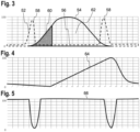
- Figure 3 shows a schematic representation of an energy consumption curve 52 of the consumers 34 over a day as well as an energy production curve 54 of the energy producers 18 (for example solar power plants 20) in a decentralized energy supply system 10.
- the energy consumption curve 52 is characterized by a base consumption 56 and two consumption peaks 58.
- the consumption peaks 58 can, for example, be start-up peaks of the production machines 48.
- the energy production curve 54 can, as in Figure 3 shown, vary throughout the day. For example, solar power plants 20 produce particularly large amounts of energy during intense sunlight at midday.
- a first portion 60 (peak load storage charging period") of this energy can, for example, be used to directly charge the peak load storage 36, 38 when required.
- a second portion 62 (base load storage charging period), on the other hand, can be used to charge the base load storage 40, 50.
- Figure 4 shows a schematic representation of a state of charge 64 ("base load storage state of charge”) of the first base load storage 40. Initially, the state of charge 64 decreases because the energy generators 18 hardly produce any energy at the beginning of the day and energy is taken from the base load storage 40 to cover the basic consumption 56.
- the state of charge 64 of the first base load storage unit 40 increases again as it is charged by the electrical energy generated by the energy generators 18.
- the charge state 64 of the base load storage 40 subsequently drops again because a peak load storage charge is necessary after one of the consumption peaks 58 and the energy for this cannot be provided directly by the energy generators 18.
- FIG. 5 shows a schematic representation of a charge state 66 ("charge state of peak load storage") of the first peak load storage 36.
- the consumption peaks 58 are, as already described, covered by energy from the peak load storage 36. Therefore, the charge state 66 of the first peak load storage 36 drops during the consumption peaks 58.
- the energy to refill the first peak load storage 36 can be provided by the energy generators 18 directly and/or by one of the base load storages 40, 50.
Landscapes
- Engineering & Computer Science (AREA)
- Power Engineering (AREA)
- Supply And Distribution Of Alternating Current (AREA)
Priority Applications (1)
| Application Number | Priority Date | Filing Date | Title |
|---|---|---|---|
| EP23158565.4A EP4422011A1 (fr) | 2023-02-24 | 2023-02-24 | Système de stockage d'énergie distribué et système d'alimentation en énergie distribué |
Applications Claiming Priority (1)
| Application Number | Priority Date | Filing Date | Title |
|---|---|---|---|
| EP23158565.4A EP4422011A1 (fr) | 2023-02-24 | 2023-02-24 | Système de stockage d'énergie distribué et système d'alimentation en énergie distribué |
Publications (1)
| Publication Number | Publication Date |
|---|---|
| EP4422011A1 true EP4422011A1 (fr) | 2024-08-28 |
Family
ID=85382839
Family Applications (1)
| Application Number | Title | Priority Date | Filing Date |
|---|---|---|---|
| EP23158565.4A Pending EP4422011A1 (fr) | 2023-02-24 | 2023-02-24 | Système de stockage d'énergie distribué et système d'alimentation en énergie distribué |
Country Status (1)
| Country | Link |
|---|---|
| EP (1) | EP4422011A1 (fr) |
Citations (4)
| Publication number | Priority date | Publication date | Assignee | Title |
|---|---|---|---|---|
| US20180183239A1 (en) * | 2015-08-26 | 2018-06-28 | Tokyo Electric Power Company Holdings, Inc. | Method for controlling storage battery system |
| EP3567691A1 (fr) * | 2018-05-08 | 2019-11-13 | Hitachi, Ltd. | Système de stockage d'énergie composite et procédé de stockage d'énergie |
| US20210036514A1 (en) * | 2018-02-06 | 2021-02-04 | Tdk Corporation | Direct current power supplying system |
| US20220037900A1 (en) * | 2019-04-24 | 2022-02-03 | Toshiba Mitsubishi-Electric Industrial Systems Corporation | Power system |
-
2023
- 2023-02-24 EP EP23158565.4A patent/EP4422011A1/fr active Pending
Patent Citations (4)
| Publication number | Priority date | Publication date | Assignee | Title |
|---|---|---|---|---|
| US20180183239A1 (en) * | 2015-08-26 | 2018-06-28 | Tokyo Electric Power Company Holdings, Inc. | Method for controlling storage battery system |
| US20210036514A1 (en) * | 2018-02-06 | 2021-02-04 | Tdk Corporation | Direct current power supplying system |
| EP3567691A1 (fr) * | 2018-05-08 | 2019-11-13 | Hitachi, Ltd. | Système de stockage d'énergie composite et procédé de stockage d'énergie |
| US20220037900A1 (en) * | 2019-04-24 | 2022-02-03 | Toshiba Mitsubishi-Electric Industrial Systems Corporation | Power system |
Non-Patent Citations (1)
| Title |
|---|
| ZUOMIN WANG ET AL: "Study on optimization of hybrid energy storage configuration", 2017 IEEE CONFERENCE ON ENERGY INTERNET AND ENERGY SYSTEM INTEGRATION (EI2), IEEE, 26 November 2017 (2017-11-26), pages 1 - 6, XP033288417, DOI: 10.1109/EI2.2017.8245680 * |
Similar Documents
| Publication | Publication Date | Title |
|---|---|---|
| EP3221945B1 (fr) | Centrale électrique virtuelle à équilibrage prioritaire des installations d'accumulation d'énergie électrique | |
| EP2293409B1 (fr) | Unité d'îlot d'un réseau d'énergie en îlot pour la communication de demandes d'énergie avec une autre unité d'îlot | |
| DE102014203074A1 (de) | Photovoltaik-Leistungserzeugungssystem, Steuerungsverfahren und Steuerungsprogramm für ein Photovoltaik-Leistungserzeugungssystem | |
| EP3195442B1 (fr) | Procédé et dispositif pour faire fonctionner une centrale électrique à rendement électrique fluctuant qui est relié à un réseau à courant alternatif limité en plus d'un générateur de réseau et d'au moins une charge | |
| DE102013102603A1 (de) | Verfahren für einen Schwarzstart eines Kraftwerks mit mehreren einem Wechselstromnetz zuschaltbaren Wechselrichtern | |
| DE102008046747A1 (de) | Verfahren zum Betrieb eines Produktionssystems und/oder einer lokalen Anlage im Inselbetrieb | |
| EP3602722A1 (fr) | Procédé de démarrage d'un réseau de production d'énergie | |
| DE3706238A1 (de) | Vorrichtung zur elektrischen energiespeicherung | |
| DE102008044842A1 (de) | Vorrichtung zur Energieversorgung eines Bahnnetzes | |
| DE102014210010A1 (de) | Verfahren und Vorrichtung zum Betrieb eines elektrischen Energiespeichersystems | |
| EP2875560B1 (fr) | Procédé de réglage du rapport entre l'énergie électrique injectée et prélevée dans un réseau d'alimentation en énergie électrique | |
| EP3336998A1 (fr) | Installation auxiliaire d'alimentation, convertisseur pour une installation auxiliaire d'alimentation ainsi que procédé de fonctionnement d'une installation auxiliaire d'alimentation | |
| DE102006050509A1 (de) | Verfahren zur geregelten Auskopplung elektrischer Energie aus dem Niederspannungsnetz | |
| EP3382841B1 (fr) | Utilisation hybride d'accumulateurs d'énergie | |
| EP3837753A1 (fr) | Procédé pour la commande de consommateurs électriques d'un réseau d'alimentation électrique | |
| WO2024099504A1 (fr) | Système et procédé de décharge d'un réseau électrique local et d'un réseau électrique maître | |
| DE102016104989A1 (de) | Zwischenlager für Batterieeinheiten | |
| EP3751691B1 (fr) | Système d'alimentation électrique | |
| DE102010023112A1 (de) | Energieübertragungseinrichtung | |
| EP2685590B1 (fr) | Accumulateur-tampon d'une installation de production d'énergie à courant continu | |
| EP2820735A1 (fr) | Appareil électrique et procédé pour le pilotage d'un générateur d'énergie électrique | |
| EP3900142A1 (fr) | Procédé de commande d'une installation électrique ayant une pluralité d'appareils électriques, unité de commande et installation électrique équipée d'une unité de commande de ce genre | |
| EP3422522A1 (fr) | Fourniture de puissance électrique à un réseau d'alimentation électrique à l'aide d'un dispositif de fourniture à dynamique accrue | |
| WO2016045738A1 (fr) | Centrale électrique | |
| EP4487441B1 (fr) | Procédé d'alimentation en énergie dans un réseau local d'alimentation en énergie |
Legal Events
| Date | Code | Title | Description |
|---|---|---|---|
| PUAI | Public reference made under article 153(3) epc to a published international application that has entered the european phase |
Free format text: ORIGINAL CODE: 0009012 |
|
| STAA | Information on the status of an ep patent application or granted ep patent |
Free format text: STATUS: REQUEST FOR EXAMINATION WAS MADE |
|
| 17P | Request for examination filed |
Effective date: 20231215 |
|
| AK | Designated contracting states |
Kind code of ref document: A1 Designated state(s): AL AT BE BG CH CY CZ DE DK EE ES FI FR GB GR HR HU IE IS IT LI LT LU LV MC ME MK MT NL NO PL PT RO RS SE SI SK SM TR |
|
| RAP3 | Party data changed (applicant data changed or rights of an application transferred) |
Owner name: MURRELEKTRONIK GMBH |