EP4424257A2 - Générateur d'électrochirurgie pourvu d'inverseur à dynamique améliorée - Google Patents
Générateur d'électrochirurgie pourvu d'inverseur à dynamique améliorée Download PDFInfo
- Publication number
- EP4424257A2 EP4424257A2 EP24189146.4A EP24189146A EP4424257A2 EP 4424257 A2 EP4424257 A2 EP 4424257A2 EP 24189146 A EP24189146 A EP 24189146A EP 4424257 A2 EP4424257 A2 EP 4424257A2
- Authority
- EP
- European Patent Office
- Prior art keywords
- voltage
- inverter cells
- inverter
- hvc
- group
- Prior art date
- Legal status (The legal status is an assumption and is not a legal conclusion. Google has not performed a legal analysis and makes no representation as to the accuracy of the status listed.)
- Pending
Links
Images


Classifications
-
- A—HUMAN NECESSITIES
- A61—MEDICAL OR VETERINARY SCIENCE; HYGIENE
- A61B—DIAGNOSIS; SURGERY; IDENTIFICATION
- A61B18/00—Surgical instruments, devices or methods for transferring non-mechanical forms of energy to or from the body
- A61B18/04—Surgical instruments, devices or methods for transferring non-mechanical forms of energy to or from the body by heating
- A61B18/12—Surgical instruments, devices or methods for transferring non-mechanical forms of energy to or from the body by heating by passing a current through the tissue to be heated, e.g. high-frequency current
- A61B18/1206—Generators therefor
-
- H—ELECTRICITY
- H02—GENERATION; CONVERSION OR DISTRIBUTION OF ELECTRIC POWER
- H02M—APPARATUS FOR CONVERSION BETWEEN AC AND AC, BETWEEN AC AND DC, OR BETWEEN DC AND DC, AND FOR USE WITH MAINS OR SIMILAR POWER SUPPLY SYSTEMS; CONVERSION OF DC OR AC INPUT POWER INTO SURGE OUTPUT POWER; CONTROL OR REGULATION THEREOF
- H02M7/00—Conversion of AC power input into DC power output; Conversion of DC power input into AC power output
- H02M7/42—Conversion of DC power input into AC power output without possibility of reversal
- H02M7/44—Conversion of DC power input into AC power output without possibility of reversal by static converters
- H02M7/48—Conversion of DC power input into AC power output without possibility of reversal by static converters using discharge tubes with control electrode or semiconductor devices with control electrode
- H02M7/483—Converters with outputs that each can have more than two voltages levels
-
- H—ELECTRICITY
- H02—GENERATION; CONVERSION OR DISTRIBUTION OF ELECTRIC POWER
- H02M—APPARATUS FOR CONVERSION BETWEEN AC AND AC, BETWEEN AC AND DC, OR BETWEEN DC AND DC, AND FOR USE WITH MAINS OR SIMILAR POWER SUPPLY SYSTEMS; CONVERSION OF DC OR AC INPUT POWER INTO SURGE OUTPUT POWER; CONTROL OR REGULATION THEREOF
- H02M7/00—Conversion of AC power input into DC power output; Conversion of DC power input into AC power output
- H02M7/42—Conversion of DC power input into AC power output without possibility of reversal
- H02M7/44—Conversion of DC power input into AC power output without possibility of reversal by static converters
- H02M7/48—Conversion of DC power input into AC power output without possibility of reversal by static converters using discharge tubes with control electrode or semiconductor devices with control electrode
- H02M7/53—Conversion of DC power input into AC power output without possibility of reversal by static converters using discharge tubes with control electrode or semiconductor devices with control electrode using devices of a triode or transistor type requiring continuous application of a control signal
- H02M7/537—Conversion of DC power input into AC power output without possibility of reversal by static converters using discharge tubes with control electrode or semiconductor devices with control electrode using devices of a triode or transistor type requiring continuous application of a control signal using semiconductor devices only, e.g. single switched pulse inverters
- H02M7/5387—Conversion of DC power input into AC power output without possibility of reversal by static converters using discharge tubes with control electrode or semiconductor devices with control electrode using devices of a triode or transistor type requiring continuous application of a control signal using semiconductor devices only, e.g. single switched pulse inverters in a bridge configuration
- H02M7/53871—Conversion of DC power input into AC power output without possibility of reversal by static converters using discharge tubes with control electrode or semiconductor devices with control electrode using devices of a triode or transistor type requiring continuous application of a control signal using semiconductor devices only, e.g. single switched pulse inverters in a bridge configuration with automatic control of output voltage or current
-
- A—HUMAN NECESSITIES
- A61—MEDICAL OR VETERINARY SCIENCE; HYGIENE
- A61B—DIAGNOSIS; SURGERY; IDENTIFICATION
- A61B18/00—Surgical instruments, devices or methods for transferring non-mechanical forms of energy to or from the body
- A61B2018/00571—Surgical instruments, devices or methods for transferring non-mechanical forms of energy to or from the body for achieving a particular surgical effect
- A61B2018/00607—Coagulation and cutting with the same instrument
-
- A—HUMAN NECESSITIES
- A61—MEDICAL OR VETERINARY SCIENCE; HYGIENE
- A61B—DIAGNOSIS; SURGERY; IDENTIFICATION
- A61B18/00—Surgical instruments, devices or methods for transferring non-mechanical forms of energy to or from the body
- A61B2018/00636—Sensing and controlling the application of energy
- A61B2018/00696—Controlled or regulated parameters
- A61B2018/00767—Voltage
-
- A—HUMAN NECESSITIES
- A61—MEDICAL OR VETERINARY SCIENCE; HYGIENE
- A61B—DIAGNOSIS; SURGERY; IDENTIFICATION
- A61B18/00—Surgical instruments, devices or methods for transferring non-mechanical forms of energy to or from the body
- A61B18/04—Surgical instruments, devices or methods for transferring non-mechanical forms of energy to or from the body by heating
- A61B18/12—Surgical instruments, devices or methods for transferring non-mechanical forms of energy to or from the body by heating by passing a current through the tissue to be heated, e.g. high-frequency current
- A61B18/1206—Generators therefor
- A61B2018/1273—Generators therefor including multiple generators in one device
Definitions
- the invention relates to an electrosurgery generator which is designed to deliver a high-frequency alternating voltage to an electrosurgical instrument. It comprises a direct voltage supply and a high-voltage inverter which is fed by the direct voltage supply and generates a high-frequency alternating voltage which is applied to an output for connecting the electrosurgical instrument.
- high-frequency alternating current is used in particular for cutting or severing tissue and for removing body tissue in the sense of thermal resection (so-called electric scalpel).
- the operating principle is based on heating the tissue to be cut.
- One advantage is that the cut can also be used to stop the bleeding by closing the affected vessels (coagulation). This requires considerable power, namely at frequencies of 200 kHz or higher up to 4000 kHz, typically around 400 kHz. At such frequencies, body tissue behaves like an ohmic resistor.
- the specific resistance depends strongly on the type of tissue; for example, the specific resistances of muscle, fat or bone differ greatly from one another, up to a factor of 1000.
- the waveform of the emitted alternating voltage can be continuously sinusoidal or can be modulated with a crest factor of up to 10 at modulation frequencies of up to about 20 kHz.
- the applicant has developed a previously unpublished novel concept for electrosurgical generators using a multilevel inverter. This enables improved controlled generation and output of the alternating voltage for the electrosurgical instrument.
- a complex voltage-variable DC supply is no longer required, but the level (as well as frequency and waveform) of the output alternating voltage is controlled directly via the multilevel inverter.
- the dynamic range is limited, especially with smaller output alternating voltage amplitudes.
- the achievable modulation index decreases as the output voltage decreases. This not only limits the ability to output modulated signal forms (so-called modes), but may also worsen the waveform of the generated alternating voltage.
- the invention is based on the object of providing an electrosurgery generator which provides a higher dynamic range without being dependent on a DC voltage supply with a variable voltage level.
- an electrosurgical generator designed to deliver a high-frequency alternating voltage to an electrosurgical instrument, comprising a direct current supply and a high-voltage inverter which is fed by the direct current supply and generates a high-frequency alternating voltage with variable voltage and frequency which is an output for connecting the electrosurgical instrument
- the invention provides that the inverter is designed as a multilevel inverter controlled by a reference signal for the voltage to be delivered, with at least two groups of inverter cells connected in series, each group being supplied with a different direct voltage and the voltages delivered by the groups being summed up for delivery at the output.
- the invention By dividing the system into at least two groups, the invention combines two seemingly contradictory advantages, namely, on the one hand, enabling fine adjustment of even small voltages or voltage differences at high speed by switching the inverter cells of the group supplied with lower voltage (LVC), and, on the other hand, enabling rapid and large voltage jumps by switching the inverter cells of the group supplied with higher voltage (HVC).
- the invention thus creates a two-channel structure, so to speak, with a heavy-duty channel in which the inverter cells of the group supplied with higher voltage (HVC) are arranged, and with a dynamic channel in which the inverter cells of the group supplied with lower voltage (LVC) are arranged.
- the inverter cells are divided into at least two groups, of which a first group (LVC) is supplied with a lower direct voltage than another, second group (HVC).
- the first group comprises inverter cells for low voltage
- the second group comprises inverter cells for higher voltage.
- LVC low voltage
- the inverter cells for low voltage (LVC) offer the advantage that, due to their lower supply voltage, the switching losses of the inverter cells for low voltage (LVC) are disproportionately lower, and they therefore tolerate frequent switching much better than the inverter cells for higher voltage (HVC), and also result in lower switching losses.
- the low voltage inverter cells (LVC) are designed for a voltage of only one quarter of the higher voltage inverter cells (e.g. 12 V for LVC instead of 48 V for HVC), the switching losses of the low voltage inverter cells (LVC) are only one sixteenth of the switching losses of the higher voltage inverter cells (HVC).
- the low voltage inverter cells (LVC) are particularly suitable not only for fine-tuning the voltage to be output, but this can also be done extremely quickly. - It goes without saying that further groups can also be provided, the inverter cells of which are preferably supplied with further, yet different, direct voltages.
- the groups comprise a first group whose inverter cells are supplied with a lower direct current voltage (LVC) than the inverter cells (HVC) of another, second group.
- LVC direct current voltage
- HVC inverter cells
- high frequency is typically understood to mean frequencies in the range of 200 kHz to 4000 kHz.
- the ultrasound range can also be optionally covered.
- the ultrasound range is understood to mean a frequency range between 20 kHz and 200 kHz.
- High voltage typically means voltages up to 10 kV, preferably up to 5000 V.
- the power provided by electrosurgical generators typically ranges between 1 and 500 watts, although the load impedance can vary widely and the output voltage and power output can change just as rapidly.
- a "different" DC voltage is understood to mean a DC voltage with a different voltage magnitude; a simple reversal of polarity is not a different DC voltage in this sense.
- switching on and switching off for the inverter cells are used synonymously to increase the voltage output by the inverter cells by one level or decrease it by one level.
- the inverter cells are expediently bipolar and designed to output at least three different output voltages, namely positive, negative and zero. In this way, an increase in the number of voltage levels and also a symmetrical, bipolar generation of the alternating voltage can be achieved with simple means. Furthermore, by "reversing" the inverter cells, i.e. by switching the output voltage from positive to negative or vice versa, the output voltage of the respective inverter cells can change by two levels in one go when it switches from positive to negative (or vice versa).
- the direct voltage for the inverter cells with a higher voltage Voltage is in a fixed ratio to the direct voltage and thus the voltage output for the low-voltage inverter cells (LVC). It is particularly preferred if the ratio between the direct voltage sources for the inverter cells of the two groups is an integer voltage multiple. In this way, several inverter cells with a lower voltage (LVC) connected in series, namely a number corresponding to the voltage multiple, produce exactly the voltage level of one inverter cell for a higher voltage (HVC).
- a modulator is expediently provided to control the inverter cells of both groups, which is designed to reduce the switching frequency of the high-voltage inverter cells (HVC) by optionally replacing an actuation of the high-voltage inverter cells (HVC) with an actuation of a plurality of the low-voltage inverter cells (LVC).
- HVC high-voltage inverter cells
- LVC low-voltage inverter cells
- the modulator preferably works together with a tap changer to which the reference signal is applied and which is designed to convert the reference signal into a voltage step signal that is applied to the modulator.
- a reproducible and determined discretization of the reference signal is achieved, which is used to control the inverter cells of the multilevel inverter and specifies at least one voltage level (and usually also the curve shape) of the alternating voltage generated.
- HVC higher voltage
- LVC lower voltage
- the number of inverter cells of higher voltage (HVC) to be switched corresponds to the integer part of a division of the voltage level by the nominal voltage of the individual inverter cell of higher voltage (HVC), and the remainder determines the number of inverter cells of lower voltage (LVC) for fine adjustment.
- the modulator is further designed to vary the number of higher voltage inverter cells (HVC) to be switched based on at least one predeterminable parameter and to determine a further number of low voltage inverter cells (LVC) to be switched and to switch these in opposite directions for compensation.
- HVC higher voltage inverter cells
- LVC low voltage inverter cells
- the number of inverter cells for high voltage on the one hand and inverter cells for low voltage on the other hand to be switched on is not strictly predetermined, but can be optionally varied.
- the modulator thus creates a deliberate ambiguity with regard to the number of inverter cells of higher voltage to be switched (for a given voltage), which then subsequently also varies the number of inverter cells of low voltage to be switched.
- the invention provides the modulator, which varies the numbers for the inverter cells of higher and lower voltage resulting from a strict, determined conversion of the target voltage signal.
- This variation can also be seen as a distortion of the respective number.
- the modulator distorts the numbers of higher voltage inverter cells (HVC) and lower voltage inverter cells (LVC) resulting from a strict deterministic distribution. It could therefore also be described as a planned distorter of the deterministic distribution.
- the same voltage increase can be achieved by switching on four of the low voltage inverter cells (LVC) instead of switching on one of the higher voltage inverter cells (HVC). If the voltage increase is even 60 V, switching on the higher voltage inverter cell (HVC) can be avoided if at least one redundant (fifth) low voltage inverter cell (LVC) is available that can be switched on for this purpose. The reverse applies accordingly for negative voltages.
- a voltage reduction of 36 V can be achieved by avoiding switching (i.e. switching off the already switched on) higher voltage inverter cell (HVC) by switching off two of the switched on low voltage inverter cells (LVC) and operating a third with a negative voltage of 12 V, resulting in an overall voltage reduction of the desired 36 V without the need to switch the higher voltage inverter cell (HVC) (which has higher switching losses).
- the modulator decides whether the change should be made by switching an LVC or by switching an HVC and, in this example, three LVCs.
- the modulator is actuated via an enable signal and that a change detector is provided which is designed to detect a change in the reference signal and to apply the enable signal to the modulator.
- the modulator does not need to make any switches when the reference signal is unchanged, but only when the reference signal changes anyway. The latter is detected by the change detector.
- This interacts with the modulator in such a way that it applies an enable signal to the modulator when a change is detected. In this way, the activity of the modulator is reduced to those cases in which a change in the reference signal occurs.
- the change detector monitors the (voltage) step signal generated by a tap changer. This reduces the activity of the modulator to those Cases when the change in the reference signal is such that it also leads to a change in the (voltage) step signal.
- the inverter cells expediently each have a potential decoupling on the output side.
- the invention makes use of the fact that by definition alternating voltage is present on the output side of the inverter cells, so that a reliable potential separation of the voltages ultimately emitted by the inverter cells can be achieved with simple and inexpensive transformers in a relatively inexpensive manner (compared to isolated individual direct voltage sources, as would be required on the input side).
- the predeterminable parameter comprises a switching frequency of the higher voltage inverter cells (HVC), and the modulator is designed to minimize this switching frequency.
- HVC higher voltage inverter cells
- the modulator is designed to minimize this switching frequency. It can also be taken into account that due to the higher voltage of the inverter cells (HVC), the power loss caused by switching is disproportionately greater. There is even a quadratic relationship, so that switching one of the higher voltage inverter cells (HVC) causes 16 times the switching power loss compared to switching one of the low voltage inverter cells (LVC) at a voltage ratio of 4 to 1, as is the case with 48 V to 12 V, for example. By reducing the frequency of switching the higher voltage inverter cells (HVC), the overall power loss can be reduced considerably.
- the predeterminable parameter comprises a measure of a power loss of the inverter cells
- the modulator is designed to minimize this switching frequency caused by operating the higher voltage inverter cells (HVC).
- the aim is to match the power loss caused by the operation of the low voltage inverter cells (LVC). This is not only beneficial for efficiency, but also brings significant advantages in terms of thermal relief of the switching elements in the inverter cells.
- At least two alternative switching rules for voltage changes are implemented in the modulator, both of which lead to the same voltage change but switch a different number of HVCs.
- the modulator can select from these switching rules when voltage changes occur. By specifying these switching rules, the switching rules can be used to program the modulator to behave accordingly.
- an example of two such alternative switching rules "a)" and “b)” is that according to switching rule a) the output value of the low-voltage inverter cells (LVC) is increased by a step of 12 V and no change occurs in the higher-voltage inverter cells (HVC); or alternatively, according to switching rule b) the voltage delivered by the low voltage inverter cells (LVC) is reduced by three steps with a total of 36 V and at the same time the output voltage of the higher voltage inverter cells (HVC) is increased by one step, i.e. by 48 V - in the end this means the desired increase of 12 V.
- switching rule b) is the more complex one, since it results in significantly higher switching losses due to the switching of one of the higher voltage inverter cells (HVC) than with switching rule a).
- the switching rules are preferably implemented in such a way that when the voltage is increased according to one of the alternative switching rules, the number of higher voltage inverter cells (HVC) remains the same and one of the low voltage inverter cells (LVC) is switched on.
- switching rule a switching rule a
- switching rule b switching rule b
- the number of switched higher voltage inverter cells (HVC) is increased by one and a plurality of low voltage inverter cells (LVC) are switched in opposite directions, whereby this plurality corresponds to the voltage multiple reduced by one. If the voltage is increased by one level, this applies to a corresponding gradation in the output voltages of the low voltage inverter cells (LVC). For larger voltage changes with several such levels, the scheme implemented in the switching rules applies accordingly.
- the number of higher voltage inverter cells (HVC) remains the same and one of the low voltage inverter cells (LVC) is switched off, or according to the other of the alternative switching rules the number of switched higher voltage inverter cells (HVC) is reduced by one and a plurality of low voltage inverter cells (LVC) are switched in opposite directions, with this plurality corresponding to the voltage multiple reduced by one.
- this applies accordingly to larger voltage changes with several stages.
- switching ranges are preferably different for positive and negative polarity of the output voltage. This allows the polarity of the voltage delivered by the inverter to be taken into account.
- Switching ranges define value ranges for the switching rules. It is practical to provide that, with a positive output voltage, an increase in the inverter cells with higher voltage (HVC) should be delayed as long as possible. With a negative However, if the output voltage value is slowly increasing towards zero, it is advisable to switch an increase in the higher voltage inverter cells (HVC) as soon as possible, taking hysteresis into account if necessary.
- a hysteresis is optionally provided to avoid unnecessarily frequent switching on and off of higher voltage inverter cells (HVC) in the event of small voltage changes. It is particularly useful to block switching of the higher voltage inverter cells (HVC) in the event of multiple changes between voltage increase and decrease, with additional low voltage inverter cells (LVC) preferably being switched when the voltage increase or decrease exceeds the voltage value of the higher voltage inverter cells (HVC).
- HVC higher voltage inverter cells
- the limits of the switching ranges can be changed dynamically during operation, preferably depending on the state variables of the inverter cells of higher voltage (HVC) and low voltage (LVC), in particular their respective switch-on time, magnetic flux and/or temperature.
- HVC higher voltage
- LVC low voltage
- the operating state of the inverter cells and their components can be taken into account.
- the magnetic flux in the inverter cells can be monitored. in order to avoid saturation of the inverter cells in particular.
- This can be done by selecting a switching state for the output of positive voltage so that it is as long as the switching state for the output of negative voltage. In this way, a balance can be achieved.
- HVC higher voltage inverter cells
- a monitoring unit can be provided which is designed to determine magnetic flux in the higher voltage inverter cells (HVC) and/or low voltage inverter cells (LVC) and to store a value for the magnetic flux determined in this way.
- the magnetic flux in the respective inverter cells can thus be monitored and saturation of the inverter cells can be avoided by preferably switching them with opposite voltage polarity until the magnetic flux is balanced again.
- a balancing unit can be provided which interacts with the monitoring unit and is designed such that when the voltage of the higher voltage inverter cells (HVC) or low voltage inverter cells (LVC) increases, it switches those with low magnetic flux first, and when the voltage decreases, it switches those with high magnetic flux first. Balancing can thus be carried out in an efficient manner, whereby overloading of individual inverter cells and the associated risk of failure can be effectively prevented.
- a switch-on time monitor for the higher voltage inverter cells (HVC) or low voltage inverter cells (LVC) can advantageously be provided, which The duration of a positive or negative voltage output of the HVC and LVC is determined and the respective inverter cells (HVC or LVC) are switched off when a preset limit is exceeded. In this way, the dwell time of the individual inverter cells can be effectively controlled and limited. If one of the inverter cells, and the higher voltage inverter cells (HVC) are particularly relevant here, is switched on for too long, it is not used but switched to idle and another, less loaded higher voltage inverter cell (HVC) is activated instead.
- a control signal generator is provided for the multilevel inverter, which is designed to generate a reference signal for controlling the multilevel inverter, wherein the reference signal is a pattern for the alternating voltage to be delivered by the electrosurgical generator, in particular with regard to amplitude, frequency, waveform and/or duty cycle, wherein the waveform is preferably freely selectable.
- the reference signal is a pattern for the alternating voltage to be delivered by the electrosurgical generator, in particular with regard to amplitude, frequency, waveform and/or duty cycle, wherein the waveform is preferably freely selectable.
- a peak detector is expediently provided, to which the reference signal is applied and which acts with its output on the modulator, in particular reducing or preventing switching of high-voltage inverter cells (HVC).
- HVC high-voltage inverter cells
- the peak detector can be used for the final steps to increase the voltage by blocking the connection of another inverter cell for higher voltage (HVC), taking into account the voltage drop that will soon occur. Instead, another of the low-voltage inverter cells (LVC) (which can be switched with low loss) can be activated.
- HVC higher voltage
- LVC low-voltage inverter cells
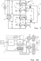
- FIG. 1 An electrosurgical generator according to an embodiment of the invention is shown in Figure 1
- the electrosurgical generator designated in its entirety with the reference number 1, comprises a housing 11 which is provided with an output connection 14 for an electrosurgical instrument 16, in the embodiment shown this is an electric scalpel. It is connected to the output connection 14 of the electrosurgical generator 1 via a connector plug 15 of a high-voltage connecting cable.
- the power output to the electrosurgical instrument 16 can be changed via a power controller 12.
- a direct current supply 2 is provided to supply power to the electrosurgical generator 1, which can be connected to the public power grid via a power cable (not shown) and is fed from it.
- the direct current supply 2 is a power supply unit. It comprises a rectifier and feeds a direct current intermediate circuit 20 with direct current, the level of which is preferably fixed and is, for example, 48 volts.
- the direct current level is variable between 0 and about 400 volts, whereby the absolute level of the direct current can depend in particular on the set power, the type of electrosurgical instrument 16 and/or its load impedance, which in turn depends on the type of tissue being treated.
- an internal power supply unit is not necessary, so the direct current supply can also be implemented by an external power supply unit, or a direct DC supply is provided, for example 24 volts in vehicles or 48 volts in stationary applications.
- An inverter is fed from the DC voltage intermediate circuit 20, which generates high-frequency alternating voltage in the high voltage range from the supplied DC voltage, with predeterminable frequencies in the range between 200 kHz and 4 MHz.
- the inverter is designed as a multilevel inverter 4, as will be explained in more detail below.
- the frequency and waveform of the high-frequency alternating voltage to be generated by the multilevel inverter 4 are specified by an inverter control 41 on the basis of a reference signal 43 generated by a control signal generator 40 (see. Fig.4 ).
- the high-frequency alternating voltage generated by the multilevel inverter 4 is fed via an output line 13, an output transformer 7 to increase the output voltage to the range of a few kilovolts and a low-pass filter 8 and, protected by a block capacitor 17 against undesirable direct current components, output at the output connection 14 for connection to the electrosurgical instrument 16. Furthermore, the voltage and current of the high voltage generated and output by the multilevel inverter 4 are measured by means of a combined voltage and current sensor 18 and the measurement signals are fed to a processing unit 19 which applies the corresponding data on the output voltage, current and power as feedback to an operating control 10 of the electrosurgical generator 1, which in turn communicates with the control signal generator 40. The power controller 12 is also connected to the operating control 10.
- the operating control 10 is also designed to set various so-called modes, which are typically stored voltage/time curves.
- a selection switch 12' is provided for the user to select the mode.
- the operating control 10 further cooperates with the control signal generator 40, which is designed to generate the reference signal 43 for the alternating voltage to be output, in particular with respect to amplitude, frequency, curve shape and duty cycle, and to output it to an inverter control 41.
- the multilevel inverter 4 comprises a plurality of inverter cells 5 connected in series, which are controlled by the inverter control 41.
- the inverter cells 5 are divided into two groups I and II, which are fed in groups with DC voltage of different levels.
- a first is referred to as “Group I” and comprises low voltage inverter cells (LVC), namely in the example in Figure 2 three inverter cells 5-1, 5-2 to 5-3. They are fed by a DC voltage source with low DC voltage, in the example 12 V.
- LVC low voltage inverter cells
- HVC high voltage
- the example shown comprises two inverter cells 5-4, 5-5, which are fed with a higher direct voltage, in the example 48 V.
- a selector 3 which determines the inverter cells 5 to be controlled, in particular the number "m” of high-voltage inverter cells (HVC) of group II to be controlled and the number "n” of low-voltage inverter cells (LVC) of group I to be switched on.
- a direct current source with a specific direct current voltage is connected to the input (shown on the left in the drawing) of each of the inverter cells 5.
- the respective inverter cell 5 generates an alternating current from this, which is output as alternating current at the output (shown on the right in the drawing) of the respective inverter cell 5.
- the number of inverter cells is not limited and can be arbitrary.
- the inverter cells 5 are in the Figure 2a numbered with the designation "5-1", “5-2" to "5-5", whereby the number 5 is an example and any number of at least two inverter cells can be provided.
- the direct voltages applied to the input of the respective inverter cell 5 are optionally coupled in terms of potential via a guide rail 50. Accordingly, the alternating voltage output at the output of the respective inverter cell 5 is designated as "V_1", “V_2" up to "V_5".
- V_1 the alternating voltage output at the output of the respective inverter cell 5
- V_2 the alternating voltage output at the output of the respective inverter cell 5
- the invention increases the effort in terms of DC voltage sources because several (in the example: two) are now required instead of just one.
- the number of voltage levels increases considerably, starting from eleven voltage levels with only one DC voltage source to more than double with 23 voltage levels.
- the two DC voltage sources do not need to be isolated from each other in terms of potential, but they can share a common reference potential, as in Figure 2a is realized by means of the guide rail 50.
- This also makes it possible to generate the lower DC voltage from the higher DC voltage, which can be the DC voltage in the intermediate circuit 20, by means of a DC voltage converter 42, in particular a DC/DC step-down converter.
- it would be designed for a ratiometric supply with a reduction ratio of 4:1, as in Figure 2b
- An advantage of this configuration using ratiometric supply is that changes or fluctuations in the higher DC voltage are then reflected in a proportional form in the lower DC voltage so that the relative gradation is maintained.
- the output voltage can be increased by 12V in two different ways: conventionally by connecting another 12V inverter cell or by connecting a 48V inverter cell combined with switching off three 12V inverter cells.
- the structure of the individual inverter cells 5 and their interaction are shown as an example in the schematic circuit diagram according to Figure 3.
- a total of two inverter cells 5-1 and 5-5 are shown there in a cascaded arrangement in order to also show their supply with direct voltage of different levels.
- the common direct voltage source 2 is shown on the left edge of the image with a supply voltage Vin of 48 volts.
- a stabilization capacitor 23 is assigned to it. This supplies the two inverter cells 5-3 and 5-4 with direct voltage.
- Four power switches are provided, which act as current valves and are arranged in an H-bridge circuit.
- the power switches are semiconductor power switches, for example designed as IGBT, MOS-FET, GaN-FET.
- the power switches 51, 53 are connected in series and form a first branch, and the power semiconductors 52, 54 are also connected in series and form a second branch.
- the midpoints of the two branches are led out and connected to the two ends of a primary winding 61 of a first transformer 6-5.
- the transformer 6-5 also has a secondary winding 62, the transformation ratio being 1:1 (it should be noted that a different transformation ratio can also be provided, in particular in order to achieve pre-amplification, for example with a transformation ratio of 1:2).
- Connected to the secondary winding 62 is a Output line 13, which leads to the output connection 14 of the electrosurgical generator 1 (if necessary via a Fig.3 not shown low-pass filter 8 and an output transformer 7, see Fig.1 ).
- the two power switches 51, 53 of the first branch are controlled with a common signal C1.a, with this signal being fed inverted to the power switch 53.
- the two power switches 52, 54 of the second branch are also controlled with a common signal C1.b, with this signal being fed inverted to the power switch 52.
- the signals C1.a and C1.b are generated in a manner known per se by the inverter control 41. This means that when there is a HIGH signal from C1.a, the power switch 51 switches through and the power switch 53 blocks, i.e. the first power branch applies a positive potential to the upper connection of the primary winding 61 of the transformer 6-1.
- the power switch 54 switches through while the power switch 52 blocks.
- the second power branch therefore applies a negative potential to the lower connection of the primary winding 61. If the signal from C1.a or C1.b is LOW, the opposite applies, i.e. the polarity on the primary winding 61 is reversed. An alternating voltage is thus generated by the inverter cell 5-1 and applied to the primary winding 61 of the transformer 6-1.
- the second inverter cell 5-1 has an identical structure, but is fed from the DC voltage source 2 via the ratiometric DC-DC converter 42, which reduces the voltage to a quarter of the input voltage. It therefore outputs a DC voltage of 12 volts, which supplies the second inverter cell 5-1 in the same way as the first inverter cell 5-5.
- the same reference numbers are therefore used for similar elements in the figure.
- It is controlled by means of control signals C2.a and C2.b, which are generated by the inverter control 41, for example by means of known pulse width modulation (PWM), in a manner corresponding to that described above. It therefore also outputs an alternating voltage at its output, which is applied to a primary winding 61 of a second transformer 6-1.
- PWM pulse width modulation
- the two inverter cells 5-1 and 5-5 are connected in terms of potential. This means that the alternating voltages directly output by the inverter cells 5-1 and 5-5 cannot simply be added together, since they are linked to one another in terms of their potential. However, since these output alternating voltages are fed to the transformers 6-1 and 6-5, the alternating voltages output by the transformers 6-1 and 6-5 are each potential-free and can easily be added together to form a common output voltage that is present on the output line 13. However, if the inverter cells 5-1 and 5-5 are potential-decoupled by a corresponding design of the DC-DC converter, the output alternating voltages can also be added directly by series connection without these transformers.
- the total voltage generated and summed in this way (and by other inverter cells 5-2 to 5-4) is output via the output line 13, at the end of which the low-pass filter 8 is arranged.
- It can be designed, for example, as a second-order filter comprising an inductance and a capacitance. It should be noted that stray inductances of the transformers 6-1 to 6-n also contribute to the inductance of the low-pass filter and can at least partially replace it.
- the low-pass filter 8 is tuned in such a way that interference in the generated alternating voltage due to the switching frequency of the power switches are filtered out in the inverter cells 5 of the multilevel inverter 4.
- the output of the low-pass filter 8 is applied to a primary winding of the output transformer 7, which causes a galvanic isolation of the output connection 14 connected to the secondary winding.
- a block capacitor 17 is also provided. This serves as a safety element to prevent the delivery of direct current components to the surgical instrument 16.
- the control signal generator 40 generates a reference signal 43 for controlling the multilevel inverter 4, in particular on the basis of specifications from the operating control 10.
- This is an alternating voltage signal that is typically sinusoidal and has a certain frequency and amplitude.
- the reference signal 43 is applied to the selector 3, which uses it to determine the number and type (HVC or LVC) of the inverter cells 5 to be controlled, broken down into low-voltage inverter cells (LVC) from group I and high-voltage inverter cells (HVC) from group II.
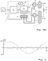
- the selector 3 comprises a tap changer 31 and a modulator 33.
- the tap changer 31 is designed to convert the typically continuous reference signal 43 into a voltage step signal.
- An example of such a continuous reference signal 43 and a step signal formed from it expressed in steps of 12 V is shown in Figure 6a
- the stepped curve shows the voltage step signal and thus forms a discretization of the reference signal 43 shown by the continuous curve.
- the tap changer 31 can already make a preliminary allocation as to which share of this is allocated to the low voltage inverter cells (LVC) of group I or to the higher voltage inverter cells (HVC) of group II. This can be done, for example, in an embodiment as shown in Figure 4a shown, by minimizing the basic number of inverter cells required to achieve the voltage according to reference signal 43.
- Such a division can comprise two signals, a signal "h” for the basic number of higher voltage inverter cells (HVC) of group II to be switched on and a signal "l” for the basic number of low voltage inverter cells (LVC) of group I to be switched on.
- This can in particular be a purely numerical division, e.g. that to generate a voltage of 84 V, exactly one higher voltage inverter cell (HVC) from group II and three low voltage inverter cells (LVC) from group I are to be controlled.
- the modulator 33 is intended to reduce the switching frequencies of the high-voltage inverter cells (HVC) according to group II.
- low-voltage inverter cells (LVC) according to group I are switched. This is described in more detail below.
- the resulting division by the modulator 33 into the numbers “n” for the low-voltage inverter cells (LVC) of group I to be switched and "m” for the higher-voltage inverter cells (HVC) of group II to be switched varies depending on the situation and is ambiguous according to the invention.
- the thus varied number "n” for the low voltage inverter cells (LVC) of group I to be switched as well as the A varied number "m” are output as output signals from the modulator 33 and applied to sub-controllers 45, 46 for the inverter cells LVC of group I or HVC of group II. These control the respective inverter cells LVC in group I or HVC in group II in a manner known per se.
- the sub-controllers 45, 46 record switching data for the individual inverter cells 5 of the low-voltage inverter cells (LVC) of group I or the high-voltage inverter cells (HVC) of group II. These include, among other things, the duty cycle, counter for the number of switching operations and the magnetic flux through the individual inverter cells 5 and their transformers 6. They transmit corresponding status data via data lines 47, 48 to the modulator 33 and/or an upstream adaptation module 36.
- the modulator 33 does not necessarily have to work continuously. It may be sufficient if it is activated and divides the voltage level signal into the number of low voltage (LVC) and high voltage (HVC) inverter cells to be switched when there is a change in the voltage level signal or in the reference signal 43.
- LVC low voltage
- HVC high voltage
- an optional change detector 32 is provided which monitors the reference signal 43 and activates the modulator 33 when there is a change.
- the tap changer 31' is designed in such a way that it only outputs a discretized reference signal (step signal) 44. From this, the modulator 33 directly determines the number "m" of high-voltage inverter cells (LVC) to be switched and the number "n” of low-voltage inverter cells (LVC) to be switched. This is explained using a simplified example: The tap changer 31' generates a discrete step signal 44 from the reference signal 43. The modulator 33 is designed to compare the step signal 44 with the last previous value of the step signal. The comparison can show that there is an increase, a decrease or a constant. This is detected by the change detector 32'.
- LVC high-voltage inverter cells
- LVC low-voltage inverter cells
- HVC higher voltage inverter cells
- LVC low voltage inverter cells
- HVC inverter cells e.g. in the period from 0.25 to 0.65 ⁇ s and 0.87 to 0.98 ps.
- Both alternatives a), b) lead to the same voltage change by one step, namely by +12 V.
- Alternative b) requires switching of one of the high voltage inverter cells (HVC), which, due to the quadratic relationship with four times the supply voltage, means 16 times higher switching losses compared to one of the low voltage inverter cells (LVC).
- HVC high voltage inverter cells
- LVC low voltage inverter cells
- alternative b) means 19 times higher energy loss than alternative a) of switching rules 34.
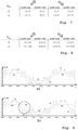
- Input parameters are the polarity of the output voltage and the voltage delivered by the low voltage inverter cells (LVC) of group I, expressed in voltage steps of the LVCs.
- LVC low voltage inverter cells
- switching rule a) applies, ie the voltage delivered by the LVC inverter cells of group I is increased by 12 V.
- switching rule b) is applied, in which the HVC inverters of Group II are switched up by one level, which results in an increase of 48 V, and the LVC inverter cells of group I are compensatorily switched down by three steps, corresponding to -36 V, which ultimately results in the desired increase of 12 V.
- the modulator 33 can also include a hysteresis module 35. It is designed to detect the switching frequency of the high-voltage inverter cells (HVC) of group II and to minimize their switching operations in the event of excessive switching activity. To do this, the hysteresis module 35, for example, acts on the switching rules 34 in such a way that the range limits are changed so that alternative b) becomes less frequent.
- HVC high-voltage inverter cells
- the switching rules 34 and their switching ranges can be adapted by an adaptation module 36, in particular depending on the operating conditions of the multilevel inverter 4 with its inverter cells 5.
- the adaptation module 36 comprises a monitoring unit with a compensation unit 38. It records the magnetic flux in the individual inverter cells of groups I and II and thus influences the switching ranges of the switching rules 34. This allows the switching ranges of the switching rules 34 to be changed dynamically. If the total magnetic flux through the high-voltage inverter cells (HVC) is too high, the switching ranges are changed so that these cells are switched on later and switched off earlier. For this purpose, parameters B and D can be changed as described in the modified switching rules 34 according to Figure 8 are shown. Conversely, if the magnetic flux is too low, the switching ranges can be changed using parameters A and C so that the high voltage inverter cells (HVC) are switched on earlier and switched off later. In this way, the magnetic flux can be balanced and saturation avoided.
- HVC high-voltage inverter cells
- the adaptation module 36 also includes an optional switch-on time monitor 39. This records the duration of a positive or negative voltage output separately for the low voltage inverter cells (LVC) and those for the high voltage inverter cells (HVC). If certain preset limit values are exceeded, the switching ranges can be dynamically adjusted in a similar way to that described above for magnetic saturation. However, it can also be provided that the corresponding highly loaded inverter cells are switched off for a certain time.
- LVC low voltage inverter cells
- HVC high voltage inverter cells
- Figure 9a shows as a starting point the switching behavior according to the switching rules 34 with unchanged switching ranges, as shown in Figure 7
- an optional peak detector 37 is provided.
- the reference signal 43 is applied to it. It is designed to detect the occurrence of signal peaks in the reference signal 43, for example when the amplitude reaches its maximum value. If this is detected, the peak detector 37 can act on the modulator 33 in such a way that a switching of high-voltage inverter cells (HVC), which is actually due according to the switching rules 34, is blocked and instead a surplus low-voltage inverter cell (LVC) is switched to reach the last voltage levels.
- HVC high-voltage inverter cells
- LVC low-voltage inverter cell
- Such an optional surplus LVC inverter cell in group I is in Figure 4 shown with a dashed line. In this way, it is possible to take advantage of the fact that the amplitude maximum is known and easy to determine thanks to the reference signal 43.
- the peak detector 37 detects this and acts on the modulator 33 in such a way as to block or at least minimize the switching operations of high voltage inverter cells 5 (HVC)
Landscapes
- Engineering & Computer Science (AREA)
- Health & Medical Sciences (AREA)
- Life Sciences & Earth Sciences (AREA)
- Surgery (AREA)
- Power Engineering (AREA)
- Medical Informatics (AREA)
- Molecular Biology (AREA)
- Nuclear Medicine, Radiotherapy & Molecular Imaging (AREA)
- Physics & Mathematics (AREA)
- Biomedical Technology (AREA)
- Heart & Thoracic Surgery (AREA)
- Plasma & Fusion (AREA)
- Otolaryngology (AREA)
- Animal Behavior & Ethology (AREA)
- General Health & Medical Sciences (AREA)
- Public Health (AREA)
- Veterinary Medicine (AREA)
- Inverter Devices (AREA)
- Surgical Instruments (AREA)
Applications Claiming Priority (2)
| Application Number | Priority Date | Filing Date | Title |
|---|---|---|---|
| US202163237395P | 2021-08-26 | 2021-08-26 | |
| EP22192317.0A EP4140427B1 (fr) | 2021-08-26 | 2022-08-26 | Générateur d'électrochirurgie pourvu d'inverseur à dynamique améliorée |
Related Parent Applications (1)
| Application Number | Title | Priority Date | Filing Date |
|---|---|---|---|
| EP22192317.0A Division EP4140427B1 (fr) | 2021-08-26 | 2022-08-26 | Générateur d'électrochirurgie pourvu d'inverseur à dynamique améliorée |
Publications (2)
| Publication Number | Publication Date |
|---|---|
| EP4424257A2 true EP4424257A2 (fr) | 2024-09-04 |
| EP4424257A3 EP4424257A3 (fr) | 2024-11-06 |
Family
ID=83081980
Family Applications (2)
| Application Number | Title | Priority Date | Filing Date |
|---|---|---|---|
| EP24189146.4A Pending EP4424257A3 (fr) | 2021-08-26 | 2022-08-26 | Générateur d'électrochirurgie pourvu d'inverseur à dynamique améliorée |
| EP22192317.0A Active EP4140427B1 (fr) | 2021-08-26 | 2022-08-26 | Générateur d'électrochirurgie pourvu d'inverseur à dynamique améliorée |
Family Applications After (1)
| Application Number | Title | Priority Date | Filing Date |
|---|---|---|---|
| EP22192317.0A Active EP4140427B1 (fr) | 2021-08-26 | 2022-08-26 | Générateur d'électrochirurgie pourvu d'inverseur à dynamique améliorée |
Country Status (6)
| Country | Link |
|---|---|
| US (1) | US20230067224A1 (fr) |
| EP (2) | EP4424257A3 (fr) |
| JP (1) | JP7465921B2 (fr) |
| CN (1) | CN115733381A (fr) |
| DE (1) | DE102021122284A1 (fr) |
| ES (1) | ES2995167T3 (fr) |
Families Citing this family (2)
| Publication number | Priority date | Publication date | Assignee | Title |
|---|---|---|---|---|
| DE102022116328B3 (de) * | 2022-06-29 | 2023-09-07 | Olympus Winter & Ibe Gmbh | Elektrochirurgischer Generator mit verbesserter Invertersteuerung und Verfahren zum Betrieb |
| EP4437987A1 (fr) | 2023-03-29 | 2024-10-02 | Olympus Winter & Ibe GmbH | Générateur électrochirurgical |
Citations (1)
| Publication number | Priority date | Publication date | Assignee | Title |
|---|---|---|---|---|
| EP2514380B1 (fr) | 2011-04-21 | 2013-10-02 | Erbe Elektromedizin GmbH | Appareil électrochirurgical avec dispositif de coupe améliorée |
Family Cites Families (9)
| Publication number | Priority date | Publication date | Assignee | Title |
|---|---|---|---|---|
| JP4735188B2 (ja) | 2005-10-25 | 2011-07-27 | 三菱電機株式会社 | 電力変換装置 |
| JP5374336B2 (ja) | 2009-12-01 | 2013-12-25 | 三菱電機株式会社 | 電力変換装置 |
| US9941813B2 (en) * | 2013-03-14 | 2018-04-10 | Solaredge Technologies Ltd. | High frequency multi-level inverter |
| DE102013005277B3 (de) * | 2013-03-26 | 2014-07-03 | Platinum Gmbh | Verfahren zum Umwandeln von Gleichspannung in Wechselspannung und Wechselrichterschaltung dafür |
| US9839470B2 (en) * | 2015-06-30 | 2017-12-12 | Covidien Lp | Electrosurgical generator for minimizing neuromuscular stimulation |
| US10898256B2 (en) | 2015-06-30 | 2021-01-26 | Ethicon Llc | Surgical system with user adaptable techniques based on tissue impedance |
| US10582962B2 (en) * | 2016-01-23 | 2020-03-10 | Covidien Lp | System and method for harmonic control of dual-output generators |
| WO2017152181A1 (fr) * | 2016-03-04 | 2017-09-08 | Qatar Foundation For Education, Science And Community Development | Onduleur multiniveau à cellules en u encapsulées en cascade |
| US10869712B2 (en) | 2016-05-02 | 2020-12-22 | Covidien Lp | System and method for high frequency leakage reduction through selective harmonic elimination in electrosurgical generators |
-
2021
- 2021-08-27 DE DE102021122284.2A patent/DE102021122284A1/de not_active Withdrawn
-
2022
- 2022-08-22 US US17/892,611 patent/US20230067224A1/en active Pending
- 2022-08-25 CN CN202211027722.7A patent/CN115733381A/zh active Pending
- 2022-08-25 JP JP2022134148A patent/JP7465921B2/ja active Active
- 2022-08-26 EP EP24189146.4A patent/EP4424257A3/fr active Pending
- 2022-08-26 EP EP22192317.0A patent/EP4140427B1/fr active Active
- 2022-08-26 ES ES22192317T patent/ES2995167T3/es active Active
Patent Citations (1)
| Publication number | Priority date | Publication date | Assignee | Title |
|---|---|---|---|---|
| EP2514380B1 (fr) | 2011-04-21 | 2013-10-02 | Erbe Elektromedizin GmbH | Appareil électrochirurgical avec dispositif de coupe améliorée |
Also Published As
| Publication number | Publication date |
|---|---|
| JP7465921B2 (ja) | 2024-04-11 |
| US20230067224A1 (en) | 2023-03-02 |
| EP4424257A3 (fr) | 2024-11-06 |
| EP4140427A1 (fr) | 2023-03-01 |
| CN115733381A (zh) | 2023-03-03 |
| JP2023033230A (ja) | 2023-03-09 |
| EP4140427B1 (fr) | 2024-07-24 |
| DE102021122284A1 (de) | 2023-03-02 |
| ES2995167T3 (en) | 2025-02-07 |
Similar Documents
| Publication | Publication Date | Title |
|---|---|---|
| EP4140426B1 (fr) | Générateur d'électrochirurgie pourvu d'inverseur à niveaux multiples pour haute tension hf | |
| DE3531576C2 (de) | Elektrochirurgiegenerator | |
| EP0884830B1 (fr) | Unité d'alimentation de puissance avec un onduleur modulé en largeur d'impulsion, en particulier pour un générateur de rayons X | |
| DE19710319B4 (de) | Schaltung zum Sperren einer Halbleiterschaltvorrichtung bei Überstrom | |
| DE10306347A1 (de) | Leistungszufuhrregeleinheit | |
| DE69206020T2 (de) | Speiseschaltung. | |
| DE60011416T2 (de) | Einen wechselrichter einschliessende leistungsversorgungseinheit | |
| DE2423718A1 (de) | Schaltungsanordnung zur erzeugung einer wechselspannung | |
| EP4140427B1 (fr) | Générateur d'électrochirurgie pourvu d'inverseur à dynamique améliorée | |
| DE2824326C2 (fr) | ||
| DE102009014243A1 (de) | Ortsnetztrafo, bzw. Schaltung für einen elektrischen Verteiltransformator | |
| DE10020357A1 (de) | DC-DC-Konverter | |
| EP0986287A2 (fr) | Circuit de commutation à deux sorties, son circuit électrique et son procédé de commande de la puissance fournie aux sorties du circuit de commutation | |
| DE3743997A1 (de) | Verfahren und vorrichtung zur entkopplung der wirk- und blindleistungsregelung bei einer zwei netze verbindenden hochspannungs-gleichstrom-uebertragungsstrecke | |
| DE4205599B4 (de) | Halbbrücken-Wechselrichter oder eine von einem Vollbrücken-Wechselrichter durch Halbierungsberechnung abgeleitete Schaltungsanordnung in Form eines Halbbrücken-Wechselrichters sowie Verfahren zu deren Steuerung | |
| EP3326281B1 (fr) | Source de tension pour des tensions continues modulées | |
| EP3449554A1 (fr) | Onduleur et procédé pour générer un courant alternatif | |
| EP1623494A1 (fr) | Convertisseur continu-continu comportant un etage de commutation d'entree et plusieurs canaux de sortie | |
| EP3462590A1 (fr) | Hacheur résonant | |
| DE3803583A1 (de) | Schaltverstaerker zur digitalen leistungsverstaerkung | |
| DE102008050242B4 (de) | Hochfrequenz-Chirurgiegerät | |
| DE69521998T2 (de) | Schaltungsanordnung | |
| EP4560912A1 (fr) | Procédé de commande asymétrique pour actionneur de frein modulaire | |
| EP4383549A1 (fr) | Convertisseur continu-continu modulaire | |
| AT409691B (de) | Schaltung zur reduktion der verluste beim umformen, schalten oder steuern elektrischer leistung |
Legal Events
| Date | Code | Title | Description |
|---|---|---|---|
| PUAI | Public reference made under article 153(3) epc to a published international application that has entered the european phase |
Free format text: ORIGINAL CODE: 0009012 |
|
| STAA | Information on the status of an ep patent application or granted ep patent |
Free format text: STATUS: THE APPLICATION HAS BEEN PUBLISHED |
|
| AC | Divisional application: reference to earlier application |
Ref document number: 4140427 Country of ref document: EP Kind code of ref document: P |
|
| AK | Designated contracting states |
Kind code of ref document: A2 Designated state(s): AL AT BE BG CH CY CZ DE DK EE ES FI FR GB GR HR HU IE IS IT LI LT LU LV MC MK MT NL NO PL PT RO RS SE SI SK SM TR |
|
| REG | Reference to a national code |
Ref country code: DE Ref legal event code: R079 Free format text: PREVIOUS MAIN CLASS: A61B0018000000 Ipc: A61B0018120000 |
|
| PUAL | Search report despatched |
Free format text: ORIGINAL CODE: 0009013 |
|
| AK | Designated contracting states |
Kind code of ref document: A3 Designated state(s): AL AT BE BG CH CY CZ DE DK EE ES FI FR GB GR HR HU IE IS IT LI LT LU LV MC MK MT NL NO PL PT RO RS SE SI SK SM TR |
|
| RIC1 | Information provided on ipc code assigned before grant |
Ipc: A61B 18/00 20060101ALN20240927BHEP Ipc: A61B 18/12 20060101AFI20240927BHEP |
|
| STAA | Information on the status of an ep patent application or granted ep patent |
Free format text: STATUS: REQUEST FOR EXAMINATION WAS MADE |
|
| 17P | Request for examination filed |
Effective date: 20250506 |
|
| GRAP | Despatch of communication of intention to grant a patent |
Free format text: ORIGINAL CODE: EPIDOSNIGR1 |
|
| STAA | Information on the status of an ep patent application or granted ep patent |
Free format text: STATUS: GRANT OF PATENT IS INTENDED |
|
| RIC1 | Information provided on ipc code assigned before grant |
Ipc: A61B 18/12 20060101AFI20251023BHEP Ipc: A61B 18/00 20060101ALN20251023BHEP |
|
| INTG | Intention to grant announced |
Effective date: 20251105 |
|
| GRAJ | Information related to disapproval of communication of intention to grant by the applicant or resumption of examination proceedings by the epo deleted |
Free format text: ORIGINAL CODE: EPIDOSDIGR1 |
|
| STAA | Information on the status of an ep patent application or granted ep patent |
Free format text: STATUS: REQUEST FOR EXAMINATION WAS MADE |
|
| GRAP | Despatch of communication of intention to grant a patent |
Free format text: ORIGINAL CODE: EPIDOSNIGR1 |
|
| STAA | Information on the status of an ep patent application or granted ep patent |
Free format text: STATUS: GRANT OF PATENT IS INTENDED |
|
| INTC | Intention to grant announced (deleted) | ||
| RIC1 | Information provided on ipc code assigned before grant |
Ipc: A61B 18/12 20060101AFI20260311BHEP Ipc: A61B 18/00 20060101ALN20260311BHEP |
|
| INTG | Intention to grant announced |
Effective date: 20260323 |