EP4424968A1 - Profilé composite, cadre et procédé de fabrication du profilé composite - Google Patents
Profilé composite, cadre et procédé de fabrication du profilé composite Download PDFInfo
- Publication number
- EP4424968A1 EP4424968A1 EP24159759.0A EP24159759A EP4424968A1 EP 4424968 A1 EP4424968 A1 EP 4424968A1 EP 24159759 A EP24159759 A EP 24159759A EP 4424968 A1 EP4424968 A1 EP 4424968A1
- Authority
- EP
- European Patent Office
- Prior art keywords
- profile
- insulating
- aluminum
- grooves
- composite
- Prior art date
- Legal status (The legal status is an assumption and is not a legal conclusion. Google has not performed a legal analysis and makes no representation as to the accuracy of the status listed.)
- Granted
Links
Images



Classifications
-
- E—FIXED CONSTRUCTIONS
- E06—DOORS, WINDOWS, SHUTTERS, OR ROLLER BLINDS IN GENERAL; LADDERS
- E06B—FIXED OR MOVABLE CLOSURES FOR OPENINGS IN BUILDINGS, VEHICLES, FENCES OR LIKE ENCLOSURES IN GENERAL, e.g. DOORS, WINDOWS, BLINDS, GATES
- E06B3/00—Window sashes, door leaves, or like elements for closing wall or like openings; Layout of fixed or moving closures, e.g. windows in wall or like openings; Features of rigidly-mounted outer frames relating to the mounting of wing frames
- E06B3/04—Wing frames not characterised by the manner of movement
- E06B3/263—Frames with special provision for insulation
- E06B3/26301—Frames with special provision for insulation with prefabricated insulating strips between two metal section members
-
- E—FIXED CONSTRUCTIONS
- E06—DOORS, WINDOWS, SHUTTERS, OR ROLLER BLINDS IN GENERAL; LADDERS
- E06B—FIXED OR MOVABLE CLOSURES FOR OPENINGS IN BUILDINGS, VEHICLES, FENCES OR LIKE ENCLOSURES IN GENERAL, e.g. DOORS, WINDOWS, BLINDS, GATES
- E06B3/00—Window sashes, door leaves, or like elements for closing wall or like openings; Layout of fixed or moving closures, e.g. windows in wall or like openings; Features of rigidly-mounted outer frames relating to the mounting of wing frames
- E06B3/04—Wing frames not characterised by the manner of movement
- E06B3/263—Frames with special provision for insulation
- E06B3/273—Frames with special provision for insulation with prefabricated insulating elements held in position by deformation of portions of the metal frame members
-
- E—FIXED CONSTRUCTIONS
- E06—DOORS, WINDOWS, SHUTTERS, OR ROLLER BLINDS IN GENERAL; LADDERS
- E06B—FIXED OR MOVABLE CLOSURES FOR OPENINGS IN BUILDINGS, VEHICLES, FENCES OR LIKE ENCLOSURES IN GENERAL, e.g. DOORS, WINDOWS, BLINDS, GATES
- E06B3/00—Window sashes, door leaves, or like elements for closing wall or like openings; Layout of fixed or moving closures, e.g. windows in wall or like openings; Features of rigidly-mounted outer frames relating to the mounting of wing frames
- E06B3/04—Wing frames not characterised by the manner of movement
- E06B3/263—Frames with special provision for insulation
- E06B3/26301—Frames with special provision for insulation with prefabricated insulating strips between two metal section members
- E06B3/26305—Connection details
- E06B2003/26314—Provisions for reducing the shift between the strips and the metal section members
-
- E—FIXED CONSTRUCTIONS
- E06—DOORS, WINDOWS, SHUTTERS, OR ROLLER BLINDS IN GENERAL; LADDERS
- E06B—FIXED OR MOVABLE CLOSURES FOR OPENINGS IN BUILDINGS, VEHICLES, FENCES OR LIKE ENCLOSURES IN GENERAL, e.g. DOORS, WINDOWS, BLINDS, GATES
- E06B3/00—Window sashes, door leaves, or like elements for closing wall or like openings; Layout of fixed or moving closures, e.g. windows in wall or like openings; Features of rigidly-mounted outer frames relating to the mounting of wing frames
- E06B3/04—Wing frames not characterised by the manner of movement
- E06B3/263—Frames with special provision for insulation
- E06B2003/26394—Strengthening arrangements in case of fire
-
- E—FIXED CONSTRUCTIONS
- E06—DOORS, WINDOWS, SHUTTERS, OR ROLLER BLINDS IN GENERAL; LADDERS
- E06B—FIXED OR MOVABLE CLOSURES FOR OPENINGS IN BUILDINGS, VEHICLES, FENCES OR LIKE ENCLOSURES IN GENERAL, e.g. DOORS, WINDOWS, BLINDS, GATES
- E06B3/00—Window sashes, door leaves, or like elements for closing wall or like openings; Layout of fixed or moving closures, e.g. windows in wall or like openings; Features of rigidly-mounted outer frames relating to the mounting of wing frames
- E06B3/04—Wing frames not characterised by the manner of movement
- E06B3/263—Frames with special provision for insulation
- E06B3/2634—Frames with special provision for insulation without separate insulating elements, e.g. the heat transmission being reduced by a smaller cross-section
Definitions
- the present invention relates to a composite profile for a window or a door or a facade element, a frame and a method for producing a composite profile for a door or a window or a facade element, in particular with fire protection properties.
- State-of-the-art composite profiles generally have a first profile - usually an external profile - and a second aluminum profile - usually an internal profile - which are connected to one another by at least one element that reduces heat transfer, for example an insulating profile, which can be made of a less conductive material such as plastic.
- an insulating profile which can be made of a less conductive material such as plastic.
- the composite profiles from outside to inside - based on an example installation situation in an external wall - have three or more aluminum profiles and have two or more insulating profile zones.
- one room is to be regarded as an outdoor room and the other room as an indoor room.
- An aluminium profile within the meaning of this document is a profile which is made of aluminium or an aluminium alloy.
- the composite profiles are particularly - but not exclusively - suitable for the manufacture of doors or windows in fire protection design, which then preferably have at least fire resistance class T30 or F30 according to DIN 4102-13 and according to DIN EN 16034 in outdoor use, i.e. for installation in external fire protection walls in fire resistance class EI 2 30-S a C2. They can also be used in doors, windows or facade elements that are not intended as Fire protection walls are designed and/or are used inside buildings.
- Fire protection constructions made of thermally separated profile constructions have also been known for a long time.
- a profile system in fire protection design is described, which consists of an aluminum profile with a central area in which the heat flow is reduced compared to the outer areas by recesses such as punched out areas.
- the disadvantage of such fire protection constructions is that they can bend in the event of a fire, i.e. when the temperatures on the inside and outside are different (bimetal effect).
- the technological background in this context is also the EN 31 09 103 A1 From this document it is known to insert fire protection strips into two hollow chambers of metal profiles.
- the hollow chambers can be connected via bridge webs, which can have openings such as elongated holes.
- fire protection strips that foam up in the event of a fire can be arranged on the bridge webs.
- two aluminum profiles are usually provided, each of which has at least one (or more) undercut groove(s) in its main direction of extension, into which corresponding foot areas of a plastic insulating profile can be inserted.
- an edge web of the grooves of the aluminum profiles known as an anvil, is usually rolled onto the insulating profile.
- EP 1 138 864 A1 temperature-resistant bridge elements preferably made of steel, under which the insulation profiles and the profiles are attached to each other. Then connected (rolled).
- the insulation profiles must be partially milled out, bridge elements must be made as stamped and bent parts made of steel, an adhesive connection must be provided for mounting the bridge elements on the insulation profiles and the bridge elements must be inserted precisely into the milled recesses.
- the components and these work steps are complex and expensive.
- a composite profile is to be created that has very good static properties, which preferably also enable use in fire protection areas.
- the corresponding manufacturing process is to be designed as simply as possible by the invention.
- the present invention solves this problem by the composite profile of claim 1. It also provides the frame of claim 14, the window or door according to claim 15 and the method of claim 16. Advantageous embodiments of the invention are specified in the subclaims.
- a composite profile is first created for a frame of a window or a door, which has the following: a one-piece aluminum profile extending in a main extension direction, to which an insulating profile running parallel to the aluminum profile is fixed in two - different - fastening areas, wherein the one-piece aluminum profile has one or more recesses where it runs next to the insulating profile, between which aluminum webs are formed, which preferably remain there after being cut out or punched out.
- the fastening areas are rolling areas. And it is particularly advantageous and simple and improves the statics that the rolling areas on the aluminum profile comprise grooves, with corresponding foot sections of the insulating profile engaging in these grooves.
- the statics are further positively influenced by the fact that the foot sections are fixed in the grooves perpendicular to the main direction of extension in a tensile-resistant manner. It can be expedient for this purpose that the grooves are fixed in the grooves perpendicular to the main direction of extension in a tensile-resistant manner by at least one means that increases the tensile strength.
- the respective grooves are designed as undercut grooves with respect to the section perpendicular to the main direction of extension, into which the corresponding foot sections engage in the manner of a tongue and groove connection, with the grooves widening continuously or in sections starting from an opening area in the direction of their groove base and with the foot sections widening correspondingly towards their ends, so that the foot sections are fixed in the grooves perpendicular to the main direction of extension in a tensile-resistant manner by these means.
- the grooves contributes to very good statics if the grooves are open in a section perpendicular to the main extension direction exactly or essentially in the opposite direction and if the corresponding foot sections of the insulating profile, pointing exactly or essentially in opposite directions, engage in these grooves, wherein the foot sections are fixed in the grooves in a shear-resistant manner parallel to the main extension direction or in this main extension direction and against this direction.
- the foot sections are fixed in the grooves in a shear-resistant manner parallel to the main direction of extension with a means that increases the shear strength.
- This means can be formed, for example, from a knurled wire or the like running in the grooves parallel to the feet or also by another means such as a projection on one of the groove webs (e.g. on the groove web called the anvil), which is pressed into the insulating profile when it is rolled onto the insulating profile.
- the aluminum webs run at least partially next to the insulating profile, in particular parallel and transverse or diagonal to the insulating profile. In this way, the static properties of the composite profile are particularly good. It can then even be provided that the webs run at least partially parallel to the insulating profile and support it.
- the insulating profiles and the aluminum webs are formed in a corresponding C-shape at least in sections and preferably lie against one another in sections.
- the prefabricated aluminum profile is preferably and simply designed as a one-piece extruded profile made of aluminum or an aluminum alloy, to which the only insulating profile is fixed.
- the recesses can be rectangular or trapezoidal, for example.
- one or more hollow chambers are formed in the aluminum profile.
- the grooves are each supported by one or more wall sections of the aluminum profile, wherein one of these wall sections runs approximately perpendicular to the respective base wall of the respective groove and wherein the other of these wall sections runs obliquely - preferably at an angle between 20° and 70° - approximately in extension of one side wall of the respective groove.
- the invention also provides a frame composed of several composite profiles according to one or more of the claims related thereto, wherein one or more of the composite profiles of the frame have/have a first aluminum zone I perpendicular to the main plane of the frame towards a first side of the frame, then an insulating zone II made up of the aluminum webs and the insulating profile and then again an aluminum zone (III).
- the one or more respective hollow chambers according to one embodiment are each provided in the aluminum zones I and III.
- a window or door which has at least one such frame.
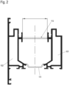
- Fig.1 shows a view of an exemplary aluminum profile 1 and a exemplary insulation profile 2, from which a composite profile 3 ( Fig. 4c, 4d ) for a window or door.
- the composite profile 3 is particularly suitable for the manufacture of a circumferentially closed or non-circumferentially closed frame 4 (see Fig.3 ) for a window or a door, which is composed of three or four or more cut-to-length composite profiles 3a, 3b, 3c, 3d.
- the frame 4 can be a sash frame.
- the frame 4 can also be designed as a window frame.
- the frame 4 extends in a Cartesian coordinate system mainly in an X/Y plane and also has a certain extension in the Z direction perpendicular to its main plane.
- the aluminum profiles 1 then extend preferably perpendicular to the X/Y plane of the frame 4, continuously metallically at least in the area of webs to be described vertically over the entire construction depth Z of the frame 4, i.e. preferably from "outside to inside".
- the aluminum profile 1 can particularly preferably be designed as a one-piece extruded profile made of aluminum or an aluminum alloy.
- the aluminum profile 1 can have one or more hollow chambers 101, 102, which have an advantageous effect on the statics and the thermal insulation, in particular in sections which, after the production of the composite profile to be manufactured, lie outside a section in which the insulating profile 2 of the composite profile runs essentially or exactly parallel to the aluminum profile 1.
- These hollow chambers 101, 102 can be connected to one another via one or more - here two - wall sections 103, 104 running in the Z direction. These wall sections 103, 104 can run exactly or essentially parallel to one another.
- the width of the aluminum profile 1 and the composite profile 3 in the Z direction can be changed by widening the hollow chambers 101, 102 and changing the distance between the wall sections 103, 104.
- grooves 114, 115 can be provided, in particular for fixing fittings for locks or the like.
- the aluminum profile 1 also has at least two spaced-apart, in particular undercut, grooves 105, 106 for inserting two corresponding foot sections 201, 202 of a single insulating profile 2, preferably in sections towards their free ends. This creates the basis for a very tensile connection between the insulating profile 2 and the aluminum profile 1 in the + and - "Z direction".
- the insulating profile 2 preferably extends in a main extension direction (perpendicular to the view of the Fig.1 ) continuously over the entire length of the aluminium profile 1. And also the grooves 105, 106 and the foot sections 201, 202 preferably extend in the main extension direction X perpendicular to the view of the Fig.1 continuously over the entire length of the aluminium profile 1.
- One wall section 103 of the aluminium profile 1 runs between the grooves 105, 106.
- the grooves 105, 106 are open on one side. They are formed on the aluminum profile 1 in such a way that they are open in opposite directions. Here they are directly opposite each other in a line. They are roughly U-shaped, but at least slightly undercut so that the corresponding foot sections 201, 202 of the insulating profile 2, which widen towards their free ends, can be inserted into them in the manner of a tongue and groove system.
- the grooves 105, 106 can be supported on their opposite sides by one or more - here advantageously two - wall sections 107, 108; 109, 110. These each extend to the respective hollow chamber 101, 102.
- One of these wall sections 107, 109 can run approximately centrally perpendicular to the respective base wall of the respective groove 105, 106.
- the other of these wall sections 108 or 110 can run approximately in extension of one side wall of the respective groove 105, 106 obliquely at an angle ⁇ between in particular 20° and 70° to the Z direction, so that the grooves 105, 106 are each very well stabilized by two wall sections.
- the wall sections 107 and 108 on the one hand and 109, 110 on the other hand extend to a respective inner wall 1011 1021 of the two hollow chambers 101 and 102 in the zones I and III and serve as a solid support of the "thermal insulation" zone II made up of the insulating profile 2 and the webs 113 running alongside it.
- the foot sections 201, 202 of the insulating profile 2 preferably also extend in opposite directions.
- a wall-like web region 203 of the insulating profile 2 extends between the foot sections 201, 202 of the insulating profile 2, initially continuous in the main extension direction.
- This web region 203 can - but does not necessarily have to - be C-shaped.
- FIG. 4a A preferred embodiment of the manufacturing process according to the invention is described with reference to Figures 4a to 4d illustrated.
- the cuts of the Fig. 4a and b are located in the main extension direction of the profiles 1,2 at different points.
- the sections of the Fig. 4c and f are located at the positions of Fig. 4a or 4b, but represent a later stage of the manufacturing process.
- Fig. 4a - d From the aluminum profile 1 is in Fig. 4a - d Essentially only one section is shown in which the insulating profile 2 is to be fixed. This section extends - in relation to a frame - in the direction of the construction depth Z, preferably over the depth of an insulating zone II.
- Recesses 111, 112 are now or were previously made in the provided aluminum profile 1, namely at least recesses 111 are made in the wall section 103 next to and between the grooves 105, 106 ( Fig. 2 , 4b ) was introduced.
- each aluminum web 113 remains ( Fig. 2 , Fig. 4c ).
- the insulation profile 2 is positioned with its two feet perpendicular to the plane of the Fig. 2 or Fig. 4a, 4b ) is inserted into the aluminum profile 1.
- at least one groove wall 1051, 1061 - called anvil - of the grooves 105, 106 is rolled onto the foot areas 201, 202 of the insulating profile 2. This is done with high pressing force so that a shear-resistant connection is created between the profiles 1 and 2.
- the insulating profile 2 runs parallel to the aluminum webs 113, ( Fig. 4a, 4d ). It may even rest against them, in particular if the aluminum webs 113 have a projection 116 protruding in the direction of the insulating profile 2.
- This shear strength can be optimized by suitable means to increase the shear strength, such as a knurled wire.
- the foot sections 201, 202 of the insulating profile 2 are fixed in the grooves 201, 202 in a tensile manner perpendicular to the main extension direction by at least one means increasing the tensile strength.
- the respective grooves 105, 106 are designed as undercut grooves with respect to the section perpendicular to the main extension direction, into which the corresponding foot sections 201, 202 of the insulating profile 2 engage in the manner of a tongue and groove connection, wherein the grooves widen continuously or in sections starting from an opening area in the direction of their groove base and wherein the foot sections 201, 202 of the insulating profile 2 widen correspondingly towards their respective free ends, so that the foot sections 201, 202 of the insulating profile 2 are fixed in the grooves 201, 202 by these means perpendicular to the main extension direction (here in the Z direction) in a particularly tensile manner.
- At least one projection 10511, 10611 protruding in the direction of the insulating profile 2 is provided on the respective anvil 1051, 1061, which is embossed into the insulating profile 2 when the anvil 1051 is rolled on, which increases the tensile strength in the Z direction and against this direction in the region of the fastening areas between the profiles 1 and 2.
- the aluminum profile 1 here runs with spaced-apart aluminum webs 113 parallel and transverse or diagonal to the insulating profile 2 in the insulating profile zone.
- the composite profile 3 thus has a frame 4 in the manner of the Fig.4 first a first aluminium zone I, then an insulating zone II, in which the insulating profile 2 and aluminium webs 113 of the aluminium profile 1 next to each other, in particular parallel to each other and then a second aluminium zone III.
- the composite profile 3 produced in this way is very stable. It is also easy to manufacture very precisely, since the depth of the composite profile 3 perpendicular to the frame 4 is not added up from the individual widths of several aluminum profiles and an insulating profile 2, but is determined solely by the width of the aluminum profile 1 provided.
- the recesses 111 can, for example, have a rectangular shape or a trapezoidal shape.
- the recesses 111 can, for example, have an area of more than 30 mm by 50 mm.
- the aluminum webs 113 can, for example, be perpendicular to the plane of the Fig.2 each have an extension of 4 to 14 mm.
- the spacing of the aluminum webs 113 in the longitudinal direction of the profiles is preferably more than 100 mm.
- the aluminum webs 113 hold the profile 4 in the event of a fire, for example, because they do not melt as quickly as the insulating profiles 2.
- the very high static values arise from the combination of the aluminum webs 113 and the insulating webs 2 firmly connected to the aluminum profile 1 (preferably connected with a positive connection in several directions). This achieves very high static values in these several or even all possible directions, while still providing very good heat transfer values for normal use and in the event of a fire.
- This composite profile 3 can be used in all frame constructions where very good statics are desired, be it because the frame 4 is, for example, very large and/or heavy or because the window or door to be manufactured with it must comply with a fire protection standard.
- the one-piece, uninsulated profiles are provided with recesses 111, 112 on at least one, preferably on two sides.
- the additional insulating profiles 2, which improve the statics, also have the advantage that they cover the recesses 111 in areas in which, for example, no fittings are used or installed. Additional cover profiles are therefore not required.
- the one-piece and one-part, uninsulated aluminum profile 1 is preferably first milled and then provided with the insulating profile 2, in particular rolled in a shear-resistant manner.
- Aluminium profile 1 Hollow chambers 101, 102 Wall 1011 1021 Wall sections 103, 104 Grooves 105, 106 Groove walls 1051, 1061 projection 10511, 10611 Wall sections 107, 108; 109, 110 Recesses 111, 112 Bridges 113 Grooves 114, 115 projection 116 Insulation profile 2 Foot sections 201, 202 Section 203 Zones I, II, III angle ⁇
Landscapes
- Engineering & Computer Science (AREA)
- Civil Engineering (AREA)
- Structural Engineering (AREA)
- Wing Frames And Configurations (AREA)
Applications Claiming Priority (1)
| Application Number | Priority Date | Filing Date | Title |
|---|---|---|---|
| DE102023105033.8A DE102023105033A1 (de) | 2023-03-01 | 2023-03-01 | Verbundprofil, Rahmen und Verfahren zur Herstellung des Verbundprofils |
Publications (2)
| Publication Number | Publication Date |
|---|---|
| EP4424968A1 true EP4424968A1 (fr) | 2024-09-04 |
| EP4424968B1 EP4424968B1 (fr) | 2025-12-24 |
Family
ID=90059553
Family Applications (1)
| Application Number | Title | Priority Date | Filing Date |
|---|---|---|---|
| EP24159759.0A Active EP4424968B1 (fr) | 2023-03-01 | 2024-02-26 | Profilé composite, cadre et procédé de fabrication du profilé composite |
Country Status (8)
| Country | Link |
|---|---|
| EP (1) | EP4424968B1 (fr) |
| DE (1) | DE102023105033A1 (fr) |
| DK (1) | DK4424968T3 (fr) |
| ES (1) | ES3062367T3 (fr) |
| FI (1) | FI4424968T3 (fr) |
| LT (1) | LT4424968T (fr) |
| PL (1) | PL4424968T3 (fr) |
| PT (1) | PT4424968T (fr) |
Citations (8)
| Publication number | Priority date | Publication date | Assignee | Title |
|---|---|---|---|---|
| DE3109103A1 (de) | 1981-03-10 | 1982-09-23 | Julius & August Erbslöh GmbH + Co, 5600 Wuppertal | Verbundprofil fuer rahmen von fenstern und dergleichen |
| EP0653541A1 (fr) * | 1993-11-12 | 1995-05-17 | HYDRO ALUMINIUM SYSTEMS S.p.A. | Ensemble de profilés métalliques froids pour la fabrication de profilés sans pont thermique |
| EP0717165A1 (fr) * | 1994-12-08 | 1996-06-19 | SCHÜCO International KG | Ossature de profiles métalliques ignifuges pour fenêtres, portes, façades ou toits vitrés |
| DE19651376A1 (de) * | 1996-12-11 | 1998-06-25 | Hueck Eduard Gmbh Co Kg | Brandgeschütztes Mehrkammer-Hohlprofil |
| EP1138864A1 (fr) | 2000-03-31 | 2001-10-04 | SCHÜCO International KG | Profilé composite pour fenêtres, façades, portes ou toiture vitrée |
| WO2005028797A1 (fr) | 2003-09-01 | 2005-03-31 | Forster Rohr- & Profiltechnik Ag | Profile et procede de production d'un profile |
| EP2990581A1 (fr) | 2014-08-25 | 2016-03-02 | SCHÜCO International KG | Porte ou fenetre presentant des proprietes ignifuges |
| DE102017103897A1 (de) * | 2016-02-29 | 2017-08-31 | Schüco International KG. | Blendrahmenholm und/oder Flügelrahmenholm sowie Tür, Fenster oder Fassadenelement |
Family Cites Families (2)
| Publication number | Priority date | Publication date | Assignee | Title |
|---|---|---|---|---|
| DE3434149A1 (de) * | 1984-09-18 | 1986-03-27 | Vereinigte Aluminium-Werke AG, 1000 Berlin und 5300 Bonn | Aluminiumprofil |
| DE102016121068A1 (de) * | 2016-02-29 | 2017-08-31 | SCHÜCO International KG | Verbundprofil für eine Tür, ein Fenster oder ein Fassadenelement sowie Verfahren zur Herstellung des Verbundprofils |
-
2023
- 2023-03-01 DE DE102023105033.8A patent/DE102023105033A1/de active Pending
-
2024
- 2024-02-26 ES ES24159759T patent/ES3062367T3/es active Active
- 2024-02-26 PL PL24159759.0T patent/PL4424968T3/pl unknown
- 2024-02-26 DK DK24159759.0T patent/DK4424968T3/da active
- 2024-02-26 PT PT241597590T patent/PT4424968T/pt unknown
- 2024-02-26 EP EP24159759.0A patent/EP4424968B1/fr active Active
- 2024-02-26 FI FIEP24159759.0T patent/FI4424968T3/fi active
- 2024-02-26 LT LTEP24159759.0T patent/LT4424968T/lt unknown
Patent Citations (9)
| Publication number | Priority date | Publication date | Assignee | Title |
|---|---|---|---|---|
| DE3109103A1 (de) | 1981-03-10 | 1982-09-23 | Julius & August Erbslöh GmbH + Co, 5600 Wuppertal | Verbundprofil fuer rahmen von fenstern und dergleichen |
| EP0653541A1 (fr) * | 1993-11-12 | 1995-05-17 | HYDRO ALUMINIUM SYSTEMS S.p.A. | Ensemble de profilés métalliques froids pour la fabrication de profilés sans pont thermique |
| EP0717165A1 (fr) * | 1994-12-08 | 1996-06-19 | SCHÜCO International KG | Ossature de profiles métalliques ignifuges pour fenêtres, portes, façades ou toits vitrés |
| EP0717165B1 (fr) | 1994-12-08 | 1999-05-12 | SCHÜCO International KG | Ossature de profiles métalliques ignifuges pour fenêtres, portes, façades ou toits vitrés |
| DE19651376A1 (de) * | 1996-12-11 | 1998-06-25 | Hueck Eduard Gmbh Co Kg | Brandgeschütztes Mehrkammer-Hohlprofil |
| EP1138864A1 (fr) | 2000-03-31 | 2001-10-04 | SCHÜCO International KG | Profilé composite pour fenêtres, façades, portes ou toiture vitrée |
| WO2005028797A1 (fr) | 2003-09-01 | 2005-03-31 | Forster Rohr- & Profiltechnik Ag | Profile et procede de production d'un profile |
| EP2990581A1 (fr) | 2014-08-25 | 2016-03-02 | SCHÜCO International KG | Porte ou fenetre presentant des proprietes ignifuges |
| DE102017103897A1 (de) * | 2016-02-29 | 2017-08-31 | Schüco International KG. | Blendrahmenholm und/oder Flügelrahmenholm sowie Tür, Fenster oder Fassadenelement |
Also Published As
| Publication number | Publication date |
|---|---|
| FI4424968T3 (fi) | 2026-02-18 |
| DK4424968T3 (da) | 2026-02-16 |
| PL4424968T3 (pl) | 2026-04-07 |
| LT4424968T (lt) | 2026-02-25 |
| EP4424968B1 (fr) | 2025-12-24 |
| ES3062367T3 (en) | 2026-04-10 |
| DE102023105033A1 (de) | 2024-09-05 |
| PT4424968T (pt) | 2026-03-30 |
Similar Documents
| Publication | Publication Date | Title |
|---|---|---|
| EP0153758A2 (fr) | Barre composée, en particulier pour châssis de fenêtre, châssis de porte et volets à rouleau | |
| EP1980701B1 (fr) | Profilé composite isolé thermiquement en particulier pour fenêtres, portes, façades et analogues | |
| EP2527580A1 (fr) | Insert d'isolation pour un cadre formé de profilés | |
| DE202012012830U1 (de) | Photovoltaikgestell, Pfettenbaugruppe und Verbindungsteil | |
| EP2666948A1 (fr) | Agencement de cadre pour un panneau de porte sectionnelle | |
| DE10016012B4 (de) | Verbundprofil für Fenster, Fassaden, Türen oder Lichtdächer | |
| DE102011117170B4 (de) | Wärmegedämmtes Profil | |
| EP3889384B1 (fr) | Profilé extrudé de section creuse de fenêtre ou de porte, système doté d'un tel profilé de section creuse et cadre fabriqué à partir de celui-ci | |
| EP4424968B1 (fr) | Profilé composite, cadre et procédé de fabrication du profilé composite | |
| EP3140483B1 (fr) | Profilé de liaison pour portes, fenêtres ou éléments de façade | |
| AT504806B1 (de) | Zarge für feuerschutztüren, welche aus mehreren parallel verlaufenden teilprofilen gebildet wird | |
| EP2530230A2 (fr) | Isolateur pour cadres de fenêtre et de porte | |
| EP2708693B1 (fr) | Cadre de battant ouvrant-coulissant | |
| EP2759666B1 (fr) | Ferrure avec élément de profilé | |
| EP2325431A2 (fr) | Procédé de fabrication d'un profilé composite à isolation thermique | |
| DE10028802A1 (de) | Bauelement und Verwendung eines Trägers sowie Verfahren zur Herstellung eines Fassadenelementes | |
| EP2157270B1 (fr) | Profilé calorifuge pour constructions ignifuges et profilé composite pour façades, fenêtres et portes | |
| EP2754834A1 (fr) | Baguette d'isolation thermique et profilé de cadre pour une fenêtre, une porte, une façade ou un toit vitré | |
| EP0477544B1 (fr) | Pièce de remplissage pour parcloses | |
| EP1215360B9 (fr) | Profilé composite | |
| EP1932998A1 (fr) | Profil d'assemblage et procédé de fabrication d'un profil d'assemblage | |
| DE20100618U1 (de) | Rahmenprofil | |
| DE102014112145A1 (de) | Verbundprofil für Türen, Fenster oder Fassadenelemente | |
| EP4102021B1 (fr) | Profilé de chambre creuse de fenêtre ou de porte, système doté d'un tel profilé de chambre creuse et châssis fabriqué à partir de celui-ci | |
| DE102012102547B4 (de) | Blendrahmenprofil |
Legal Events
| Date | Code | Title | Description |
|---|---|---|---|
| PUAI | Public reference made under article 153(3) epc to a published international application that has entered the european phase |
Free format text: ORIGINAL CODE: 0009012 |
|
| STAA | Information on the status of an ep patent application or granted ep patent |
Free format text: STATUS: THE APPLICATION HAS BEEN PUBLISHED |
|
| AK | Designated contracting states |
Kind code of ref document: A1 Designated state(s): AL AT BE BG CH CY CZ DE DK EE ES FI FR GB GR HR HU IE IS IT LI LT LU LV MC ME MK MT NL NO PL PT RO RS SE SI SK SM TR |
|
| STAA | Information on the status of an ep patent application or granted ep patent |
Free format text: STATUS: REQUEST FOR EXAMINATION WAS MADE |
|
| 17P | Request for examination filed |
Effective date: 20250227 |
|
| GRAP | Despatch of communication of intention to grant a patent |
Free format text: ORIGINAL CODE: EPIDOSNIGR1 |
|
| STAA | Information on the status of an ep patent application or granted ep patent |
Free format text: STATUS: GRANT OF PATENT IS INTENDED |
|
| RIC1 | Information provided on ipc code assigned before grant |
Ipc: E06B 3/263 20060101AFI20250619BHEP Ipc: E06B 3/273 20060101ALI20250619BHEP |
|
| INTG | Intention to grant announced |
Effective date: 20250718 |
|
| P01 | Opt-out of the competence of the unified patent court (upc) registered |
Free format text: CASE NUMBER: UPC_APP_2208_4424968/2025 Effective date: 20250801 |
|
| GRAS | Grant fee paid |
Free format text: ORIGINAL CODE: EPIDOSNIGR3 |
|
| GRAA | (expected) grant |
Free format text: ORIGINAL CODE: 0009210 |
|
| STAA | Information on the status of an ep patent application or granted ep patent |
Free format text: STATUS: THE PATENT HAS BEEN GRANTED |
|
| AK | Designated contracting states |
Kind code of ref document: B1 Designated state(s): AL AT BE BG CH CY CZ DE DK EE ES FI FR GB GR HR HU IE IS IT LI LT LU LV MC ME MK MT NL NO PL PT RO RS SE SI SK SM TR |
|
| REG | Reference to a national code |
Ref country code: CH Ref legal event code: F10 Free format text: ST27 STATUS EVENT CODE: U-0-0-F10-F00 (AS PROVIDED BY THE NATIONAL OFFICE) Effective date: 20251224 Ref country code: GB Ref legal event code: FG4D Free format text: NOT ENGLISH |
|
| REG | Reference to a national code |
Ref country code: DE Ref legal event code: R096 Ref document number: 502024000533 Country of ref document: DE |
|
| REG | Reference to a national code |
Ref country code: CH Ref legal event code: R17 Free format text: ST27 STATUS EVENT CODE: U-0-0-R10-R17 (AS PROVIDED BY THE NATIONAL OFFICE) Effective date: 20260119 |
|
| REG | Reference to a national code |
Ref country code: NL Ref legal event code: FP |
|
| REG | Reference to a national code |
Ref country code: DK Ref legal event code: T3 Effective date: 20260211 |
|
| REG | Reference to a national code |
Ref country code: FI Ref legal event code: FGE |
|
| REG | Reference to a national code |
Ref country code: PT Ref legal event code: SC4A Ref document number: 4424968 Country of ref document: PT Date of ref document: 20260330 Kind code of ref document: T Free format text: AVAILABILITY OF NATIONAL TRANSLATION Effective date: 20260323 |
|
| PGFP | Annual fee paid to national office [announced via postgrant information from national office to epo] |
Ref country code: SE Payment date: 20260216 Year of fee payment: 3 |
|
| REG | Reference to a national code |
Ref country code: GR Ref legal event code: EP Ref document number: 20260400471 Country of ref document: GR Effective date: 20260407 |
|
| PGFP | Annual fee paid to national office [announced via postgrant information from national office to epo] |
Ref country code: LT Payment date: 20260217 Year of fee payment: 3 |
|
| PGFP | Annual fee paid to national office [announced via postgrant information from national office to epo] |
Ref country code: ES Payment date: 20260319 Year of fee payment: 3 |
|
| REG | Reference to a national code |
Ref country code: ES Ref legal event code: FG2A Ref document number: 3062367 Country of ref document: ES Kind code of ref document: T3 Effective date: 20260410 |
|
| PGFP | Annual fee paid to national office [announced via postgrant information from national office to epo] |
Ref country code: NO Payment date: 20260206 Year of fee payment: 3 Ref country code: DK Payment date: 20260212 Year of fee payment: 3 Ref country code: DE Payment date: 20260115 Year of fee payment: 3 |
|
| PG25 | Lapsed in a contracting state [announced via postgrant information from national office to epo] |
Ref country code: HR Free format text: LAPSE BECAUSE OF FAILURE TO SUBMIT A TRANSLATION OF THE DESCRIPTION OR TO PAY THE FEE WITHIN THE PRESCRIBED TIME-LIMIT Effective date: 20251224 |
|
| PGFP | Annual fee paid to national office [announced via postgrant information from national office to epo] |
Ref country code: AT Payment date: 20260301 Year of fee payment: 3 |
|
| PGFP | Annual fee paid to national office [announced via postgrant information from national office to epo] |
Ref country code: BE Payment date: 20260206 Year of fee payment: 3 Ref country code: FI Payment date: 20260302 Year of fee payment: 3 Ref country code: IT Payment date: 20260228 Year of fee payment: 3 |
|
| REG | Reference to a national code |
Ref country code: EE Ref legal event code: FG4A Ref document number: E025663 Country of ref document: EE Effective date: 20260310 |
|
| PG25 | Lapsed in a contracting state [announced via postgrant information from national office to epo] |
Ref country code: RS Free format text: LAPSE BECAUSE OF FAILURE TO SUBMIT A TRANSLATION OF THE DESCRIPTION OR TO PAY THE FEE WITHIN THE PRESCRIBED TIME-LIMIT Effective date: 20260324 |
|
| PGFP | Annual fee paid to national office [announced via postgrant information from national office to epo] |
Ref country code: FR Payment date: 20260212 Year of fee payment: 3 |
|
| PGFP | Annual fee paid to national office [announced via postgrant information from national office to epo] |
Ref country code: GR Payment date: 20260309 Year of fee payment: 3 Ref country code: PL Payment date: 20260225 Year of fee payment: 3 |
|
| PGFP | Annual fee paid to national office [announced via postgrant information from national office to epo] |
Ref country code: EE Payment date: 20260316 Year of fee payment: 3 Ref country code: LV Payment date: 20260313 Year of fee payment: 3 |
|
| PG25 | Lapsed in a contracting state [announced via postgrant information from national office to epo] |
Ref country code: BG Free format text: LAPSE BECAUSE OF FAILURE TO SUBMIT A TRANSLATION OF THE DESCRIPTION OR TO PAY THE FEE WITHIN THE PRESCRIBED TIME-LIMIT Effective date: 20251224 |