EP4425185A1 - Dispositif d'analyse automatisé et procédé de détermination d'anomalie associé - Google Patents
Dispositif d'analyse automatisé et procédé de détermination d'anomalie associé Download PDFInfo
- Publication number
- EP4425185A1 EP4425185A1 EP22886687.7A EP22886687A EP4425185A1 EP 4425185 A1 EP4425185 A1 EP 4425185A1 EP 22886687 A EP22886687 A EP 22886687A EP 4425185 A1 EP4425185 A1 EP 4425185A1
- Authority
- EP
- European Patent Office
- Prior art keywords
- unit
- stirring
- automatic analyzer
- impedance measuring
- piezoelectric element
- Prior art date
- Legal status (The legal status is an assumption and is not a legal conclusion. Google has not performed a legal analysis and makes no representation as to the accuracy of the status listed.)
- Pending
Links
Images





Classifications
-
- G—PHYSICS
- G01—MEASURING; TESTING
- G01N—INVESTIGATING OR ANALYSING MATERIALS BY DETERMINING THEIR CHEMICAL OR PHYSICAL PROPERTIES
- G01N35/00—Automatic analysis not limited to methods or materials provided for in any single one of groups G01N1/00 - G01N33/00; Handling materials therefor
-
- G—PHYSICS
- G01—MEASURING; TESTING
- G01N—INVESTIGATING OR ANALYSING MATERIALS BY DETERMINING THEIR CHEMICAL OR PHYSICAL PROPERTIES
- G01N35/00—Automatic analysis not limited to methods or materials provided for in any single one of groups G01N1/00 - G01N33/00; Handling materials therefor
- G01N35/00584—Control arrangements for automatic analysers
- G01N35/00594—Quality control, including calibration or testing of components of the analyser
- G01N35/00613—Quality control
- G01N35/00623—Quality control of instruments
-
- G—PHYSICS
- G01—MEASURING; TESTING
- G01N—INVESTIGATING OR ANALYSING MATERIALS BY DETERMINING THEIR CHEMICAL OR PHYSICAL PROPERTIES
- G01N35/00—Automatic analysis not limited to methods or materials provided for in any single one of groups G01N1/00 - G01N33/00; Handling materials therefor
- G01N35/02—Automatic analysis not limited to methods or materials provided for in any single one of groups G01N1/00 - G01N33/00; Handling materials therefor using a plurality of sample containers moved by a conveyor system past one or more treatment or analysis stations
-
- G—PHYSICS
- G01—MEASURING; TESTING
- G01N—INVESTIGATING OR ANALYSING MATERIALS BY DETERMINING THEIR CHEMICAL OR PHYSICAL PROPERTIES
- G01N35/00—Automatic analysis not limited to methods or materials provided for in any single one of groups G01N1/00 - G01N33/00; Handling materials therefor
- G01N35/02—Automatic analysis not limited to methods or materials provided for in any single one of groups G01N1/00 - G01N33/00; Handling materials therefor using a plurality of sample containers moved by a conveyor system past one or more treatment or analysis stations
- G01N35/025—Automatic analysis not limited to methods or materials provided for in any single one of groups G01N1/00 - G01N33/00; Handling materials therefor using a plurality of sample containers moved by a conveyor system past one or more treatment or analysis stations having a carousel or turntable for reaction cells or cuvettes
-
- G—PHYSICS
- G01—MEASURING; TESTING
- G01N—INVESTIGATING OR ANALYSING MATERIALS BY DETERMINING THEIR CHEMICAL OR PHYSICAL PROPERTIES
- G01N35/00—Automatic analysis not limited to methods or materials provided for in any single one of groups G01N1/00 - G01N33/00; Handling materials therefor
- G01N35/02—Automatic analysis not limited to methods or materials provided for in any single one of groups G01N1/00 - G01N33/00; Handling materials therefor using a plurality of sample containers moved by a conveyor system past one or more treatment or analysis stations
- G01N35/04—Details of the conveyor system
-
- B—PERFORMING OPERATIONS; TRANSPORTING
- B06—GENERATING OR TRANSMITTING MECHANICAL VIBRATIONS IN GENERAL
- B06B—METHODS OR APPARATUS FOR GENERATING OR TRANSMITTING MECHANICAL VIBRATIONS OF INFRASONIC, SONIC, OR ULTRASONIC FREQUENCY, e.g. FOR PERFORMING MECHANICAL WORK IN GENERAL
- B06B1/00—Methods or apparatus for generating mechanical vibrations of infrasonic, sonic, or ultrasonic frequency
- B06B1/02—Methods or apparatus for generating mechanical vibrations of infrasonic, sonic, or ultrasonic frequency making use of electrical energy
- B06B1/0207—Driving circuits
- B06B1/0223—Driving circuits for generating signals continuous in time
- B06B1/0238—Driving circuits for generating signals continuous in time of a single frequency, e.g. a sine-wave
-
- B—PERFORMING OPERATIONS; TRANSPORTING
- B06—GENERATING OR TRANSMITTING MECHANICAL VIBRATIONS IN GENERAL
- B06B—METHODS OR APPARATUS FOR GENERATING OR TRANSMITTING MECHANICAL VIBRATIONS OF INFRASONIC, SONIC, OR ULTRASONIC FREQUENCY, e.g. FOR PERFORMING MECHANICAL WORK IN GENERAL
- B06B2201/00—Indexing scheme associated with B06B1/0207 for details covered by B06B1/0207 but not provided for in any of its subgroups
- B06B2201/20—Application to multi-element transducer
-
- B—PERFORMING OPERATIONS; TRANSPORTING
- B06—GENERATING OR TRANSMITTING MECHANICAL VIBRATIONS IN GENERAL
- B06B—METHODS OR APPARATUS FOR GENERATING OR TRANSMITTING MECHANICAL VIBRATIONS OF INFRASONIC, SONIC, OR ULTRASONIC FREQUENCY, e.g. FOR PERFORMING MECHANICAL WORK IN GENERAL
- B06B2201/00—Indexing scheme associated with B06B1/0207 for details covered by B06B1/0207 but not provided for in any of its subgroups
- B06B2201/40—Indexing scheme associated with B06B1/0207 for details covered by B06B1/0207 but not provided for in any of its subgroups with testing, calibrating, safety devices, built-in protection, construction details
-
- B—PERFORMING OPERATIONS; TRANSPORTING
- B06—GENERATING OR TRANSMITTING MECHANICAL VIBRATIONS IN GENERAL
- B06B—METHODS OR APPARATUS FOR GENERATING OR TRANSMITTING MECHANICAL VIBRATIONS OF INFRASONIC, SONIC, OR ULTRASONIC FREQUENCY, e.g. FOR PERFORMING MECHANICAL WORK IN GENERAL
- B06B2201/00—Indexing scheme associated with B06B1/0207 for details covered by B06B1/0207 but not provided for in any of its subgroups
- B06B2201/50—Application to a particular transducer type
- B06B2201/55—Piezoelectric transducer
-
- B—PERFORMING OPERATIONS; TRANSPORTING
- B06—GENERATING OR TRANSMITTING MECHANICAL VIBRATIONS IN GENERAL
- B06B—METHODS OR APPARATUS FOR GENERATING OR TRANSMITTING MECHANICAL VIBRATIONS OF INFRASONIC, SONIC, OR ULTRASONIC FREQUENCY, e.g. FOR PERFORMING MECHANICAL WORK IN GENERAL
- B06B2201/00—Indexing scheme associated with B06B1/0207 for details covered by B06B1/0207 but not provided for in any of its subgroups
- B06B2201/70—Specific application
-
- G—PHYSICS
- G01—MEASURING; TESTING
- G01N—INVESTIGATING OR ANALYSING MATERIALS BY DETERMINING THEIR CHEMICAL OR PHYSICAL PROPERTIES
- G01N35/00—Automatic analysis not limited to methods or materials provided for in any single one of groups G01N1/00 - G01N33/00; Handling materials therefor
- G01N2035/00465—Separating and mixing arrangements
- G01N2035/00534—Mixing by a special element, e.g. stirrer
- G01N2035/00554—Mixing by a special element, e.g. stirrer using ultrasound
-
- G—PHYSICS
- G01—MEASURING; TESTING
- G01N—INVESTIGATING OR ANALYSING MATERIALS BY DETERMINING THEIR CHEMICAL OR PHYSICAL PROPERTIES
- G01N35/00—Automatic analysis not limited to methods or materials provided for in any single one of groups G01N1/00 - G01N33/00; Handling materials therefor
- G01N35/02—Automatic analysis not limited to methods or materials provided for in any single one of groups G01N1/00 - G01N33/00; Handling materials therefor using a plurality of sample containers moved by a conveyor system past one or more treatment or analysis stations
- G01N35/04—Details of the conveyor system
- G01N2035/0439—Rotary sample carriers, i.e. carousels
- G01N2035/0444—Rotary sample carriers, i.e. carousels for cuvettes or reaction vessels
Definitions
- the present invention relates to an automatic analyzer and an abnormality determination method for the same.
- PTL 1 discloses an automatic analyzer where a plurality of electrodes that generate ultrasonic waves are disposed to detect a position of a liquid level using a difference between impedances measured by the electrodes.
- PTL 2 discloses an automatic analyzer that detects whether or not a reaction liquid is present by measuring an impedance of a piezoelectric element of a stirring unit.
- An object of the present invention is to provide a highly reliable automatic analyzer and an abnormality determination method for the same.
- an automatic analyzer including: a stirring unit that stirs a sample and a reagent by irradiating a reaction container with ultrasonic waves; a power amplifier that applies a voltage to a piezoelectric element of the stirring unit; an impedance measuring unit that measures an electric impedance of the piezoelectric element of the stirring unit; and an analyzing unit that makes component analysis of a reaction liquid of the sample and the reagent; and a control unit that controls the stirring unit, the power amplifier, the impedance measuring unit, and the analyzing unit, in which a plurality of the stirring units are provided, and the control unit determines a connection condition between the stirring unit and the power amplifier or the impedance measuring unit, or an inclination condition of the automatic analyzer according to the electric impedance measured by the impedance measuring unit for the plurality of stirring units.
- an abnormality determination method for an automatic analyzer including a stirring unit that stirs a sample and a reagent by irradiating a reaction container with ultrasonic waves, a power amplifier that applies a voltage to a piezoelectric element of the stirring unit, an impedance measuring unit that measures an electric impedance of the piezoelectric element of the stirring unit, and an analyzing unit that makes component analysis of a reaction liquid of the sample and the reagent, the abnormality determination method including: determining a connection condition between the stirring unit and the power amplifier or the impedance measuring unit, or an inclination condition of the automatic analyzer according to the electric impedance measured by the impedance measuring unit for at least two of the stirring units.
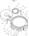
- Fig. 1 is a schematic configuration diagram showing an automatic analyzer according to a present embodiment.
- the automatic analyzer includes a sample storing unit 101, a reagent storing unit 102, a reaction unit 103, stirring units 104 to 109, an analyzing unit 110, a cleaning unit 111, a sample dispensing mechanism 113, and a reagent dispensing mechanism 115.
- the automatic analyzer further includes a control unit (host computer) that is configured by an electronic circuit or a storage device, and the operation of each of the units and each of the mechanisms is controlled by the control unit.
- a control unit host computer
- a sample container such as a test tube is stored, and the sample container contains a sample 112.
- the reaction unit 103 is configured by a rotatable reaction disk, and reaction containers 114 (reaction cells) are arranged on the reaction disk in a circumferential pattern.
- the reaction disk includes a constant temperature bath that holds constant-temperature water at a designated temperature, and by bringing the constant-temperature water circulating in the constant temperature bath into contact with the reaction containers 114, the reaction containers 114 are kept at the prescribed temperature.
- the sample dispensing mechanism 113 aspirates a necessary amount of the sample 112 for analysis from the inside of the sample container, and discharges the aspirated sample 112 into the reaction container 114 on the reaction unit 103.
- the reagent dispensing mechanism 115 aspirates a necessary amount of a reagent 116 for analysis from the reagent storing unit 102, and discharges the aspirated reagent 116 into the reaction container 114.
- the plurality of stirring units 104 to 109 are provided on the outer circumferential side of the reaction disk, and each of the stirring units 104 to 109 stirs the sample 112 and the reagent 116 discharged into the reaction container 114.
- the analyzing unit 110 executes component analysis of a reaction liquid obtained by the progress of the reaction of the sample 112 and the reagent 116 by measuring an absorbance of the reaction liquid.
- the cleaning unit 111 cleans the reaction container 114 after completion of the measurement of the absorbance. The next sample 112 is discharged by the sample dispensing mechanism 113 into the reaction container 114 cleaned by the cleaning unit 111, and subsequently the same sequence is repeated.
- the stirring units 104 to 109 realize the stirring of the sample 112 and the reagent 116 in a non-contact manner using vibrations, acoustic flows, acoustic radiation pressure, or the like by irradiating the reaction container 114 with ultrasonic waves.
- the stirring of the sample 112 and the reagent 116 is efficiently executed, and a high processing capacity is realized.
- liquid that mediates acoustic waves constant-temperature water is used.
- water other than constant-temperature water may also be used, and a liquid other than water may also be used.
- acoustic waves other than ultrasonic waves may also be used.
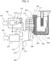
- Fig. 2 is a diagram that shows configurations of the stirring unit, and the power amplifier and the impedance measuring unit which are connected to the stirring unit.
- Fig. 2 shows a cross-section of the stirring unit 104 in the vertical direction along a radial direction of the sample storing unit 101, and shows a schematic configuration of an electrical circuit that is arranged on the host computer side with respect to the connector 201.
- the stirring unit 104 will be described as an example, but the same description can be applied to the stirring units 105 to 109.
- the stirring unit 104 includes a piezoelectric element 202 that generates ultrasonic waves, a jig 203 for attaching the piezoelectric element 202 to a constant temperature bath 117, a reflector 223 that reflects the ultrasonic waves transmitted through the reaction container 114 or the like toward the reaction container 114, and the connector 201 that electrically connects the piezoelectric element 202 and the host computer side.
- the piezoelectric element 202 includes: segmented electrodes 204 and 209 that are provided on one surface (air side surface) to be in contact with the air; and a constant-temperature water side electrode 205 that is provided on another surface (constant-temperature water side surface) to be in contact with constant-temperature water 208. A part of the constant-temperature water side electrode 205 is folded to the air side surface along a lower end surface of the piezoelectric element 202.
- the segmented electrodes 204 and 209 are segmented into a plurality of electrodes at different height positions.
- 13 segmented electrodes are provided ( Fig. 2 or the like shows only a part of the segmented electrodes)
- the number of the segmented electrodes is not limited to 13.
- the dimensions and shapes of the segmented electrodes can be individually freely designed.
- all of the first to twelfth segmented electrodes 204 have the same shape (the same width and length), and only the thirteenth (lowermost) segmented electrode 209 is formed to be slightly longer than the other segmented electrodes 204.
- Each of the segmented electrodes is connected one-to-one to each of pins of the connector 201.
- a power amplifier 206 applies a voltage to the segmented electrodes such that the piezoelectric element 202 is driven to generate ultrasonic waves.
- the power amplifier 206 includes a function generating circuit 210 that generates a drive waveform, a final stage amplifier circuit 211 that amplifies the waveform to a desired power, and a current monitor 212 that measures a current flowing through the piezoelectric element 202 during the voltage application.
- the current monitor 212 can be configured to use, for example, electromagnetic coupling.
- an impedance measuring circuit 207 measures frequency characteristics of electric impedance of the piezoelectric element 202 (hereinafter, also abbreviated as "ImpS").
- the ImpS of the piezoelectric element 202 is represented by a set including the ImpS of the respective segmented electrodes (that is, the ImpS between the segmented electrodes 204 and 209 and the constant-temperature water side electrode 205).
- a first interface unit 221 that connects the host computer is provided, and the host computer controls the power amplifier 206 through the first interface unit 221.
- a second interface unit 222 that connects the host computer is provided, and the host computer controls the impedance measuring circuit 207 through the second interface unit 222.
- the impedance measuring circuit 207 transmits the measurement result of the ImpS to the host computer through the second interface unit 222.
- the power amplifier 206 and the impedance measuring circuit 207 are connected to the stirring unit 104 through the connector 201. Further, relays 213 are arranged between the power amplifier 206 and the impedance measuring circuit 207, and the connector 201.
- the relays 213 include a plurality of switches, and control the opening and closing of each of the switches based on an instruction from the host computer. That is, the relays 213 function as a switching device that switches connection between the power amplifier 206 and the impedance measuring circuit 207, and the segmented electrodes 204 and 209.
- the host computer detects a liquid level position (liquid level height) of the liquid in the reaction container 114 (a specific example of a detection method will be described below). Further, the host computer selects one or more of the segmented electrodes 204 and 209 at appropriate positions according to the liquid level position, and controls the relays 213 such that a voltage is applied to the selected segmented electrodes 204 and 209. This way, the irradiation position of the reaction container 114 with the ultrasonic waves is adjusted.
- a liquid level position liquid level height
- a first changeover switch 215 that switches between the connection of the piezoelectric element 202 to the power amplifier 206 and the connection of the piezoelectric element 202 to the impedance measuring circuit 207 is provided between the power amplifier 206 and the impedance measuring circuit 207, and the relays 213.
- a second changeover switch 214 that switches between the connection of the impedance measuring circuit 207 to the piezoelectric element 202 and the connection of the impedance measuring circuit 207 to the ground is provided between the impedance measuring circuit 207 and the connector 201.
- the first changeover switch 215 is connected to a terminal 216 of the power amplifier 206, and the second changeover switch 214 is connected to a terminal 219 (is finally connected to a ground 220).
- the first changeover switch 215 is connected to an output terminal 217 of the impedance measuring circuit 207, and the second changeover switch 214 is connected to an input terminal 218 of the impedance measuring circuit 207.
- the host computer applies a voltage to each of the segmented electrodes 204 and 209 through the power amplifier 206, and measures the ImpS of the piezoelectric element 202 through the impedance measuring circuit 207.
- the impedance measuring circuit 207 does not need to be configured to be independent from the host computer as shown in Fig. 2 , and the impedance measuring circuit 207 and the host computer may be integrated and configured by a single electronic circuit.
- Fig. 3 is a diagram that shows details of a configuration of the impedance measuring circuit 207.
- a direct digital synthesizer (hereinafter, abbreviated as "DDS") 301 generates a sine wave voltage having any frequency.
- the sine wave voltage generated by the DDS 301 is amplified by an amplifier 302 and is output from the output terminal 217.
- the output terminal 217 is connected to the segmented electrodes 204 through the first changeover switch 215 and the relays 213, and the segmented electrodes 204 apply the sine wave voltage to the piezoelectric element 202.
- the magnitude of the applied voltage can be appropriately designed depending on the characteristics and the like of the piezoelectric element 202.
- a voltage during the ImpS measurement to be a voltage (for example, a voltage called a weak voltage) lower than that during the stirring operation, the breakage of the piezoelectric element 202 can be prevented.
- a current flowing through the piezoelectric element 202 during the voltage application flows to the input terminal 218 through the constant-temperature water side electrode 205 and the relays 213, and is detected as a voltage value by a detection resistor 305.
- the voltage signal detected by the detection resistor 305 is further amplified by a logarithmic amplifier 307 (LogAmp) through an operational amplifier 306 that linearly amplifies the signal with an appropriate gain.
- the voltage that is applied from the output terminal 217 to the piezoelectric element 202 is input to a micro control unit (hereinafter, abbreviated as "MCU") 310 through a wiring 308.
- MCU micro control unit
- the voltage amplified by the logarithmic amplifier 307 is input to the MCU 310 through a wiring 309.
- the logarithmic amplifier 307 is used.
- a linear amplifier may also be used instead of the logarithmic amplifier.
- the voltage signal input to the MCU 310 undergoes A/D conversion.
- the MCU 310 transmits a control signal 311 to the DDS 301 and sweeps the frequency of the generated sine wave in a desired frequency range.
- the frequency at this time, the applied voltage from the output terminal 217, and a measured voltage corresponding to the current flowing through the piezoelectric element 202 are stored in a memory in the MCU 310, and are transmitted as the ImpS measurement result to the host computer through the second interface unit 222.
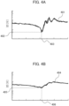
- Fig. 4A is an example of the result of ImpS measurement of the piezoelectric element 202 in the air
- Fig. 4B is an example of the result of ImpS measurement with one side of the piezoelectric element 202 in contact with the constant-temperature water.
- the horizontal axis represents the drive frequency
- the vertical axis represents an absolute value
- of the ImpS is a minimum value 402 is a resonance frequency 403 of the piezoelectric element 202.
- a phase difference at the resonance frequency 403 is substantially zero, and this resonance frequency 403 refers to a point at which the piezoelectric element 202 changes from the capacitive property to the inductive property.
- the piezoelectric element 202 further vibrates as compared to a case where the piezoelectric element 202 is driven at another frequency, and is in a resonant state in a thickness direction of the piezoelectric element 202.
- a resonance frequency 406 is not substantially different from the resonance frequency 403.
- of the electric impedance at the resonance frequency in Fig. 4B that is, a minimum value 405 of the absolute value
- a specific acoustic impedance of water to air is 3000 times or more, and when the acoustic impedance is high, an acoustic load increases, and the electric impedance increases correspondingly. That is, it is considered that Fig. 4B shows a state where the vibration of the surface of the piezoelectric element 202 in contact with the constant-temperature water propagates to the constant-temperature water and the ultrasonic waves are irradiated from the surface of the piezoelectric element 202.
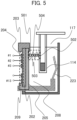
- Fig. 5 shows the influence of a standing wave between the reaction container 114 and the piezoelectric element 202.
- the ultrasonic waves generated by applying a voltage to the piezoelectric element 202 propagate to the constant-temperature water 208, and propagate up to the reaction container 114 as a traveling wave 501.
- the ultrasonic waves that reach the reaction container 114 are substantially totally reflected from an inner surface 502 of the reaction container 114 to generate a reflected wave 503. That is, between the inner surface 502 of the reaction container 114 and the piezoelectric element 202, the traveling wave 501 and the reflected wave 503 are combined to generate a standing wave 504.
- the ultrasonic waves have a property in which reflection does not occur in a uniform material, in other words, a property in which reflection occurs at a material boundary between different materials. Accordingly, the ultrasonic waves are substantially totally reflected at a material boundary having a significantly large difference in acoustic impedance between water and air.
- the ultrasonic waves reach the reaction container 114 through the constant-temperature water as a liquid. Therefore, the magnitude of the standing wave 504 largely varies depending on whether or not a liquid is present in the reaction container 114.
- the ID numbers of the segmented electrodes 204 and 209 of the piezoelectric element 202 are allocated with 1, 2, ..., 13 in order from the top, respectively, the electric impedances thereof are measured, and the magnitudes of the influences of the standing wave in the segmented electrodes 204 and 209 are measured. As a result, the liquid level height in the reaction container 114 can be measured.
- Fig. 6 is a graph that shows the frequency characteristics of electric impedance when a liquid is present at a position of a segmented electrode and when a liquid is not present at the position.
- the horizontal axis represents the frequency
- the vertical axis represents the absolute value of the electric impedance.
- the ImpS measured by the segmented electrode (for example, the ID number 1) at a height where the liquid is not present in the reaction container 114, has some poles due to the influence of the standing wave as indicated by a dotted line 601 in Fig. 6 , and it can be seen that the variation is large.
- the ImpS measured by the segmented electrode (for example, the ID number 13) at a height where the liquid is present in the reaction container 114 has a few poles as indicated by a solid line 602 in Fig. 6 , and it can be seen that the variation is small.
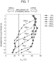
- Fig. 7 is a graph that shows the relation between Esw and the ID number of each segmented electrode when the amount of water in the reaction container 114 changes (0 ⁇ L, 45 ⁇ L, 90 ⁇ L, 135 ⁇ L, 180 ⁇ L, 225 ⁇ L).
- the Esw draws a curve that varies depending on the amount of water present in the reaction container 114.
- a predetermined threshold X is predetermined by the relationship between the Esw of each of the segmented electrodes and the amount of water in the reaction container 114. Therefore, by presuming that water is not present at a height of the segmented electrode where the Esw exceeds the threshold X, the height of the liquid level in the reaction container 114 can be detected.
- a connection condition between the stirring units 104 to 109 and the power amplifier 206 or the impedance measuring circuit 207, for example, whether or not the connector 201 is erroneously inserted is determined based on whether or not a liquid in the reaction container 114 can be detected.
- Fig. 8 is a schematic view that shows a case where the stirring units 104 and 105 are normally connected to relay boards 802 and 804, and
- Fig. 9 is a schematic view that shows a case where the stirring units 104 and 105 are not normally connected to relay boards 802 and 804.
- the relay board 802 provided in the relays corresponding to the stirring unit 104 is normally connected to the stirring unit 104 through a wiring 803.
- the relay board 804 provided in the relays corresponding to the stirring unit 105 is normally connected to the stirring unit 105 through a wiring 805. This way, each of the stirring units, each of the relay boards, and each of the wirings are connected by an appropriate combination. Therefore, a desired stirring operation can be executed.
- the relay board 802 provided in the relays corresponding to the stirring unit 104 may be erroneously connected to the stirring unit 105 through the wiring 803 due to a wiring connection mistake or the like during device assembly.
- an ultrasonic wave stirring operation set depending on dispensing parameters or the like is not executed when the desired reaction container 114 is stirred, which may adversely affect the analysis result due to insufficient stirring.
- a strong voltage is applied, which may also cause the breakage of the stirring unit 104 due to empty discharge.
- the control unit causes the cleaning unit 111 to discharge deionized water into a specific reaction container 114 (hereinafter, the reaction container will be referred to as a reference cell 801). At this time, it is necessary to make sure that deionized water or a liquid such as a sample or a reagent is not present in the reaction containers 114 other than the reference cell 801.
- control unit rotates a reaction disk 810 to move the reference cell 801 to a stirring position of the stirring unit 104.
- the control unit checks the liquid level height in the reference cell 801 using the above-described method. At this time, the liquid level height is detected as long as there is no erroneous insertion of the connector 201 and the relay board 802 and the stirring unit 104 are correctly connected through the wiring 803. On the other hand, when the erroneous insertion of the connector 201 occurs, the liquid level height is not detected.
- the liquid level height is also checked at stirring positions of the stirring units 105 to 109.
- the height of deionized water in the reference cell 801 can be determined even without using all of the segmented electrodes, the height of deionized water may be determined using a part of the segmented electrodes.
- the reference cell 801 may contain a liquid other than deionized water. Further, a method of detecting only whether or not a liquid is present instead of the liquid level height may also be used.
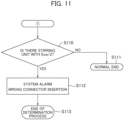
- Figs. 10 and 11 are flowcharts that show a method for determining whether the connector 201 is correctly inserted into the stirring units 104 to 109, Fig. 10 shows a part (first half) of the flowchart, and Fig. 11 shows the remaining part (latter half) of the flowchart.
- Step S101 the control unit of the automatic analyzer starts an abnormality determination operation.
- the control unit checks the water level of the constant temperature bath 117 (Step S102).
- a method of checking the water level not only a method using a water level sensor mounted on the automatic analyzer but also the method of detecting the liquid level based on the ImpS measured by the impedance measuring circuit 207 as described above may also be used.
- Step S103 When the constant temperature bath 117 does not reach a predetermined water level, the control unit outputs a system alarm and ends the abnormality determination operation (Step S103). On the other hand, when the constant temperature bath 117 reaches the predetermined water level, the control unit discharges deionized water into the reference cell 801 using the cleaning unit 111 (Step S104) . Dispensing parameters when deionized water is discharged into the reference cell 801 are stored in the control unit. The amount of deionized water discharged into the reference cell 801 can be freely set in a range where the amount can be measured by each of the stirring units.
- Step S105 the control unit rotates the reaction disk 810 to a prescribed angle that is preset.
- the reaction disk 810 rotates counterclockwise.
- the control unit derives the Esw of the reference cell 801 using each of the segmented electrodes of the stirring unit 104 (Step S106) .
- the Esw is derived in all of the segmented electrodes (ID numbers 1 to 13) of the piezoelectric element 202.
- the Esw may also be derived using only a part of the segmented electrodes.
- the control unit outputs a system alarm and ends the abnormality determination operation (Step S107) .
- the control unit stores the derived Esw (Step S108), and determines whether or not the derivation of the Esw is completed in all of the stirring units (Step S109). At this stage, the derivation of the Esw is not completed in the stirring units other than the stirring unit 104. Therefore, the control unit returns to Step S105, and in order to move the reference cell 801 to the stirring position of the next stirring unit 105, rotates the reaction disk 810 to a prescribed angle that is preset.
- the control unit checks whether or not Esw exceeding the prescribed value (threshold Z) that is preset is present among the Esws (Esw1, Esw2, Esw3, Esw4, Esw5, and Esw6) measured at stirring positions of the stirring units 104 to 109 (Step S110).
- the control unit can determine that the liquid level of the deionized water in the reference cell 801 can be normally detected at the stirring positions of all the stirring units. Therefore, the abnormality determination operation normally ends (Step S111).
- the control unit can determine that the liquid level of the deionized water in the reference cell 801 cannot be normally detected at the stirring positions of all the stirring units. Therefore, there is a possibility that the connector 201 may be erroneously inserted. Accordingly, in this case, the control unit outputs a system error (Step S112), displays the stirring unit that satisfies Esw > Z, and ends the determination operation (Step S113) .
- the control unit determines an inclination condition of the automatic analyzer according to a liquid level height of the constant-temperature water as detected in each of the stirring units.
- the weight of the automatic analyzer is biased. Therefore, there is a possibility that, in a placement location of the automatic analyzer, a floor corresponding to a heavy portion may be depressed such that an inclination occurs in the automatic analyzer.
- the liquid level height in the constant temperature bath 117 or the reaction container 114 varies depending on locations, and there is also a possibility that liquid leakage may occur or the stirring operation cannot be executed according to set parameters.
- the control unit detects the water level of the constant-temperature water in some different locations, and determines the inclination of the constant temperature bath 117 based on whether or not the difference between the water levels of the locations is within a prescribed value.
- Fig. 12 is a view that shows the water level of constant-temperature water at the time of determining the inclination of the constant temperature bath 117.
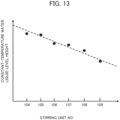
- the control unit derives the Esw at this time using each of the segmented electrodes 204 and 209 of the stirring units 104 to 109. Further, the control unit compares the derived Esw and the threshold X to each other using the above-described method and detects the liquid level height in each of the stirring units.
- Fig. 13 is a graph that shows the liquid level height of the constant-temperature water in each of the stirring units. As shown in Fig. 13 , a relationship between the position of the stirring unit and the liquid level height of the constant-temperature water can be approximated using a linear function. When the inclination of the linear function is within a preset range, that is, the lower limit value ⁇ the inclination of the linear function ⁇ the upper limit value is satisfied, the inclination of the constant temperature bath 117 is within a tolerance. Therefore, the control unit determines that there is no problem.
- the control unit outputs a system alarm.
- the abnormality detection described in the first example and the second example is executed, for example, when the automatic analyzer is installed, when the stirring unit is replaced, or when maintenance is regularly executed.
- the automatic analyzer may be executed every start-up.
- the present invention is not limited to each of the embodiments and includes various modification examples.
- each of the embodiments has been described in detail in order to easily describe the present invention, and the present invention does not necessarily include all the configurations described above.
- a part of the configuration of one embodiment can be replaced with the configuration of another embodiment.
- the configuration of one embodiment can be added to the configuration of another embodiment. Addition, deletion, and replacement of another configuration can be made for a part of the configuration of each of the embodiments.
Landscapes
- Chemical & Material Sciences (AREA)
- General Health & Medical Sciences (AREA)
- Life Sciences & Earth Sciences (AREA)
- Health & Medical Sciences (AREA)
- Analytical Chemistry (AREA)
- Biochemistry (AREA)
- Physics & Mathematics (AREA)
- General Physics & Mathematics (AREA)
- Immunology (AREA)
- Pathology (AREA)
- Engineering & Computer Science (AREA)
- Quality & Reliability (AREA)
- Chemical Kinetics & Catalysis (AREA)
- Automatic Analysis And Handling Materials Therefor (AREA)
Applications Claiming Priority (2)
| Application Number | Priority Date | Filing Date | Title |
|---|---|---|---|
| JP2021175576 | 2021-10-27 | ||
| PCT/JP2022/037922 WO2023074358A1 (fr) | 2021-10-27 | 2022-10-11 | Dispositif d'analyse automatisé et procédé de détermination d'anomalie associé |
Publications (2)
| Publication Number | Publication Date |
|---|---|
| EP4425185A1 true EP4425185A1 (fr) | 2024-09-04 |
| EP4425185A4 EP4425185A4 (fr) | 2025-10-22 |
Family
ID=86157922
Family Applications (1)
| Application Number | Title | Priority Date | Filing Date |
|---|---|---|---|
| EP22886687.7A Pending EP4425185A4 (fr) | 2021-10-27 | 2022-10-11 | Dispositif d'analyse automatisé et procédé de détermination d'anomalie associé |
Country Status (5)
| Country | Link |
|---|---|
| US (1) | US20240402200A1 (fr) |
| EP (1) | EP4425185A4 (fr) |
| JP (1) | JP7649873B2 (fr) |
| CN (1) | CN118043673A (fr) |
| WO (1) | WO2023074358A1 (fr) |
Family Cites Families (6)
| Publication number | Priority date | Publication date | Assignee | Title |
|---|---|---|---|---|
| JP2007040843A (ja) | 2005-08-03 | 2007-02-15 | Hitachi High-Technologies Corp | 自動分析装置 |
| JP2007248413A (ja) * | 2006-03-20 | 2007-09-27 | Toshiba Corp | 自動分析装置及びその水平出し方法 |
| CN101755213B (zh) * | 2007-07-18 | 2013-05-08 | 贝克曼考尔特公司 | 分析装置及其异常处理方法 |
| JP2010096638A (ja) * | 2008-10-17 | 2010-04-30 | Hitachi High-Technologies Corp | 自動分析装置 |
| JP7474644B2 (ja) | 2020-06-18 | 2024-04-25 | 株式会社日立ハイテク | 自動化学分析装置および電気インピーダンススペクトル測定器 |
| JP7665406B2 (ja) | 2021-05-18 | 2025-04-21 | 株式会社日立ハイテク | 自動化学分析装置、自動化学分析装置用メンテナンスキット、及び自動化学分析装置のメンテナンス方法 |
-
2022
- 2022-10-11 CN CN202280064976.8A patent/CN118043673A/zh active Pending
- 2022-10-11 JP JP2023556292A patent/JP7649873B2/ja active Active
- 2022-10-11 WO PCT/JP2022/037922 patent/WO2023074358A1/fr not_active Ceased
- 2022-10-11 EP EP22886687.7A patent/EP4425185A4/fr active Pending
- 2022-10-11 US US18/698,402 patent/US20240402200A1/en active Pending
Also Published As
| Publication number | Publication date |
|---|---|
| WO2023074358A1 (fr) | 2023-05-04 |
| CN118043673A (zh) | 2024-05-14 |
| JPWO2023074358A1 (fr) | 2023-05-04 |
| JP7649873B2 (ja) | 2025-03-21 |
| US20240402200A1 (en) | 2024-12-05 |
| EP4425185A4 (fr) | 2025-10-22 |
Similar Documents
| Publication | Publication Date | Title |
|---|---|---|
| US12510553B2 (en) | Automatic chemical analysis apparatus and electrical impedance spectrometry device | |
| EP4342577A1 (fr) | Analyseur chimique automatique, kit de maintenance d'analyseur chimique automatique et procédé de maintenance d'analyseur chimique automatique | |
| EP1261876B1 (fr) | Systeme permettant de verifier la surface d'un fluide et de la distribution d'un fluide | |
| JPH04218726A (ja) | 容量性液体境界面センサ | |
| US9863905B2 (en) | Method for detecting contact of a pipetting needle | |
| CN101952693A (zh) | 检测移液管状态的方法,吸移方法,吸移设备和吸移设备的吸入管 | |
| EP0694784A1 (fr) | Collecteur d'échantillons liquides | |
| EP2180324A1 (fr) | Dispositif de détermination de brassage, procédé de détermination de brassage, et analyseur | |
| EP4425185A1 (fr) | Dispositif d'analyse automatisé et procédé de détermination d'anomalie associé | |
| CN114761811A (zh) | 化学分析装置 | |
| JP2009031203A (ja) | 自動分析装置 | |
| EP4664088A1 (fr) | Procédé de détection d'anomalie pour vibreur à ultrasons | |
| JP6224371B2 (ja) | 自動分析装置 | |
| JP7301764B2 (ja) | 自動分析装置 | |
| EP4459290A1 (fr) | Appareil et procédé d'analyse chimique | |
| EP4450975A1 (fr) | Dispositif d'analyse automatisé | |
| JPH08146011A (ja) | 自動化学分析装置 |
Legal Events
| Date | Code | Title | Description |
|---|---|---|---|
| STAA | Information on the status of an ep patent application or granted ep patent |
Free format text: STATUS: THE INTERNATIONAL PUBLICATION HAS BEEN MADE |
|
| PUAI | Public reference made under article 153(3) epc to a published international application that has entered the european phase |
Free format text: ORIGINAL CODE: 0009012 |
|
| STAA | Information on the status of an ep patent application or granted ep patent |
Free format text: STATUS: REQUEST FOR EXAMINATION WAS MADE |
|
| 17P | Request for examination filed |
Effective date: 20240527 |
|
| AK | Designated contracting states |
Kind code of ref document: A1 Designated state(s): AL AT BE BG CH CY CZ DE DK EE ES FI FR GB GR HR HU IE IS IT LI LT LU LV MC ME MK MT NL NO PL PT RO RS SE SI SK SM TR |
|
| DAV | Request for validation of the european patent (deleted) | ||
| DAX | Request for extension of the european patent (deleted) | ||
| REG | Reference to a national code |
Ref country code: DE Ref legal event code: R079 Free format text: PREVIOUS MAIN CLASS: G01N0035000000 Ipc: B06B0001020000 |
|
| A4 | Supplementary search report drawn up and despatched |
Effective date: 20250922 |
|
| RIC1 | Information provided on ipc code assigned before grant |
Ipc: B06B 1/02 20060101AFI20250916BHEP Ipc: B06B 1/06 20060101ALI20250916BHEP Ipc: G01N 35/00 20060101ALI20250916BHEP Ipc: G01N 35/02 20060101ALI20250916BHEP |