EP4428071A1 - Procédé et système de commande synchronisée - Google Patents
Procédé et système de commande synchronisée Download PDFInfo
- Publication number
- EP4428071A1 EP4428071A1 EP23382212.1A EP23382212A EP4428071A1 EP 4428071 A1 EP4428071 A1 EP 4428071A1 EP 23382212 A EP23382212 A EP 23382212A EP 4428071 A1 EP4428071 A1 EP 4428071A1
- Authority
- EP
- European Patent Office
- Prior art keywords
- passage
- substrate
- drive
- transport
- position signal
- Prior art date
- Legal status (The legal status is an assumption and is not a legal conclusion. Google has not performed a legal analysis and makes no representation as to the accuracy of the status listed.)
- Pending
Links
Images




Classifications
-
- B—PERFORMING OPERATIONS; TRANSPORTING
- B65—CONVEYING; PACKING; STORING; HANDLING THIN OR FILAMENTARY MATERIAL
- B65G—TRANSPORT OR STORAGE DEVICES, e.g. CONVEYORS FOR LOADING OR TIPPING, SHOP CONVEYOR SYSTEMS OR PNEUMATIC TUBE CONVEYORS
- B65G49/00—Conveying systems characterised by their application for specified purposes not otherwise provided for
- B65G49/05—Conveying systems characterised by their application for specified purposes not otherwise provided for for fragile or damageable materials or articles
- B65G49/06—Conveying systems characterised by their application for specified purposes not otherwise provided for for fragile or damageable materials or articles for fragile sheets, e.g. glass
-
- B—PERFORMING OPERATIONS; TRANSPORTING
- B41—PRINTING; LINING MACHINES; TYPEWRITERS; STAMPS
- B41J—TYPEWRITERS; SELECTIVE PRINTING MECHANISMS, i.e. MECHANISMS PRINTING OTHERWISE THAN FROM A FORME; CORRECTION OF TYPOGRAPHICAL ERRORS
- B41J11/00—Devices or arrangements of selective printing mechanisms, e.g. ink-jet printers or thermal printers, for supporting or handling copy material in sheet or web form
- B41J11/008—Controlling printhead for accurately positioning print image on printing material, e.g. with the intention to control the width of margins
-
- B—PERFORMING OPERATIONS; TRANSPORTING
- B41—PRINTING; LINING MACHINES; TYPEWRITERS; STAMPS
- B41J—TYPEWRITERS; SELECTIVE PRINTING MECHANISMS, i.e. MECHANISMS PRINTING OTHERWISE THAN FROM A FORME; CORRECTION OF TYPOGRAPHICAL ERRORS
- B41J11/00—Devices or arrangements of selective printing mechanisms, e.g. ink-jet printers or thermal printers, for supporting or handling copy material in sheet or web form
- B41J11/007—Conveyor belts or like feeding devices
-
- B—PERFORMING OPERATIONS; TRANSPORTING
- B41—PRINTING; LINING MACHINES; TYPEWRITERS; STAMPS
- B41J—TYPEWRITERS; SELECTIVE PRINTING MECHANISMS, i.e. MECHANISMS PRINTING OTHERWISE THAN FROM A FORME; CORRECTION OF TYPOGRAPHICAL ERRORS
- B41J2/00—Typewriters or selective printing mechanisms characterised by the printing or marking process for which they are designed
- B41J2/005—Typewriters or selective printing mechanisms characterised by the printing or marking process for which they are designed characterised by bringing liquid or particles selectively into contact with a printing material
- B41J2/01—Ink jet
-
- B—PERFORMING OPERATIONS; TRANSPORTING
- B41—PRINTING; LINING MACHINES; TYPEWRITERS; STAMPS
- B41J—TYPEWRITERS; SELECTIVE PRINTING MECHANISMS, i.e. MECHANISMS PRINTING OTHERWISE THAN FROM A FORME; CORRECTION OF TYPOGRAPHICAL ERRORS
- B41J3/00—Typewriters or selective printing or marking mechanisms characterised by the purpose for which they are constructed
- B41J3/407—Typewriters or selective printing or marking mechanisms characterised by the purpose for which they are constructed for marking on special material
-
- B—PERFORMING OPERATIONS; TRANSPORTING
- B65—CONVEYING; PACKING; STORING; HANDLING THIN OR FILAMENTARY MATERIAL
- B65G—TRANSPORT OR STORAGE DEVICES, e.g. CONVEYORS FOR LOADING OR TIPPING, SHOP CONVEYOR SYSTEMS OR PNEUMATIC TUBE CONVEYORS
- B65G49/00—Conveying systems characterised by their application for specified purposes not otherwise provided for
- B65G49/05—Conveying systems characterised by their application for specified purposes not otherwise provided for for fragile or damageable materials or articles
- B65G49/06—Conveying systems characterised by their application for specified purposes not otherwise provided for for fragile or damageable materials or articles for fragile sheets, e.g. glass
- B65G49/063—Transporting devices for sheet glass
- B65G49/064—Transporting devices for sheet glass in a horizontal position
Definitions
- the present invention relates to a synchronised drive method and system for substrate processing devices, such as panels, wherein the substrates are displaced relative to the processing devices by a means of transport, such as a conveyor belt or a roller conveyor.
- the present invention is particularly applicable to the industry of substrate digital printing, likewise relating to a digital printing machine that comprises a synchronised drive system.
- Synchronised drive methods and systems for substrate processing devices that use a position signal obtained by encoders are currently well known.
- the position signal provides a position associated with the displacement of the substrates at each instant.
- Rotary encoders are used in the means of transport made up of a conveyor belt or a roller conveyor.
- the rotary encoders are functionally coupled to the rotation shaft of a conveyor belt feed roller or of a roller conveyor. These encoders provide an angular position of said rotation shaft, which is related to the position of the displacement of the substrate and/or of the means of transport.
- the processing device To drive the processing device synchronously with the displacement of a substrate, the processing device is driven when the position associated with the displacement, provided by the position signal, from a positioning point through which the substrate passes, takes a given drive position value.
- This drive position value is predetermined in correspondence with the distance between the positioning point and a drive point at which the processing device should perform the action on the substrate.
- synchronised drive methods and systems have the disadvantage that they do not allow optimal precision when performing the synchronised action on the substrate, either due to a delay or an advance with respect to the instant of nominal implementation and/or a mislocation with respect to the nominal location on the substrate of the performed action, which can occur erroneously.
- an improvement in synchronisation precision in the known substrate digital inkjet printing methods and systems is desirable.
- This improvement in synchronisation precision has a direct impact on an improvement in print resolution. This is due to the fact that increasing the number of pixels per print area or per unit length along the direction of displacement of the substrate, in order to obtain higher print resolution at a given printing speed, requires higher synchronisation precision to avoid delays or advances in the instant of ejection of the print drops and/or mislocations of the ejected drops on the substrate.
- Patent document WO 2021/146595 A1 discloses a synchronised drive system for substrate processing devices that are displaced by means of a conveyor belt for substrate digital printing.
- the system incorporates an improved encoder compared to purely rotary encoders, comprising an encoder strip moved by two rollers and positioned in contact on the conveyor belt.
- this encoder has the drawback of its constructive complexity which is transferred to the system.
- the present invention provides a synchronised drive method for at least one substrate processing device when the substrate is displaced by a means of transport.
- the method comprises: obtaining a position signal by means of an encoder, said signal providing a position associated with the displacement of the substrate and/or means of transport at each instant; and driving a processing device when the position provided by the position signal from a positioning point through which the substrate passes takes a given drive position value.
- the method further comprises: measuring, and/or obtaining data on, physical and/or kinematic characteristics of the substrate and/or of the means of transport related to displacement; and correcting the position signal and/or the drive position value, based on the measurement or data obtained, to drive the processing device.
- the processing device is driven when the position from the positioning point provided by the corrected position signal takes the uncorrected drive position value and/or when the position from the positioning point provided by the uncorrected position signal takes the corrected drive position value.
- Position associated with the displacement of the substrate and/or means of transport is understood to be, in particular, a position of a mobile element, in particular, of the substrate and/or means of transport, such as the substrate itself, the band of a conveyor belt, the rotation shaft corresponding to a feed roller of the band, the rotation shaft of a roller of a roller conveyor, etc., such that it is related to the position of the substrate and/or means of transport in its displacement.
- the position associated with the displacement is provided by a position signal generated by a position encoder, in a manner known per se.
- the encoder is functionally coupled to said mobile element, which movement is related to the displacement of the substrate and/or means of transport.
- the encoder can be, for example, linear or rotary.
- a rotary encoder can be used that is functionally coupled to the rotation shaft of a feed roller of the band or of a conveyor roller, which makes it possible to obtain a position signal that provides a position associated with the displacement through the angular position of the rotation of said shaft.
- the uncorrected drive position value is a predetermined value that corresponds to the value of the position provided by the uncorrected position signal from the positioning point so that the processing device may be driven when the substrate has been displaced a fixed distance from said point.
- the uncorrected drive position value can be obtained from said relationship constituted by, for example, a theoretical function, such as a kinematic function, which relates the variation of the position provided by the position signal to the distance of displacement of the substrate between two points.
- the position signal and/or the drive position value are corrected. Synchronisation precision can be increased by means of the correction, since the correction makes it possible to take into account factors that have an effect on the actual displacement of the substrate and/or means of transport which are not considered if an uncorrected position signal and an uncorrected drive value are used like in the state of the art.
- the applicant has observed that, for example, in the event that the means of transport is made up of a conveyor belt, having a rotary encoder functionally coupled to the rotation shaft of a feed roller of the band, there can be, in particular, both slippage between the shaft and encoder and/or between the band and roller and/or between the substrate and band, as well as deformations of the band itself, which introduce precision errors that are not taken into account in the methods of the state of the art.
- behaviours depend on the utilisation scheme of the system, in particular, for example, on the substrate load, displacement speed, continuous operation time, etc. For this reason, it is not possible to take such behaviour into account with the synchronised drive methods of the state of the art, since the drive position value remains constant. Unlike the synchronised drive methods of the state of the art, in the present invention said behaviours can be taken into account by being able to dynamically vary the correction of the position signal and/or of the drive position value during the use of the system.
- the present invention also relates to a synchronised drive system for at least one processing device of a substrate that is displaced relative to the devices by a means of transport.
- the system is configured to perform a synchronised drive method as described herein. In this sense, everything indicated for the synchronised drive method according to the invention is applicable to the system and vice versa.
- the system comprises: means for measuring, and/or obtaining data on, physical and/or kinematic characteristics of the substrate and/or of the means of transport related to the displacement; and a control device that is operationally connected to an encoder to obtain a position signal, to means for detecting the passage of the substrates through a positioning point, to the means for measuring, and/or obtaining data on, physical and/or kinematic characteristics of the substrate and/or of the means of transport related to the displacement, and to the processing devices.
- the means for detecting the passage of the substrates through a positioning point comprise, in particular, at least one detection sensor for detecting the passage of a reference element fixed to the substrate.
- the reference element may be attached to, or integrated into, the substrate itself, in particular, forming part of the substrate. It is contemplated, for example, that the reference element is made up of the leading edge of the substrate according to the direction of its displacement.
- the detection sensor can be, for example, a contrast detection sensor, in a manner known per se.
- the control device is configured to carry out the synchronised drive method according to the invention.
- the control device comprises, in particular, at least one programmable device, for example, with FPGA programmable logic, and/or software.
- processing devices used in the present invention can be any type of device that is used to perform an action on a substrate that is displaced.
- measuring devices, coating devices, cutting devices, stamping devices, engraving devices, digital printing devices, etc. of the substrate can be considered processing devices.
- the present invention applies to processing devices that are digital inkjet printing devices that are part of, and in particular constitute, an inkjet printer, more particularly a single-pass inkjet printer.
- processing devices that are digital inkjet printing devices that are part of, and in particular constitute, an inkjet printer, more particularly a single-pass inkjet printer.
- Digital printing devices comprise a plurality of print heads, which have a plurality of ink ejection nozzles arranged aligned along a direction perpendicular to displacement.
- digital printing devices are configured to eject drops with a volume less than or equal to 20 pL, preferably 10 pL, more preferably 5 pL, and/or to provide print resolution in the direction perpendicular to displacement greater than or equal to 360 dpi, preferably 720 dpi, more preferably 1200 dpi. This resolution is determined by the physical distance between ejection nozzles arranged in the print heads.
- the present invention also relates to a substrate digital printing machine comprising: an inkjet printer, in particular, a single-pass inkjet printer, which comprises the printing devices; a means of transport to displace the substrates to be printed by the inkjet printer; an encoder to obtain the position signal; and means for detecting the passage of the substrates through a positioning point.
- the substrate digital printing machine comprises a synchronised drive system for the digital printing devices as described, for the synchronised drive of the digital printing devices of the substrates (S) as they are displaced by the means of transport.
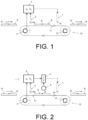
- Figure 1 shows a known synchronised drive method and system for synchronising a processing device (1) of a panel-shaped substrate (S), which is displaced by a means of transport (10), as shown in the figure, from left to right.
- the means of transport is made up of a conveyor belt (10) comprising a band (11) or belt that supports the substrate (S) in its displacement, which moves in a closed circuit being fed by two feed rollers.
- a drive motor (12) is coupled to the shaft of one of the feed rollers (11) of the band and an encoder (3) is coupled to the shaft of the other feed roller.
- a position signal ( s 0 ) is obtained by means of the encoder (3), said signal providing a position associated with the displacement of the substrate (S) and/or means of transport (10) at each instant, consisting of an angular position of the rotation of the shaft of the feed roller of the band (11) to which the encoder (3) is coupled, which is related to the displacement of the substrate (S) and of the band (11).
- the processing device (1) is driven at the drive point (Pi) when said angular position from a positioning point (Pp), through which a reference element (R) of the substrate (S) passes, takes a given drive position value ( V 0 ).
- the passage of the reference element (R) through the positioning point (Pp) is detected by a detection sensor (2) for detecting the reference element (R).
- the angular position is provided by the position signal ( s 0 ).
- the position signal ( s 0 ) and the drive position value ( V 0 ) are processed in a position obtaining module (4), which is part of a control device of the system.
- the position obtaining module (4) of the processing device is operationally connected to the processing device (1), to the detection sensor (2) and to the encoder (3), to carry out the synchronised drive method of the substrate (S) by the processing device (1).
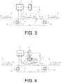
- the method comprises: measuring, and/or obtaining data on, physical and/or kinematic characteristics of the substrate (S) and/or of the means of transport (10) related to the displacement; and correcting the position signal ( s 0 ; s ) and/or the drive position value ( V 0 ; V ) based on the measurement or data obtained, to drive the processing device (1).
- the uncorrected position signal ( s 0 ), obtained from the encoder (3), and/or the uncorrected drive position value ( V 0 ), processed in the position obtaining module (4) of the control device, are corrected to obtain the corrected position signal ( s ) and/or the corrected drive position value (V).
- This correction is carried out in a position correction module (5) which, together with the position obtaining module (4), is part of a control device of the system.
- the position obtaining module (4) and position correction module (5) of the control device are operationally connected to each other and to the processing device (1), to the detection sensor (2), to the encoder (3) and to means for measuring (2.1, 2.2; 7), and/or means for obtaining data (6) on, physical and/or kinematic characteristics of the substrate (S) and/or of the means of transport (10) related to the displacement, to carry out the synchronised drive method of the substrate (S) by means of the processing device (1).
- the means for obtaining data on physical and/or kinematic characteristics of the substrate (S) and/or of the means of transport (10) related to displacement comprise, for example, a data log (6) for storing and/or processing said data.
- the means for measuring physical and/or kinematic characteristics of the substrate (S) and/or of the means of transport (10) related to displacement comprise, for example, a measurement sensor (7) such as, for example, a speed sensor for the band (11) and/or for the substrate (S) when passing through a measurement point (Pm).
- a measurement sensor (7) such as, for example, a speed sensor for the band (11) and/or for the substrate (S) when passing through a measurement point (Pm).
- any type of sensor can be used to measure, for example, physical characteristics, such as the weight of the substrate, or other kinematic characteristics, such as the acceleration, of the band and/or of the substrate (S) at the measurement point (Pm).
- the measurements and/or data obtained are used to correct the position signal ( s 0 ; s ), or the drive position value ( V 0 ; V), in the position correction module (5) of the system control device.
- the correction can be carried out, for example, based on a modification or adjustment of the theoretical relationship between the position associated with the displacement, which is obtained by the encoder (3), and the real position of the displacement of the substrate (S) and/or band (11) of the means of transport (10).
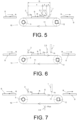
- the method according to the invention comprises obtaining a variation ( ⁇ ) in the position between a previous point of passage (Pa) and a subsequent point of passage (Ps), position which is provided by the uncorrected position signal ( s 0 ), by detecting the passage of a reference element (R; Q, Q'), fixed to the substrate (S) and/or to the means of transport (10), in particular to the band (11), through said points of passage (Pa, Ps).
- the correction of the position signal ( s 0 ; s ) and/or of the drive position value ( V 0 ; V) is carried out based on said variation ( ⁇ ).
- this variation ( ⁇ ) in the position can be used to estimate the displacement speed of the band (11) between the previous point of passage (Pa) and subsequent point of passage (Ps), so that a constant nominal speed that determines the uncorrected drive position value ( V 0 ) can be adjusted and thereby obtain the corrected drive position value (7).
- the means for measuring physical and/or kinematic characteristics of the substrate (S) and/or of the means of transport (10) related to displacement comprise, for example, at least one detection sensor (2, 2.1, 2.2; 2.3; 2.4) for detecting the passage, through the points of passage (Pa, Ps), of a reference element (R; Q; Q') fixed to the substrate (S) and/or to the means of transport (10), in particular to the band (11) of the conveyor belt (10).
- Obtaining the variation ( ⁇ ) in the position between the points of passage (Pa, Ps) is carried out by means of a position variation obtaining module (8) that is part of the system control device.
- This module (8) is operationally connected to the detection sensors (2, 2.1, 2.2, 2.3, 2.4), to the position obtaining module (4) and to the position correction module (5).
- the position variation obtaining module (8) acquires the position, provided by the uncorrected position signal ( s 0 ), of the position obtaining module (4), for the instant at which the reference element (R; Q; Q'), of the substrate (S) and/or of the means of transport (10), passes through respective points of passage (Pa, Ps), which is detected by the respective detection sensors (2, 2.1, 2.2, 2.3, 2.4).
- This same module (8) calculates the variation ( ⁇ ) by subtracting the position of the previous point of passage (Pa) from the position of the subsequent point of passage (Ps).
- the variation ( ⁇ ) is transferred to the position correction module (5) in order to, based on same, correct the position signal ( s 0 ; s ) and/or the drive position value ( V 0 ; V), which is communicated to the processing device (1) for its synchronised drive at the drive point (Pi).
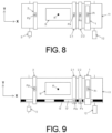
- the correction of the position signal ( s 0 ; s ) and/or of the drive position value ( V 0 ; V) based on the variation ( ⁇ ) comprises obtaining a difference ( ⁇ ) between a reference variation value ( ⁇ o) of the position between the points of passage (Pa, Ps) and the variation ( ⁇ ) in the measured position, such that the corrected position signal ( s ) is obtained by adding the difference ( ⁇ ) to the uncorrected position signal ( s 0 ) and/or the corrected drive position value ( V ) is obtained by subtracting the difference ( ⁇ ) from the uncorrected drive position value ( V 0 ).
- Obtaining the difference ( ⁇ ) can be carried out in the position variation obtaining module (8), as shown, in particular, in Figure 4 .
- the difference ( ⁇ ) calculated by the module (8) between the reference variation value ( ⁇ o) and the variation ( ⁇ ) in the measured position is transferred to the position correction module (5) in order to, based on same, correct the position signal ( s 0 ; s ) and/or the drive position value ( V 0 ; V), which is communicated to the processing device (1) for its synchronised drive at the drive point (Pi).
- This embodiment according to the invention wherein the correction of the position signal ( s 0 ; s ) and/or of the drive position value ( V 0 ; V) is carried out by a difference ( ⁇ ) applied directly (by addition or subtraction) to the uncorrected position signal ( s 0 ) and/or to the uncorrected drive position value ( V 0 ), in addition to its simple implementation, has the advantage that the introduction of calculation errors in its treatment is minimised, as it does not require additional mathematical operations other than addition or subtraction.
- the reference variation value ( ⁇ 0 ) can be obtained, for example, theoretically by means of a theoretical function, in particular a kinematic function, that relates the variation of the position associated with the displacement, obtained by means of the uncorrected position signal ( s 0 ), with the distance between the points of passage (Pa, Ps).
- a theoretical function in particular a kinematic function, that relates the variation of the position associated with the displacement, obtained by means of the uncorrected position signal ( s 0 ), with the distance between the points of passage (Pa, Ps).
- the same theoretical or kinematic function that is used to calculate the uncorrected drive position value ( V 0 ) for the distance between the positioning point and the drive device (1), for example, the drive point (Pi) can be used.
- the reference variation value ( ⁇ 0 ), as well as the uncorrected drive position value ( V 0 ), represent the incremental position values that, for an ideal behaviour of the system (without slippage or deformations that cause precision errors in the synchronisation), would correspond exactly to the distance between the points at which the position is detected, in other words, between the previous point (Pa) and the subsequent point (Ps) for the reference variation value ( ⁇ 0 ), and between the positioning point (Pp) and the drive point (Pi) for the drive position value ( V 0 ).
- the synchronised drive method and system according to the invention is capable of capturing the error to be corrected.
- distance between points is understood to generally refer to the distance in a direction of displacement or a straight or curvilinear path of displacement.
- the direction of displacement is the direction indicated by the X-axis (see Figures 8, 9 , 17 and 18 ).
- the previous point of passage (Pa) is arranged substantially close to or not distant from the positioning point (Pp) and/or the subsequent point of passage (Ps) or the measurement point (Pm) is arranged substantially close to or not distant from the processing device (1; 1.1, 1.2, 1.3), in particular from the drive point (Pi).
- the previous point of passage (Pa) is arranged after the positioning point (Pp) and/or the subsequent point of passage (Ps) is arranged before the processing device (1).
- the correction for each substrate (S) can be carried out in real time, after the passage of the reference element (R) of the substrate through the subsequent point of passage (Ps) and before the drive at the drive point (Pi).
- substantially close positioning, measurement, passage or drive points is understood to mean that the respective measuring means, in particular detection sensors, or processing devices are arranged physically and substantially adjacent along the direction or path of displacement and/or that the distance between them is not substantially greater than the distance necessary so that, due to electronic processing constraints of the control device, it allows time to apply the corrected position signal ( s ) and/or the corrected drive position value ( V ) to the processing device (1) after the reference element (R) of the substrate (S) has passed through the subsequent point of passage (Ps).
- the distance (e) between the subsequent point of passage (Ps) and the processing device (1), in particular the drive point (Pi), can be less than 10% of the distance (D) between the positioning point (Pp) and the processing device (1) or the drive point (Pi), preferably less than 5%, more preferably less than 1%.
- the distance (c) between the positioning point (Pp) and the previous point of passage (Pa) can be less than 10% of the distance (D) between the positioning point (Pp) and the processing device (1) or the drive point (Pi), preferably less than 5%, more preferably less than 1%.
- the proximity of the previous points of passage to the positioning point and the subsequent points of passage to the drive point makes it possible to maximise the distance (d) between the points of passage (Pa, Ps) and therefore the length of location of synchronisation errors along the displacement, substantially spanning the entire length of displacement of the substrate (S) from the positioning to the drive.
- the coincidence of the points makes it possible to use the same detection sensor for them.
- FIG 6 an embodiment is represented in which the previous point of passage (Pa) is not distant from the positioning point (Pp).
- Figure 7 another embodiment is represented in which the previous point of passage (Pa) is not distant from the subsequent point of passage (Ps).
- This embodiment of Figure 7 can be applied, for example, in systems such as the one represented in which a point of the band (11) passes through the same point (Pa,s) several times.
- the invention is applicable, for example, to conveyor belts (10) with bands (11) displaced in a closed circuit, as shown in the figures, or to conveyor belts in which the band itself moves forwards and backwards passing through the same point.
- FIGS 8 and 9 show details of the system in plan view. These figures show particular arrangements and shapes of the reference elements (R; Q, Q').
- the represented panel-shaped substrate (S) incorporates a reference element (R) on its upper surface; this reference element (R) is detected by the detection sensor (2) as it passes through the positioning point (Pp), by the detection sensor (2.1) as it passes through the previous point of passage (Pa) and by the detection sensor (2.2) as it passes through the subsequent point of passage (Ps).
- the figures show that the reference element (R) used to detect its passage through the points of passage (Pa, Ps) is the same reference element (R) as the one used to detect its passage through the positioning point (Pp).
- these reference elements (R) may be different elements or may be arranged in different locations on the substrate (S).
- the substrate (S) and/or the means of transport (10, 11, 12), in particular the band (11) of a conveyor belt (10), comprises a plurality of reference elements (R; Q, Q').
- R; Q, Q' reference elements
- the plurality of reference elements (Q; Q') are part of a reference pattern (Q, Q'), fixed to the substrate (S) and/or to the means of transport (10), particularly to the band (11).
- the arrangement of the reference elements (Q; Q') forming a reference pattern (Q, Q') allows the reliability of the measurements to be increased by enabling more precise control of the arrangement, dimensions, distances, etc. of the reference elements that make up the pattern.
- the band (11) incorporates a reference pattern (Q, Q') formed in this case by consecutive black (Q) and white (Q') strips that extend over the upper surface of the band (11), on one side of it and along its entire length according to the length of displacement.
- the reference element (Q; Q') is the flank of each strip, where the white-black colour change occurs.
- the detection sensors (2.1, 2.2) are contrast detection sensors that detect the change in white-black colour and therefore the reference element (Q; Q') as it passes through the points of passage (Pa, Ps).
- the substrate (S) incorporates a reference element (R) that is detected by the detection sensor (2) as it passes through the positioning point (Pp), as in the embodiment of Figure 8 .
- the reference elements and reference patterns applicable to the invention may have any shape, configuration or arrangement.
- the reference elements (R, Q, Q') can be fixed to, attached to, or integrated into the substrate (S) itself, in particular by forming part of the substrate, or the means of transport (10), in particular in (or on) the band (11) of a conveyor belt (10).
- the reference elements of the reference patterns can be formed by motifs different from each other, for example, formed by consecutive letters or numbers.
- the choice of different reference elements in reference patterns makes it easier to differentiate between them when determining the specific reference element that passes through the subsequent point of passage (Ps) having passed through the previous point of passage (Pa).
- the method according to the invention comprises storing data associated with the measurement, for example, by means of the control device memory.
- the method comprises storing the position associated with the displacement, the variation ( ⁇ ) and/or the difference ( ⁇ ), for different substrates (S) and/or for different reference elements (R; Q, Q') of the substrate (S) or of the means of transport (10), so that the correction of the position signal ( s 0 ; s ) and/or of the drive position value ( V 0 ; V) is carried out based on a selection of said data, in particular, by means of a FIFO method ("First In, First Out").
- a FIFO method First In, First Out
- the uncorrected position signal ( s 0 ) and corrected position signal ( s ) are pulse signals.
- the position or the variation ( ⁇ ) in the position can be easily obtained by counting the number of pulses (p, p') of the signal ( s 0 , s ).
- the uncorrected pulse signal ( s 0 ) is obtained directly from the encoder, which encodes the position associated with the displacement.
- the processing of the position signals as pulse signals ( s 0 ; s ) allows its use for continuous synchronisation as a clock signal for the processing devices, as is done in digital printing.
- the corrected position signal ( s ) is obtained by introducing or suppressing pulses (p, p') in the uncorrected position signal ( s 0 ), which makes it possible to correct the position signal ( s 0 ; s ) in a simple manner.
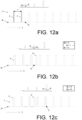
- Figure 10a represents the uncorrected pulse signal (p) ( s 0 ), obtained from the encoder (3). It is a signal with period T.
- the instant at which the reference element (R) passes through the positioning point (Pp) is represented as tp.
- the same figure represents the instant at which the reference element (R) passes through the previous point of passage (Pa).
- the dashed line indicates the signal that has not elapsed yet.
- Figure 10b represents the pulse signal ( s 0 ; s ).
- the reference element (R) passes through the subsequent point of passage (Ps), which is represented as ts.
- V 0 6 i.e., six pulses counted from tp.
- the instant at which the processing device (1) is driven at the drive point (Pi) is represented in Figure 10c as ti.
- the processing device (1) is driven at the drive point (Pi) later than in the case represented in Figures 10a to 10c , at instant ti, delaying the performance of the action and thus increasing synchronisation precision.
- the processing device (1) is driven at the drive point (Pi) earlier than in the case represented in Figures 10a to 10c , at instant ti, bringing forward the performance of the action and thus increasing synchronisation precision.
- the correction of the position signal ( s 0 ; s ) and/or of the drive position value ( V 0 ; V) is carried out when the position from the positioning point (Pp), provided by the uncorrected position signal ( s 0 ), takes a predetermined correction position value ( V c ).
- this position value represents the moment at which the pulses (p, p') required for its correction are introduced into or suppressed from the uncorrected position signal.
- this correction position value ( V c ) can be selected as a value close to and/or less than the predetermined drive position value ( V 0 ).
- Proximate is understood to mean that the absolute value of the difference between the drive position value ( V 0 ) and correction position value ( V c ) is small compared to the drive position value ( V 0 ) and large enough to give time to correct the position signal ( s 0 ; s ) and/or the drive position value ( V 0 ; V).
- Figures 13 to 18 show different embodiments of the method and system according to the invention that comprise a plurality of processing devices (1.1, 1.2, 1.3), with their respective drive points (Pi, Pi', Pi"; Pii, Piii).
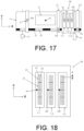
- FIGs 17 and 18 show a digital printing machine that comprises a synchronised drive system in which the processing devices are digital inkjet printing devices (1.1, 1.2, 1.3).
- the digital printing devices are part of an inkjet printer (20), in particular a single-pass inkjet printer.
- Each digital printing device (1.1, 1.2, 1.3) comprises a plurality of print heads (21), each print head (21) having a plurality of ink ejection nozzles (22) arranged aligned along a direction (Y-axis) perpendicular to the direction of displacement (X-axis). It is contemplated that each digital printing device (1.1, 1.2, 1.3) corresponds to a print colour.
- the resolution of the print heads (21) along the Y-axis is determined by the distance (g) between ejection nozzles (22), so that in the configuration shown in Figure 18 the resolution is determined by half the distance (g) between nozzles.
- the system comprises a plurality of consecutive processing devices (1.1, 1.2, 1.3) that are associated with a single pair of points of passage (Pa, Ps).
- This configuration makes it possible to optimise the measuring means and the available space, especially when it is not possible to have detection sensors inserted between the processing devices (1.1, 1.2, 1.3).
- the processing devices (1.1, 1.2, 1.3) are arranged between the points of passage (Pa, Ps).
- the drive of the processing devices is carried out by means of a common corrected position signal ( s ') and/or a common corrected drive position value ( V ').
- the system control device comprises a position obtaining module (4), a position correction module (9) and a position variation obtaining module (8), in a similar way to when there is only one processing device (1).
- These modules (4, 8, 9) are operationally connected to each other, to the measurement means, in particular detection sensors (2.5, 2.6), and to the processing devices (1.1, 1.2, 1.3) to apply the synchronised drive method according to the invention.
- the common correction of the position signal ( s 0 , s ') can be carried out, for example, by a rated correction, such that the difference ( ⁇ ) is applied in a distributed manner along the length of displacement of the substrate as it passes through the processing devices.
- a number of pulses per unit length are introduced or suppressed based on the value of the measured difference ( ⁇ ) and the distance (f) between the points of passage (Pa, Ps) and between the points of passage and processing devices (f1, f2, f3, f4).
- the common correction of the drive position value ( V 0 ; V' ) can be carried out by a rated correction, so that the drive position value ( V ') is dynamically modified by applying the difference ( ⁇ ) in a distributed manner along the length of displacement of the substrate as it passes through the processing devices.
- the rated correction of the position signal ( s 0 , s ') and/or of the drive position value ( V 0 ; V') is carried out when the position from the positioning point (Pp), provided by the uncorrected position signal ( s 0 ), takes a predetermined initial correction position value ( V ci ) and until it takes a predetermined final correction position value ( V cf ) .
- this range of correction position values ( V ci , V cf ) represents the period of time in which the pulses (p, p') required for its correction are introduced into, or suppressed from, the uncorrected position signal in a distributed manner.
- the drive of the processing devices is carried out by means of respective corrected position signals ( s A , s B , s C ) and/or respective corrected drive position values ( V A , V B , V C ).
- the system control device comprises a position obtaining module (4), a position correction module (9') and a position variation obtaining module (8), in a similar way to when there is only one processing device (1).
- These modules (4, 8, 9') are operationally connected to each other, to the measurement means, in particular the detection sensors (2.5, 2.6), and to the processing devices (1.1, 1.2, 1.3) to apply the synchronised drive method according to the invention.
- the correction of the position signal ( s 0 , s A , s B , s C ) can be carried out, for example, by means of a weighted correction, so that the difference ( ⁇ ) is applied in a timely manner along the length of displacement of the substrate as it passes through the processing devices (1.1, 1.2, 1.3) but in a weighted way for each of the processing devices (1.1, 1.2, 1.3).
- a certain number of pulses are introduced or suppressed based on the value of the measured difference ( ⁇ ) and the distance (f) between the points of passage (Pa, Ps) and between the points of passage and processing devices (f1, f2, f3, f4).
- the system comprises a plurality of consecutive processing devices (1.2, 1.3) which are associated with respective pairs of points of passage (Par, Ps'; Par, Ps"), in which the previous point of passage (Par) and/or the subsequent point of passage (Ps', Ps") is shared.
- the previous point of passage (Par) corresponding to the last two processing devices (1.2, 1.3) is shared.
- This configuration makes it possible to optimise the measurement means and the available space, while allowing the insertion of measurement means, such as detection sensors (2.8, 2.9), in particular points of passage (Ps', Ps"), more in particular a single point of passage, between processing devices (1.2, 1.3).
- the system control device comprises a position obtaining module (4), respective position correction modules (5.1, 5.2, 5.3) and respective position variation obtaining modules (8.1, 8.2), in a similar way to when there is only one processing device (1).
- These modules (4, 5.1, 5.2, 5.3, 8.1, 8.2) are operationally connected to each other, to the measurement means, in particular detection sensors (2.7, 2.8, 2.9), and to the processing devices (1.1, 1.2, 1.3) to apply the synchronised drive method according to the invention.
- the previous point of passage (Pa; Par) is arranged substantially close to or not distant from a preceding processing device (1.1) to at least one processing device (1.2; 1.3), more particularly, it is arranged before said preceding processing device (1.1).
- This configuration is fulfilled both in the embodiment of Figures 13 to 15 and in the embodiment of Figure 16 , since it is the preceding processing device (1.1), i.e., arranged before the other processing devices (1.2, 1.3). With this configuration, a drive of the following processing devices (1.2, 1.3) is achieved with respect to the preceding processing device (1.1), regardless of the synchronisation errors that would affect the very preceding processing device (1.1).
Landscapes
- Control Of Conveyors (AREA)
- Control Of Position Or Direction (AREA)
- Ink Jet (AREA)
- Controlling Sheets Or Webs (AREA)
Priority Applications (5)
| Application Number | Priority Date | Filing Date | Title |
|---|---|---|---|
| EP23382212.1A EP4428071A1 (fr) | 2023-03-07 | 2023-03-07 | Procédé et système de commande synchronisée |
| PCT/ES2024/070097 WO2024184561A1 (fr) | 2023-03-07 | 2024-02-20 | Procédé et système d'actionnement synchronisé |
| JP2025552324A JP2026510368A (ja) | 2023-03-07 | 2024-02-20 | 同期された駆動方法及びシステム |
| KR1020257029770A KR20250163314A (ko) | 2023-03-07 | 2024-02-20 | 동기화 구동 방법 및 시스템 |
| CN202480017303.6A CN120826319A (zh) | 2023-03-07 | 2024-02-20 | 同步驱动方法及系统 |
Applications Claiming Priority (1)
| Application Number | Priority Date | Filing Date | Title |
|---|---|---|---|
| EP23382212.1A EP4428071A1 (fr) | 2023-03-07 | 2023-03-07 | Procédé et système de commande synchronisée |
Publications (1)
| Publication Number | Publication Date |
|---|---|
| EP4428071A1 true EP4428071A1 (fr) | 2024-09-11 |
Family
ID=85778666
Family Applications (1)
| Application Number | Title | Priority Date | Filing Date |
|---|---|---|---|
| EP23382212.1A Pending EP4428071A1 (fr) | 2023-03-07 | 2023-03-07 | Procédé et système de commande synchronisée |
Country Status (5)
| Country | Link |
|---|---|
| EP (1) | EP4428071A1 (fr) |
| JP (1) | JP2026510368A (fr) |
| KR (1) | KR20250163314A (fr) |
| CN (1) | CN120826319A (fr) |
| WO (1) | WO2024184561A1 (fr) |
Citations (4)
| Publication number | Priority date | Publication date | Assignee | Title |
|---|---|---|---|---|
| US20080030536A1 (en) * | 2006-08-07 | 2008-02-07 | Fujifilm Corporation | Image recording apparatus and image recording method |
| JP2016182694A (ja) * | 2015-03-25 | 2016-10-20 | セイコーエプソン株式会社 | 液体吐出装置及び液体吐出方法 |
| US10596828B2 (en) * | 2017-09-19 | 2020-03-24 | Shibaura Mechatronics Corporation | Tablet printing apparatus and tablet printing method |
| WO2021146595A1 (fr) | 2020-01-16 | 2021-07-22 | Electronics For Imaging, Inc. | Codeur rotatif linéaire |
Family Cites Families (5)
| Publication number | Priority date | Publication date | Assignee | Title |
|---|---|---|---|---|
| IT1269386B (it) * | 1994-06-29 | 1997-03-26 | Syfal Srl | Apparecchiatura per l'alimentazione sincronizzata di piastrelle ceramiche ad una macchina rotativa per decorazione-smaltatura |
| US6374075B1 (en) * | 2000-04-28 | 2002-04-16 | Xerox Corporation | Printing systems and methods |
| JP2009078376A (ja) * | 2007-09-25 | 2009-04-16 | Seiko Epson Corp | 画像形成装置及びパルス生成方法 |
| US8863661B2 (en) * | 2011-03-11 | 2014-10-21 | Ohio Gravure Technologies, Inc. | System and method for layer-to-layer compensation and error correction |
| CN112437750B (zh) * | 2019-05-13 | 2022-10-28 | 埃斯科绘图成像有限责任公司 | 用于印版的输送系统和方法 |
-
2023
- 2023-03-07 EP EP23382212.1A patent/EP4428071A1/fr active Pending
-
2024
- 2024-02-20 CN CN202480017303.6A patent/CN120826319A/zh active Pending
- 2024-02-20 KR KR1020257029770A patent/KR20250163314A/ko active Pending
- 2024-02-20 WO PCT/ES2024/070097 patent/WO2024184561A1/fr not_active Ceased
- 2024-02-20 JP JP2025552324A patent/JP2026510368A/ja active Pending
Patent Citations (4)
| Publication number | Priority date | Publication date | Assignee | Title |
|---|---|---|---|---|
| US20080030536A1 (en) * | 2006-08-07 | 2008-02-07 | Fujifilm Corporation | Image recording apparatus and image recording method |
| JP2016182694A (ja) * | 2015-03-25 | 2016-10-20 | セイコーエプソン株式会社 | 液体吐出装置及び液体吐出方法 |
| US10596828B2 (en) * | 2017-09-19 | 2020-03-24 | Shibaura Mechatronics Corporation | Tablet printing apparatus and tablet printing method |
| WO2021146595A1 (fr) | 2020-01-16 | 2021-07-22 | Electronics For Imaging, Inc. | Codeur rotatif linéaire |
Also Published As
| Publication number | Publication date |
|---|---|
| CN120826319A (zh) | 2025-10-21 |
| WO2024184561A1 (fr) | 2024-09-12 |
| JP2026510368A (ja) | 2026-04-02 |
| KR20250163314A (ko) | 2025-11-20 |
Similar Documents
| Publication | Publication Date | Title |
|---|---|---|
| JP6418491B2 (ja) | 記録手段吐出位置調整装置及び画像形成装置 | |
| US20080180476A1 (en) | Printing Apparatus, Printing Method, Program, Storage Medium, and Computer System | |
| USRE48785E1 (en) | Ink jet recorder | |
| JP5055826B2 (ja) | 画像記録装置 | |
| EP2633996B1 (fr) | Procédé et dispositif de commande de position d'impression par jet d'encre | |
| JP5128240B2 (ja) | 画像形成装置 | |
| JP2007301768A (ja) | 画像記録装置 | |
| JP2007069428A (ja) | インクジェット記録装置 | |
| EP4428071A1 (fr) | Procédé et système de commande synchronisée | |
| JP5628565B2 (ja) | 印刷装置 | |
| JP6390958B2 (ja) | 記録手段吐出位置調整装置及び画像形成装置 | |
| US20220314604A1 (en) | Liquid discharge device, liquid discharge method, and program | |
| JP2020131516A (ja) | インクジェットプリンタ、インクジェットプリンタの吐出タイミング補正方法およびプログラム | |
| KR20230172406A (ko) | 인쇄제어장치, 인쇄제어방법, 인쇄제어프로그램 | |
| US7766443B2 (en) | Image forming apparatus, method of compensating for error of conveyance distance of recording medium in the same and computer readable medium provided in the same | |
| JP2013132758A (ja) | 記録装置および記録方法 | |
| US11772392B2 (en) | Base material processing apparatus and detection method | |
| JP2007283644A (ja) | 画像記録装置 | |
| JP2006192575A (ja) | 記録装置、液体噴射装置 | |
| JP4419508B2 (ja) | 画像記録装置 | |
| JP7155690B2 (ja) | 画像形成装置、画像形成方法、補正値算出プログラム、および補正値検出パターン。 | |
| JP4515734B2 (ja) | プリンタ装置の制御装置 | |
| JP6900778B2 (ja) | 記録装置 | |
| JPH04363277A (ja) | シリアルプリンタ | |
| JP5868037B2 (ja) | インクジェット記録装置およびインクジェット記録方法 |
Legal Events
| Date | Code | Title | Description |
|---|---|---|---|
| PUAI | Public reference made under article 153(3) epc to a published international application that has entered the european phase |
Free format text: ORIGINAL CODE: 0009012 |
|
| STAA | Information on the status of an ep patent application or granted ep patent |
Free format text: STATUS: THE APPLICATION HAS BEEN PUBLISHED |
|
| AK | Designated contracting states |
Kind code of ref document: A1 Designated state(s): AL AT BE BG CH CY CZ DE DK EE ES FI FR GB GR HR HU IE IS IT LI LT LU LV MC ME MK MT NL NO PL PT RO RS SE SI SK SM TR |
|
| STAA | Information on the status of an ep patent application or granted ep patent |
Free format text: STATUS: REQUEST FOR EXAMINATION WAS MADE |
|
| 17P | Request for examination filed |
Effective date: 20250307 |