EP4428100A1 - Procédé et dispositif pour la synthèse d'ammoniac - Google Patents
Procédé et dispositif pour la synthèse d'ammoniac Download PDFInfo
- Publication number
- EP4428100A1 EP4428100A1 EP23020117.0A EP23020117A EP4428100A1 EP 4428100 A1 EP4428100 A1 EP 4428100A1 EP 23020117 A EP23020117 A EP 23020117A EP 4428100 A1 EP4428100 A1 EP 4428100A1
- Authority
- EP
- European Patent Office
- Prior art keywords
- hydrogen
- ammonia
- synthesis
- water
- nitrogen
- Prior art date
- Legal status (The legal status is an assumption and is not a legal conclusion. Google has not performed a legal analysis and makes no representation as to the accuracy of the status listed.)
- Withdrawn
Links
Images

Classifications
-
- C—CHEMISTRY; METALLURGY
- C01—INORGANIC CHEMISTRY
- C01C—AMMONIA; CYANOGEN; COMPOUNDS THEREOF
- C01C1/00—Ammonia; Compounds thereof
- C01C1/02—Preparation, purification or separation of ammonia
- C01C1/04—Preparation of ammonia by synthesis
- C01C1/0405—Preparation of ammonia by synthesis from N2 and H2 in presence of a catalyst
-
- C—CHEMISTRY; METALLURGY
- C01—INORGANIC CHEMISTRY
- C01B—NON-METALLIC ELEMENTS; COMPOUNDS THEREOF; METALLOIDS OR COMPOUNDS THEREOF NOT COVERED BY SUBCLASS C01C
- C01B3/00—Hydrogen; Gaseous mixtures containing hydrogen; Separation of hydrogen from mixtures containing it; Purification of hydrogen; Reversible storage of hydrogen
- C01B3/02—Production of hydrogen; Production of gaseous mixtures containing hydrogen
- C01B3/025—Preparation or purification of gas mixtures for ammonia synthesis
-
- C—CHEMISTRY; METALLURGY
- C25—ELECTROLYTIC OR ELECTROPHORETIC PROCESSES; APPARATUS THEREFOR
- C25B—ELECTROLYTIC OR ELECTROPHORETIC PROCESSES FOR THE PRODUCTION OF COMPOUNDS OR NON-METALS; APPARATUS THEREFOR
- C25B1/00—Electrolytic production of inorganic compounds or non-metals
-
- C—CHEMISTRY; METALLURGY
- C25—ELECTROLYTIC OR ELECTROPHORETIC PROCESSES; APPARATUS THEREFOR
- C25B—ELECTROLYTIC OR ELECTROPHORETIC PROCESSES FOR THE PRODUCTION OF COMPOUNDS OR NON-METALS; APPARATUS THEREFOR
- C25B1/00—Electrolytic production of inorganic compounds or non-metals
- C25B1/01—Products
- C25B1/02—Hydrogen or oxygen
- C25B1/04—Hydrogen or oxygen by electrolysis of water
-
- C—CHEMISTRY; METALLURGY
- C25—ELECTROLYTIC OR ELECTROPHORETIC PROCESSES; APPARATUS THEREFOR
- C25B—ELECTROLYTIC OR ELECTROPHORETIC PROCESSES FOR THE PRODUCTION OF COMPOUNDS OR NON-METALS; APPARATUS THEREFOR
- C25B15/00—Operating or servicing cells
- C25B15/08—Supplying or removing reactants or electrolytes; Regeneration of electrolytes
Definitions
- the invention relates to a process for the synthesis of ammonia, in which an ammonia synthesis gas comprising hydrogen and nitrogen is formed in a synthesis circuit with the addition of anhydrous make-up hydrogen and is fed to an ammonia reactor in order to convert it with catalytic support into a synthesis product containing ammonia, hydrogen and nitrogen, which is separated into an ammonia-rich liquid phase and a gas phase consisting largely of hydrogen and nitrogen, at least a part of which is returned to the ammonia reactor via the synthesis circuit to form the ammonia synthesis gas, wherein a water-containing hydrogen fraction produced by electrochemical decomposition of water (electrolysis hydrogen) is provided to obtain the anhydrous make-up hydrogen.
- the invention relates to a device for carrying out the method according to the invention.
- Ammonia is one of the most widely produced chemicals in the world. It is primarily used as a raw material for the production of fertilizers, but is also becoming increasingly important as an energy source and hydrogen storage medium. On an industrial scale, it is synthesized almost exclusively from nitrogen and hydrogen using the Haber-Bosch process.
- an ammonia synthesis gas consisting mainly of hydrogen and nitrogen, in which the two substances are present in the stoichiometric ratio of 3:1 for the synthesis of ammonia, is fed to an ammonia reactor at a pressure of between 80 and 300 bar and a temperature of between 150 and 250°C in order to be converted with catalytic support in an exothermic reaction to form ammonia. Due to thermodynamic limitations, however, the conversion is only incomplete, so that a synthesis product is created which, in addition to ammonia, also contains considerable amounts of hydrogen and nitrogen.
- the synthesis product leaves the ammonia reactor at a temperature of between 400 and 450°C and is subsequently a series of heat exchangers, usually cooled to temperatures between -20 and 0°C, in order to separate ammonia by condensation and obtain a two-phase mixture of substances, which is separated in a subsequent separation device into a gas mixture consisting at least largely of hydrogen and nitrogen, containing residues of uncondensed ammonia, and a liquid phase consisting predominantly of ammonia.
- the liquid phase consisting predominantly of ammonia is usually further purified, enriched with a small amount of water to avoid stress corrosion, and stored as an ammonia product in steel containers at atmospheric pressure and a temperature of -33°C.
- the separation device comprises a high-pressure phase separator, which is operated at a pressure which essentially corresponds to the pressure in the ammonia reactor, and a medium-pressure separator, in which the ammonia-rich liquid phase obtained in the high-pressure phase separator is expanded to a pressure which is approximately as high as the pressure of the make-up gases (for example 30 bar) in order to obtain the liquid phase consisting largely of ammonia, which is further cooled and expanded to separate remaining impurities in order to obtain ammonia, which is released as a product after possible admixture of a small amount of water or is stored.
- a high-pressure phase separator which is operated at a pressure which essentially corresponds to the pressure in the ammonia reactor
- a medium-pressure separator in which the ammonia-rich liquid phase obtained in the high-pressure phase separator is expanded to a pressure which is approximately as high as the pressure of the make-up gases (for example 30 bar) in order to obtain the liquid phase consisting largely of ammonia, which is further
- the state of the art involves desulphurising a hydrocarbon-containing feedstock, such as natural gas, if necessary, and then converting it, for example, by steam reforming, partial oxidation or autothermal reforming, into a synthesis raw gas that consists largely of hydrogen, carbon monoxide and carbon dioxide and also contains water.
- the synthesis raw gas is then subjected to water gas conversion in order to convert the carbon monoxide it contains with water to hydrogen and carbon dioxide.
- Carbon dioxide is separated from the converted gas by acid gas scrubbing, among other things, resulting in a hydrogen fraction known as raw hydrogen, which, in addition to hydrogen, also contains residues of carbon monoxide and carbon dioxide as well as water.
- the raw hydrogen is further treated for this purpose, for example by methanation, nitrogen scrubbing or pressure swing adsorption, whereby carbon monoxide, carbon dioxide and free oxygen are converted or separated together with any water present.
- electrolysis hydrogen gas fraction
- electrolysis hydrogen does not contain carbon monoxide but is usually saturated with water.
- Electrolysis hydrogen also contains up to 1000 ppmv of free oxygen, so it cannot be used directly as make-up hydrogen.
- its free oxygen content may be reduced by separating oxygen and/or converting oxygen to water before it is freed of water, for example by pressure or temperature swing adsorption, which requires a high level of equipment and energy.
- the present invention has for its object to provide a method of the generic type and a device for carrying it out, which allow the effort for the synthesis of ammonia to be reduced compared to the prior art.
- the object is achieved in accordance with the invention in that the electrolysis hydrogen or a hydrogen fraction obtained from the electrolysis hydrogen by reducing free oxygen is reacted with at least part of the ammonia-rich liquid phase to separate water and obtain the anhydrous makeup hydrogen.
- free oxygen is separated from the electrolysis hydrogen and/or converted to water by reaction with hydrogen, so that the hydrogen fraction with an atomic oxygen concentration of less than 5 ppmv is obtained.
- the reduction of free oxygen can be omitted if the electrolysis hydrogen already has a free oxygen content of less than 5 ppmv.
- the invention makes use of the hygroscopic properties of liquid ammonia, which binds the water contained in the electrolysis hydrogen or in the hydrogen fraction obtained from electrolysis hydrogen by reducing free oxygen.
- the water therefore does not enter the ammonia reactor via the synthesis circuit or only in an amount that is not critical for the catalyst material used. Separation of water from the electrolysis hydrogen upstream of the synthesis circuit, as is necessary in the prior art, can therefore be dispensed with entirely or at least largely.
- the process according to the invention produces an ammonia product which has a low water content, which may already be sufficiently high to be able to store it in steel containers at atmospheric pressure without corrosion problems.
- the addition of water is therefore not necessary or only required to a significantly reduced extent compared to the prior art.
- the electrolysis hydrogen or the hydrogen fraction obtained from electrolysis hydrogen by reducing free oxygen via a feed device (sparger) into a bubble column in the bottom of which the ammonia-rich liquid phase is present.
- the gas phase advantageously exits through downward-facing openings into the ammonia-rich liquid phase, in which it rises upwards distributed in a large number of gas bubbles.
- the gas bubbles form a large phase interface, which ensures that water contained in the gas phase quickly attaches itself to the ammonia in the liquid phase and is effectively removed to levels below 10 ppmv.
- the gas phase which collects in the gas space of the bubble column and consists largely of hydrogen is preferably fed into the synthesis cycle to form the ammonia synthesis gas without any further processing step as anhydrous make-up hydrogen due to its low water or oxygen content, preferably below 10 ppmv.
- the bubble column is expediently operated at a pressure which, apart from line losses, corresponds to the pressure of the electrolysis hydrogen or the hydrogen fraction obtained from electrolysis hydrogen by reducing free oxygen (typically around 30 bar).
- the bubble column is used as a medium-pressure separator, in which an ammonia-rich condensate separated from the cooled synthesis product in a high-pressure separator at a higher pressure is released.
- the ammonia-rich condensate is preferably separated from the cooled synthesis product in the high-pressure separator at a pressure which, apart from line losses, corresponds to the pressure during ammonia synthesis.
- the electrolysis hydrogen or the hydrogen fraction obtained from electrolysis hydrogen by reducing free oxygen can also be treated in a washing column, whereby it is fed countercurrently to an ammonia-rich liquid phase fed to the top of the washing column and washed by this.
- the gas phase which consists largely of hydrogen and can be removed from the top of the washing column, is preferably fed to the synthesis circuit to form the ammonia synthesis gas without a further processing step as anhydrous make-up hydrogen due to its low water content, preferably below 10 ppmv.
- the washing column is expediently operated at a pressure which, apart from line losses, corresponds to the pressure of the electrolysis hydrogen or the hydrogen fraction obtained from electrolysis hydrogen by reducing free oxygen (typically about 30 bar).
- a pressure which, apart from line losses, corresponds to the pressure of the electrolysis hydrogen or the hydrogen fraction obtained from electrolysis hydrogen by reducing free oxygen (typically about 30 bar).
- the cooled synthesis product is separated in a high-pressure phase separator and a downstream medium-pressure separator and the ammonia-rich liquid phase obtained in the medium-pressure separator is fed to the top of the washing column as a scrubbing agent.
- the process according to the invention can be used advantageously when the electrolysis hydrogen or the hydrogen fraction obtained from electrolysis hydrogen by reducing free oxygen has a high water content.
- the electrolysis hydrogen or the hydrogen fraction obtained from electrolysis hydrogen by reducing free oxygen can be saturated with water.
- a preferred embodiment of the method according to the invention provides that at least part of the nitrogen required as make-up gas is mixed with the electrolysis hydrogen or the hydrogen fraction obtained from electrolysis hydrogen by reducing free oxygen into the synthesis product to be cooled. This is particularly advantageous if water-containing nitrogen is available to form the make-up nitrogen, as is obtained, for example, when a nitrogen fraction separated from air by pressure swing adsorption is subjected to catalytic deoxidation to remove free oxygen, in which free oxygen reacts to form water.
- make-up nitrogen partially or completely with the part of the gas phase consisting largely of hydrogen and nitrogen that is returned in the synthesis cycle or with the make-up hydrogen.
- the invention further relates to a device for the synthesis of ammonia, with an ammonia reactor which is integrated into a synthesis circuit in which an ammonia synthesis gas comprising hydrogen and nitrogen can be formed by supplying make-up hydrogen and fed to the ammonia reactor in order to be converted with catalytic support into a synthesis product containing ammonia, hydrogen and nitrogen, a cooling device which is connected to a separating device so that the synthesis product can be cooled and separated into an ammonia-rich liquid phase and a gas phase consisting largely of hydrogen and nitrogen, at least a part of which in the Synthesis circuit can be traced back to the ammonia reactor, as well as a hydrogen source connected to the synthesis circuit, which comprises an electrolyzer with which a water-containing hydrogen fraction (electrolysis hydrogen) can be provided by electrochemical decomposition of water to obtain the make-up hydrogen.
- an ammonia reactor which is integrated into a synthesis circuit in which an ammonia synthesis gas comprising hydrogen and nitrogen can be formed by
- the stated object is achieved according to the invention in that it comprises a contact apparatus connected to the hydrogen source and the synthesis circuit, to which electrolysis hydrogen or a hydrogen fraction obtainable from electrolysis hydrogen by reducing free oxygen can be fed in order to be brought into contact with at least part of the ammonia-rich liquid phase in order to separate water and to obtain the anhydrous make-up hydrogen.
- the contact apparatus is designed as a bubble column which has a feed device (sparger) via which the electrolysis hydrogen or the hydrogen fraction obtainable from electrolysis hydrogen by reducing free oxygen, divided into a large number of gas bubbles, can be introduced into the ammonia-rich liquid phase present in the bottom of the bubble column.
- a feed device separger
- the bubble column It is sensible for the bubble column to be designed simultaneously as a medium-pressure separator and, as part of the separation device, connected to a high-pressure phase separator with which an ammonia-rich condensate can be separated from the cooled synthesis product, which can then be expanded into the bubble column.
- the high-pressure phase separator can preferably be operated at a pressure which, apart from line losses, corresponds to the operating pressure of the ammonia reactor.
- the contact apparatus can also be designed as a washing column, to which ammonia-rich liquid phase from the high-pressure phase separator can be fed as a washing agent at the top.
- the washing column can be equipped with mass transfer trays and/or at least one structured packing, through which the electrolysis hydrogen or the hydrogen fraction obtainable from electrolysis hydrogen by reducing free oxygen can be fed in countercurrent to the washing agent.
- the contact apparatus is connected to the synthesis circuit via a feed device in such a way that the gas phase obtained by contact with the ammonia-rich liquid phase can be used as anhydrous make-up hydrogen to form the ammonia synthesis gas.
- the feed device is expediently connected to a mixing device with which at least part of the make-up nitrogen required in the synthesis circuit can be mixed with the make-up hydrogen.
- the hydrogen source can, for example, comprise an acidic or PEM electrolyzer or an alkaline electrolyzer or a solid oxide electrolyzer. Since such electrolyzers produce the electrolysis hydrogen with an oxygen concentration that is too high for make-up hydrogen, the hydrogen source in these cases in particular has an oxygen reduction with which the free oxygen content of the electrolysis hydrogen can be reduced to below 5 ppmv by separating oxygen and/or converting oxygen to water. Oxygen reduction is a catalytic deoxidation with which free oxygen can be converted to water with hydrogen over a catalyst bed.
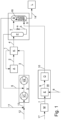
- FIGS 1 and 2 show ammonia syntheses which are operated according to preferred variants of the process according to the invention.
- the ammonia synthesis gas 1 produced in a synthesis cycle in which hydrogen and nitrogen are present in the stoichiometric ratio of 3:1 for the synthesis of ammonia, is fed to the ammonia reactor A in anhydrous form and at a temperature between 150 and 250°C, where it is converted with catalytic support in an exothermic reaction at a pressure between 80 and 300 bar to form ammonia to form the synthesis product 2, which contains not only ammonia but also considerable amounts of hydrogen and nitrogen.
- the synthesis product 2 which leaves the ammonia reactor A at a temperature between 400 and 480°C, is Cooling device K cools, among other things, ammonia synthesis gas 3 to be heated to a temperature between -20 and 0°C, whereby ammonia condenses out and a two-phase mixture 4 is formed, which is passed on to the separation device T.
- the two-phase mixture 4 is separated in the high-pressure phase separator P into a first ammonia-rich liquid phase 5 and a first gas phase 6 consisting largely of hydrogen and nitrogen.
- the first gas phase 6 is fed as high-pressure recycle gas to the high-pressure stage V2 of the circuit compressor V
- the first ammonia-rich liquid phase 5 is expanded via the throttle element a into the medium-pressure separator B, which is operated at a pressure of, for example, 30 bar and is designed as a bubble column, in order to separate dissolved gases, whereby dissolved hydrogen and nitrogen in particular pass into the gas phase and a second ammonia-rich liquid phase is formed, which collects in the sump space of the bubble column.
- the hydrogen discharged from the synthesis circuit with the second ammonia-rich liquid phase is replaced by anhydrous make-up hydrogen, for the production of which water is fed to the water treatment M via line 17 in order to be processed into demineralized water 7 and passed on to the electrolyzer E arranged in the hydrogen source W.
- the demineralized water 7 is decomposed with the aid of electrical current 8, which is preferably supplied from a renewable power source, producing electrolysis hydrogen 9, which is typically saturated with water and usually contains up to 1000 ppmv of free oxygen.
- the free oxygen content of the electrolysis hydrogen 9 is reduced to a value below 5 ppmv, which creates a hydrogen fraction 10 saturated with water, which is introduced via the sparger S into the second ammonia-rich liquid phase in the sump space of the bubble column B, which acts as a contact apparatus, in order to separate the water that is harmful to the catalyst material used in the ammonia reactor A. In this phase it rises distributed in a large number of gas bubbles.
- the first ammonia-rich liquid phase 5 obtained in the high-pressure phase separator P is expanded via the throttle element a into the medium-pressure separator B', which is not designed as a bubble column and is operated at a pressure of, for example, 30 bar, whereby dissolved hydrogen and nitrogen in particular pass into the gas phase, which is fed as medium-pressure recycle gas 7' in front of the inlet stage V1 of the circuit compressor V.
- the second ammonia-rich liquid phase 15 from the bottom of the medium-pressure separator B' is fed as a scrubbing agent to the top of the scrubbing column H, which acts as a contact apparatus, into the lower region of which the water-saturated hydrogen fraction 10 formed from the electrolysis hydrogen 9 by reducing free oxygen is introduced.
- the water-saturated hydrogen fraction 10 is passed upwards and brought into intensive contact with the second ammonia-rich liquid phase 15 which is conducted in countercurrent. Due to the hygroscopic properties of the ammonia, water is separated from the hydrogen fraction 10 so that an anhydrous hydrogen fraction can be withdrawn as make-up hydrogen 16 from the top of the washing column H and fed together with make-up nitrogen 12 and the medium-pressure recycle gas 11' via line 13 to the inlet stage V1 of the cycle compressor V.
- a water-laden ammonia-rich liquid phase collects which, due to its low water content, can be introduced into the storage tank L as ammonia product 14 after little or no addition of further water without causing corrosion problems.
Landscapes
- Chemical & Material Sciences (AREA)
- Organic Chemistry (AREA)
- Engineering & Computer Science (AREA)
- Inorganic Chemistry (AREA)
- Chemical Kinetics & Catalysis (AREA)
- Electrochemistry (AREA)
- Materials Engineering (AREA)
- Metallurgy (AREA)
- Combustion & Propulsion (AREA)
- Analytical Chemistry (AREA)
- Electrolytic Production Of Non-Metals, Compounds, Apparatuses Therefor (AREA)
Priority Applications (2)
| Application Number | Priority Date | Filing Date | Title |
|---|---|---|---|
| EP23020117.0A EP4428100A1 (fr) | 2023-03-10 | 2023-03-10 | Procédé et dispositif pour la synthèse d'ammoniac |
| PCT/EP2024/025095 WO2024188507A1 (fr) | 2023-03-10 | 2024-02-28 | Procédé et appareil de synthèse d'ammoniac |
Applications Claiming Priority (1)
| Application Number | Priority Date | Filing Date | Title |
|---|---|---|---|
| EP23020117.0A EP4428100A1 (fr) | 2023-03-10 | 2023-03-10 | Procédé et dispositif pour la synthèse d'ammoniac |
Publications (1)
| Publication Number | Publication Date |
|---|---|
| EP4428100A1 true EP4428100A1 (fr) | 2024-09-11 |
Family
ID=85571267
Family Applications (1)
| Application Number | Title | Priority Date | Filing Date |
|---|---|---|---|
| EP23020117.0A Withdrawn EP4428100A1 (fr) | 2023-03-10 | 2023-03-10 | Procédé et dispositif pour la synthèse d'ammoniac |
Country Status (2)
| Country | Link |
|---|---|
| EP (1) | EP4428100A1 (fr) |
| WO (1) | WO2024188507A1 (fr) |
Citations (5)
| Publication number | Priority date | Publication date | Assignee | Title |
|---|---|---|---|---|
| EP2589426B1 (fr) * | 2011-11-02 | 2016-06-08 | Casale Sa | Procédé pour éliminer des oxydes d'azote de fumées de combustion avec génération sur site d'ammoniac |
| WO2022173794A1 (fr) * | 2021-02-10 | 2022-08-18 | Icarus Technology Llc | Production d'ammoniac renouvelable |
| US11453950B1 (en) * | 2021-03-15 | 2022-09-27 | Air Products And Chemicals, Inc. | Method and apparatus for dosing hydrogen in a centrifugal compression system |
| US20220388855A1 (en) * | 2021-06-07 | 2022-12-08 | FuelPositive Corporation | Modular, transportable clean hydrogen-ammonia maker |
| US20230034962A1 (en) * | 2020-01-27 | 2023-02-02 | Thyssenkrupp Industrial Solutions Ag | Process for ammonia synthesis and plant for preparation of ammonia |
-
2023
- 2023-03-10 EP EP23020117.0A patent/EP4428100A1/fr not_active Withdrawn
-
2024
- 2024-02-28 WO PCT/EP2024/025095 patent/WO2024188507A1/fr not_active Ceased
Patent Citations (5)
| Publication number | Priority date | Publication date | Assignee | Title |
|---|---|---|---|---|
| EP2589426B1 (fr) * | 2011-11-02 | 2016-06-08 | Casale Sa | Procédé pour éliminer des oxydes d'azote de fumées de combustion avec génération sur site d'ammoniac |
| US20230034962A1 (en) * | 2020-01-27 | 2023-02-02 | Thyssenkrupp Industrial Solutions Ag | Process for ammonia synthesis and plant for preparation of ammonia |
| WO2022173794A1 (fr) * | 2021-02-10 | 2022-08-18 | Icarus Technology Llc | Production d'ammoniac renouvelable |
| US11453950B1 (en) * | 2021-03-15 | 2022-09-27 | Air Products And Chemicals, Inc. | Method and apparatus for dosing hydrogen in a centrifugal compression system |
| US20220388855A1 (en) * | 2021-06-07 | 2022-12-08 | FuelPositive Corporation | Modular, transportable clean hydrogen-ammonia maker |
Also Published As
| Publication number | Publication date |
|---|---|
| WO2024188507A1 (fr) | 2024-09-19 |
Similar Documents
| Publication | Publication Date | Title |
|---|---|---|
| EP3954650B1 (fr) | Procédé et installation de fabrication d'hydrogène et de séparation du dioxyde de carbone | |
| EP4112540A1 (fr) | Procédé et dispositif de production d'hydrogène à partir d'ammoniac | |
| EP0816290B1 (fr) | Procédé d'obtention d'oxide de carbone et d'hydrogène | |
| EP3307675B1 (fr) | Procédé multipression pour la production d'ammoniac | |
| DE102016213360A1 (de) | Verfahren zur elektrochemischen Herstellung von Ammoniak | |
| EP1497246A1 (fr) | Installation et procede pour produire et separer des gaz de synthese a partir de gaz naturel | |
| EP4324815A1 (fr) | Procédé et installation de production de méthanol et de gaz de synthèse | |
| DE102019214812A1 (de) | Verfahren und Anlage zur Erzeugung von Synthesegas | |
| WO2018166865A1 (fr) | Procédé et installation pour la production et le traitement d'un mélange de gaz de synthèse | |
| DE60113457T2 (de) | Verfahren und vorrichtung zur herstellung von schwerem wasser | |
| DE102019008016A1 (de) | Verfahren und Vorrichtung zur Erzeugung von Kohlenmonoxid durch reverse Wassergas-Shift | |
| EP3541751B1 (fr) | Procédé de production d'ammoniac et d'urée dans un complexe d'installations commun | |
| DE1468732B2 (de) | Verfahren zur herstellung einer unter ueblichen bedingungen in harnstoff ueberfuehrbaren loesung von kohlendioxid und ammoniak | |
| EP3466869B1 (fr) | Procédé de fabrication combinée de méthanol et d'ammoniac | |
| DE102024122674A1 (de) | Verfahren zur Herstellung von Kohlenstoffmonoxid und Verfahren zur Herstellung von Syngas | |
| EP4428100A1 (fr) | Procédé et dispositif pour la synthèse d'ammoniac | |
| EP4066921A1 (fr) | Procédé et installation de production de méthanol et d'ammoniaque | |
| EP1975123A2 (fr) | Procédé et dispositif pour la génération de gaz de synthèse | |
| EP4428099A1 (fr) | Procédé et dispositif pour la synthèse d'ammoniac | |
| WO2023156444A1 (fr) | Synthèse électrochimique et chimique d'ammoniac | |
| EP4324786A1 (fr) | Procédé et installation pour la préparation de gaz de synthèse et pour la production de méthanol | |
| DE4334257A1 (de) | Verfahren zum Gewinnen von Ammoniak | |
| EP4556435B1 (fr) | Procédé et installation pour l'alimentation d'un flux de gaz contenant de l'hydrogène dans une conduite | |
| DE3501459A1 (de) | Verfahren zur erzeugung von h(pfeil abwaerts)2(pfeil abwaerts)/co-synthesegas und co | |
| DE102017009503A1 (de) | Erzeugung von Oxogas unter Verwendung eines Druckwechseladsorbers |
Legal Events
| Date | Code | Title | Description |
|---|---|---|---|
| PUAI | Public reference made under article 153(3) epc to a published international application that has entered the european phase |
Free format text: ORIGINAL CODE: 0009012 |
|
| STAA | Information on the status of an ep patent application or granted ep patent |
Free format text: STATUS: THE APPLICATION HAS BEEN PUBLISHED |
|
| AK | Designated contracting states |
Kind code of ref document: A1 Designated state(s): AL AT BE BG CH CY CZ DE DK EE ES FI FR GB GR HR HU IE IS IT LI LT LU LV MC ME MK MT NL NO PL PT RO RS SE SI SK SM TR |
|
| STAA | Information on the status of an ep patent application or granted ep patent |
Free format text: STATUS: THE APPLICATION IS DEEMED TO BE WITHDRAWN |
|
| 18D | Application deemed to be withdrawn |
Effective date: 20250312 |