EP4428320A1 - Baguette d'étanchéité en plâtre - Google Patents
Baguette d'étanchéité en plâtre Download PDFInfo
- Publication number
- EP4428320A1 EP4428320A1 EP24161626.7A EP24161626A EP4428320A1 EP 4428320 A1 EP4428320 A1 EP 4428320A1 EP 24161626 A EP24161626 A EP 24161626A EP 4428320 A1 EP4428320 A1 EP 4428320A1
- Authority
- EP
- European Patent Office
- Prior art keywords
- leg
- section
- plaster
- base
- sealing strip
- Prior art date
- Legal status (The legal status is an assumption and is not a legal conclusion. Google has not performed a legal analysis and makes no representation as to the accuracy of the status listed.)
- Pending
Links
- 239000011505 plaster Substances 0.000 title claims abstract description 139
- 238000007789 sealing Methods 0.000 title claims abstract description 85
- 238000003780 insertion Methods 0.000 claims abstract description 61
- 230000037431 insertion Effects 0.000 claims abstract description 61
- 230000007704 transition Effects 0.000 claims description 23
- 238000004140 cleaning Methods 0.000 claims description 9
- 239000000463 material Substances 0.000 description 9
- 239000000853 adhesive Substances 0.000 description 5
- 230000001070 adhesive effect Effects 0.000 description 5
- 239000006260 foam Substances 0.000 description 4
- 230000001681 protective effect Effects 0.000 description 4
- 239000002390 adhesive tape Substances 0.000 description 3
- 238000013459 approach Methods 0.000 description 3
- 238000001125 extrusion Methods 0.000 description 3
- 238000004026 adhesive bonding Methods 0.000 description 2
- 230000000694 effects Effects 0.000 description 2
- 238000009434 installation Methods 0.000 description 2
- 238000009413 insulation Methods 0.000 description 2
- 239000002184 metal Substances 0.000 description 2
- 230000003014 reinforcing effect Effects 0.000 description 2
- 238000005253 cladding Methods 0.000 description 1
- 239000002131 composite material Substances 0.000 description 1
- 230000006835 compression Effects 0.000 description 1
- 238000007906 compression Methods 0.000 description 1
- 239000004744 fabric Substances 0.000 description 1
- 230000002427 irreversible effect Effects 0.000 description 1
- 230000007774 longterm Effects 0.000 description 1
- 230000003287 optical effect Effects 0.000 description 1
- 238000000926 separation method Methods 0.000 description 1
- 238000010008 shearing Methods 0.000 description 1
- 239000002023 wood Substances 0.000 description 1
Images

Classifications
-
- E—FIXED CONSTRUCTIONS
- E04—BUILDING
- E04F—FINISHING WORK ON BUILDINGS, e.g. STAIRS, FLOORS
- E04F13/00—Coverings or linings, e.g. for walls or ceilings
- E04F13/02—Coverings or linings, e.g. for walls or ceilings of plastic materials hardening after applying, e.g. plaster
- E04F13/04—Bases for plaster
- E04F13/06—Edge-protecting borders
-
- E—FIXED CONSTRUCTIONS
- E06—DOORS, WINDOWS, SHUTTERS, OR ROLLER BLINDS IN GENERAL; LADDERS
- E06B—FIXED OR MOVABLE CLOSURES FOR OPENINGS IN BUILDINGS, VEHICLES, FENCES OR LIKE ENCLOSURES IN GENERAL, e.g. DOORS, WINDOWS, BLINDS, GATES
- E06B1/00—Border constructions of openings in walls, floors, or ceilings; Frames to be rigidly mounted in such openings
- E06B1/62—Tightening or covering joints between the border of openings and the frame or between contiguous frames
-
- E—FIXED CONSTRUCTIONS
- E06—DOORS, WINDOWS, SHUTTERS, OR ROLLER BLINDS IN GENERAL; LADDERS
- E06B—FIXED OR MOVABLE CLOSURES FOR OPENINGS IN BUILDINGS, VEHICLES, FENCES OR LIKE ENCLOSURES IN GENERAL, e.g. DOORS, WINDOWS, BLINDS, GATES
- E06B1/00—Border constructions of openings in walls, floors, or ceilings; Frames to be rigidly mounted in such openings
- E06B1/62—Tightening or covering joints between the border of openings and the frame or between contiguous frames
- E06B2001/624—Tightening or covering joints between the border of openings and the frame or between contiguous frames with parts to be embedded in the stucco layer or otherwise linked to this layer
Definitions
- the invention relates to a plaster sealing strip for the structural connection of a building element, in particular a window, a door, a roller shutter box or the like, to a building wall.
- Plaster sealing strips are used to seal joint areas that are formed between a building element and parts of a structure, such as a building wall, for example between the frame of a window or a door and the adjoining masonry. Plaster sealing strips of the type mentioned above are also used at transitions between differently designed wall or facade sections, such as at the transition point between wood paneling and a plaster facade. Accordingly, facade elements, wall cladding elements, panels and the like also form building elements within the meaning of the present disclosure. Apart from the sealing effect, plaster sealing strips ensure a visually appealing finish to a layer of plaster applied to the building wall.
- the plaster sealing strip can be inserted at least partially into this joint.
- the building wall can in particular be designed as a thermal insulation composite system, so that the plaster sealing strip is attached to a thermal insulation of the building wall and plastered. To attach the plaster sealing strip, it is therefore advisable to provide structures on the plaster sealing strip that enable stable plastering.
- the plaster sealing strip when already inserted into the joint but not yet plastered, is already sufficiently fixed in position to reliably maintain the position it is intended to assume before and during plastering.
- the plaster sealing strip can be supported on both sides, on the building element on the one hand and on the building wall on the other, as flatly as possible or on several distributed support points.
- the plaster sealing strip should seal the joint between the building element and the building wall as reliably as possible, even if the joint can widen and narrow to a certain extent, particularly due to temperature.
- the plaster sealing strip should be as inconspicuous as possible, in particular not visible from the outside.
- the plaster sealing strip according to the invention for the structural connection of a building element, in particular a window or a door, to a building wall has a profile body that extends in a longitudinal direction. Transverse to the longitudinal direction, the profile body can in particular have an at least substantially constant cross-section. Deviations from the constant cross-section can in particular be limited to at least parts of the profile body having perforations and/or other openings and/or a surface profiling, for example ribs, notches and/or knobs, to improve the plaster grip.
- the plaster sealing strip can extend over several meters along the longitudinal direction. For example, the plaster sealing strip can have a length of about 2.5 m or about 3 m.
- the profile body can be made of a plastic or a metal, for example a sheet metal.
- the profile body is preferably made of plastic, in particular of PVC.
- the profile body comprises a base leg aligned along an insertion direction for fastening to the building element and/or to the building wall and a plaster leg for plastering on the building wall, which protrudes from the base leg in a normal direction aligned at least substantially perpendicular to the insertion direction. Both the insertion direction and the normal direction are orthogonal to the said longitudinal direction of the plaster sealing strip.
- the base leg and the plaster leg can in particular have an at least substantially constant thickness along their respective course with respect to the cross section of the profile body.
- they can each be formed by one or more flat sections of the profile body, each of which has a straight course with respect to the cross section of the profile body.
- the plaster leg can be formed entirely by a single flat section, so that in cross section it has an at least substantially continuous straight course.
- the base leg serves to attach the plaster sealing strip to the building element and/or the building wall, as the plaster sealing strip is designed to be connected to the base leg to be attached to the building element and/or the building wall.
- the base leg is connected at least to the building element, whereby this connection can in particular comprise gluing.
- the base leg can also be connected to both the building element and the building wall at the same time.
- the connection can be force-fit - exclusively or in addition to another type of connection, such as gluing - namely by clamping at least part of the base leg between the building element and the building wall.
- the plaster leg is intended for plastering on the building wall in that the plaster sealing strip is designed so that it is arranged with the plaster leg on the building wall and the plaster leg is plastered on the building wall so that the plaster leg is embedded in a layer of plaster applied to the building wall.
- the plaster leg also contributes to fastening the plaster sealing strip to the building wall.
- the plaster leg is plastered in later than the base leg is attached to the structural element and/or the building wall.
- the plaster leg preferably has a perforation through which the plaster can penetrate the plaster leg when plastering.
- the adhesion of the plaster to the plaster leg can be improved by the plaster leg having a surface profile on at least one side, preferably on both sides, which improves the adhesion of the plaster.
- the fact that the base leg is aligned along the insertion direction can mean in particular that the base leg has its greatest extension in the insertion direction transverse to the longitudinal direction and/or that it runs largely or predominantly at least substantially parallel to the insertion direction.
- the base leg can have a contact surface, wherein the plaster sealing strip is designed to be mounted in such a way that the contact surface is on a joint between the building element and the building wall laterally limiting side surface of the building wall, whereby the insertion direction is parallel to the contact surface.
- the cleaning leg is aligned at an angle relative to the course of the base leg, since it protrudes from the base leg in the said normal direction, which is at least substantially perpendicular to the insertion direction.
- the cleaning leg extends in particular from a bound end, where it meets the base leg, along the normal direction to an opposite, free end.
- the plaster sealing strip can be arranged in the area of the transition between the building element and the building wall at a corner of the building wall in such a way that at least part of the base leg is inserted along the insertion direction into the joint between the building element and the building wall and the plaster leg rests on an outer side of the building wall, where it can then be plastered.
- the length of the base leg i.e. the extension of the base leg in the insertion direction
- a large length i.e. extension along the normal direction, is advantageous with regard to a long-term stable attachment of the plaster sealing strip to the building wall. It is therefore preferred if the plaster leg is at least no less long, preferably more long, than the base leg.
- the profile body is preferably formed in one piece.
- the base leg and the cleaning leg are therefore not formed separately from one another, but merely form different sections of the profile body due to their respective structure, in particular due to their respective spatial course, and their respective function.
- the profile body as a whole can be produced by extrusion. If the profile body has sections made of different materials, the profile body can in particular be produced by coextrusion.
- the base leg and the cleaning leg of the profile body preferably have the same material and merge directly into one another.
- a receptacle for a sealing tape is formed on a side of the base leg facing away from the plaster leg.
- the side of the base leg on which this receptacle is formed therefore faces in the direction opposite to the normal direction.
- the receptacle is limited in at least three directions transverse to the longitudinal direction by the base leg, namely in the normal direction by a base section of the base leg, in the insertion direction by a rear wall section of the base leg and opposite to the insertion direction by a front wall section of the base leg.
- sections of a respective leg of the profile body in particular those sections to which reference is made with their own designation, each have a straight course in relation to the cross-section of the profile body.
- the base section of the base leg can in particular have a course parallel to the insertion direction.
- Wall sections are each preferably aligned at least substantially perpendicular thereto.
- the profile body further comprises a pivoting leg which is articulated to the base leg along a transition between a holding section and a covering section of the pivoting leg.
- the connection between the pivoting leg and the base leg is preferably designed to be detachable, i.e. designed so that it can be released in a simple manner, in particular without tools and/or without damaging the rest of the plaster sealing strip.
- the pivoting leg can be articulated to the base leg in particular on the front wall section of the base leg and/or in the area of a front end of the base leg pointing in the direction opposite to the insertion direction. This front end of the base leg can also serve as a plaster removal edge.
- the holding section and the covering section preferably merge seamlessly and without a change in direction - in particular without a bend, kink or step.
- the holding section can have a straight course in relation to the cross section of the profile body, which continues at the transition mentioned into the covering section, so that the holding section and the covering section together form a flat strip.
- the covering section can also have a continuously straight course.
- a gripping section that is angled relative to the covering section or an angled section can be provided as a transition to a gripping section, as will be explained in more detail below.
- the pivoting leg is preferably attached to the base leg continuously in the longitudinal direction, ie along the entire transition between the holding section and the covering section. However, this is not necessarily the case.
- the fastening can also be interrupted.
- gaps in the fastening can be provided at regular intervals along the transition.
- the fastening can be carried out at specific points, so that the swivel leg is only attached to the base leg at several fastening points along the transition, in particular at regular intervals.
- a non-continuous fastening of the swivel leg to the base leg can be useful for simplifying the detachment of the swivel leg from the base leg.
- the swivel leg can be swiveled according to the invention from a deflected position, in which a sealing strip can be inserted into the said receptacle, into an assembly position in which the holding section extends from the front wall section to the rear wall section and thereby limits the receptacle opposite to the normal direction.
- the swivel leg In the deflected position, the swivel leg is therefore aligned in such a way that it does not block access to the receptacle.
- the assembly position however, it limits the receptacle in the direction opposite to the normal direction by extending from the front wall section to the rear wall section, thereby enclosing a sealing strip inserted into the receptacle. This is because the receptacle is then closed all around transversely to the longitudinal direction.
- the holding section of the swivel leg does not necessarily have to be directly connected to the front and rear wall sections, but it can be sufficient if it extends from the position of the front wall section to the position of the rear wall section in relation to the direction of insertion, as long as this ensures that a sealing strip inserted into the receptacle cannot leave the receptacle closed by the holding section in its assembly position.
- the holding section can extend over the front wall section in the assembly position against the direction of insertion. and/or extend beyond the rear wall section in the insertion direction.
- Closing the receptacle by means of the holding section of the pivoting arm is particularly useful for keeping a pre-compressed joint sealing tape (so-called compression tape) held in the receptacle in a compressed state, so that it only expands when the holding section no longer limits the receptacle, for example after it is removed from the receptacle.
- a pre-compressed joint sealing tape so-called compression tape
- the pivoting arm can be fixed in the assembly position.
- the assembly position of the pivoting arm can be defined precisely by the fact that the pivoting arm can be fixed in this position.
- the swivel leg can preferably be fixed in the assembly position by the holding section of the swivel leg engaging the rear wall section when the swivel leg reaches the assembly position.
- a locking lug in the form of a projection in the direction of the front wall section can be formed on the rear wall section.
- the locking lug can have a run-on slope against which the holding section, in particular a free end of the holding section, runs when the swivel leg is pivoted into the assembly position, so that the locking lug is pushed back, the holding section can pass the locking lug and the locking lug then engages behind the holding section.
- the cover section While the holding section extends from the front wall section to the rear wall section in the assembly position of the pivoting leg, the cover section is at least essentially aligned in the opposite direction. In the assembly position, the cover section protrudes over the base leg in the opposite direction to the insertion direction.
- the cover section when the plaster sealing strip is inserted with at least part of the base leg into the joint between the building element and the building wall, the cover section extends over the free surface of the building element.
- the cover section can act as a so-called tear-off tab to which a protective film can be attached, which protects the window or the French window from soiling by the plaster when the building wall is plastered (including the plaster leg of the plaster sealing strip).
- the protective film and the tear-off tab can be removed (if necessary in a single step), with the tear-off tab being separated from the plaster sealing strip.
- the pivoting leg is preferably attached to the base leg in an articulated manner along the aforementioned transition between the holding section and the cover section in such a way that this attachment can be released, in particular by pulling.
- the pivoting leg is formed in one piece and has the same material throughout, in particular the same material as the base leg and the cleaning leg.
- the pivoting leg preferably has no predetermined breaking point, but is sufficiently stable that it can be separated from the base leg as a whole when it is separated. Consequently, when the tear-off tab formed by the cover section is torn off, the holding section is also removed from the holder, so that the sealing tape held in the holder is no longer held in a compressed state, but can expand against the normal direction, ideally until it hits the structural element and thus reliably seals the joint.
- the invention provides that in the assembly position of the pivot leg, the holding section and/or the covering section of the pivot leg is/are aligned obliquely relative to the insertion direction, wherein it is preferred that in the assembly position both the holding section and the covering section are aligned obliquely relative to the insertion direction.
- the holding section and/or the covering section is/are thereby also aligned obliquely with respect to the said base section of the base leg.
- the alignment of the holding section and the covering section of the pivot leg can be defined in particular by the alignment of a surface of the respective section on the plastering leg side, while the alignment of the base section of the base leg can be defined in particular by the alignment of a surface of the base section on the component side.
- the holding section and/or the covering section is/are aligned obliquely relative to the direction of insertion means that it/they are/are not parallel to the direction of insertion.
- the holding section and/or the covering section in the assembly position of the pivoting leg has/have an angle of at least 3° and for example up to 10°, in particular of about 4° or about 5°, to the direction of insertion.
- the holding section of the pivot leg is preferably aligned obliquely relative to the base section of the base leg in such a way that it is closer to the base section at the rear wall section than at the front wall section. Starting from the front wall section, the holding section of the pivot leg thus approaches the base section of the base leg, so that a sealing strip received in the receptacle is compressed most strongly at the rear wall section. This can be advantageous, for example, to achieve an increased locking effect on the rear wall section.
- the cover section of the pivot leg is preferably aligned at an angle relative to the base section of the base leg such that its course (i.e. the course of the cover section in relation to the cross section of the profile body) starting from the aforementioned transition between the holding section and the cover section of the pivot leg has a directional component opposite to the insertion direction as well as a directional component opposite to the normal direction.
- the cover section of the pivot leg can move ever closer to the structural element as the distance from the transition increases, ideally until it comes into contact with the structural element. In this way, this contact results in an additional support point for the plaster sealing strip on the structural element, which advantageously stabilizes the arrangement of the plaster sealing strip between the structural element and the building wall before plastering.
- the cover section of the pivot leg in the assembly position of the pivot leg, is oriented obliquely relative to the base section of the base leg in such a way that the cover section extends from the transition mentioned against the normal direction (i.e. in the direction opposite to the normal direction) over a distance of at least 2 mm, preferably at least 3 mm, more preferably at least 4 mm, in particular at least 5 mm.
- the cover section of the pivot leg in the assembly position of the pivot leg, can be oriented obliquely relative to the base section of the base leg in such a way that the cover section extends against the normal direction by at least 2 mm, preferably at least 3 mm, more preferably at least 4 mm, in particular at least 5 mm, via a soft connection described below and/or via the mentioned or described below.
- the clear distance between the base leg and the structural element, in particular between the plaster removal edge and the structural element is at least 2 mm, preferably at least 3 mm, more preferably at least 4 mm, in particular at least 5 mm. This is important in order to enable appropriate movement compensation between the structural element and the building wall.
- the pivoting leg is attached to the base leg in such a way that it can be pivoted by at least 90°, preferably by more than 90°, for example by about 95°, from the assembly position into the deflection position or beyond - without damaging the connection between the pivoting leg and the base leg or affecting it in any other irreversible way.
- the pivoting leg can be pivoted by the angular range mentioned relative to the base leg without the pivoting leg becoming detached from the base leg.
- Such a large pivoting ability is advantageous in order to be able to easily insert the sealing strip into the receptacle.
- the holding section and/or the covering section of the pivoting leg is/are aligned at least substantially parallel to the normal direction in the deflection position or is/are pivoted beyond an alignment parallel to the normal direction.
- the swivel leg is attached to the base leg via a material-locking soft connection.
- a soft connection is materially connected to both the base leg and the swivel leg and thus also creates the connection between the base leg and the swivel leg, whereby the material of the soft connection is (significantly) softer and thus more flexible than the material of the base leg and the swivel leg.
- the flexibility of the soft connection results in the articulation of the connection between the base leg and the swivel leg, so that the swivel leg can be swiveled relative to the base leg, in particular by 90° or more.
- the soft connection can in particular be made of soft PVC.
- Such a soft connection can advantageously be co-extruded together with the base leg and the swivel leg, which are connected to one another via the soft connection. This means that the entire profile body can be produced in a single step by extrusion.
- the soft connection is designed to act as a type of joint between the pivot leg and the base leg and to be able to be bent in the circumferential direction around its course along the transition between the holding section and the cover section of the pivot leg without causing damage.
- the soft connection can also be designed to be separated depending on the type of force applied, in particular by shearing as a result of tension in the opposite direction to the direction of insertion, in order to enable a controlled detachment of the pivot leg from the base leg.
- the soft connection is arranged on a side of the base leg pointing against the normal direction (ie on a side of the base leg pointing in the direction opposite to the normal direction).
- the soft connection can be arranged in such a way that when viewed against the normal direction, it is concealed by the section of the base leg on which it is arranged.
- Such an arrangement of the soft connection not only has optical advantages in that after the swivel leg has been detached from the base leg by separating the soft connection, no remnants of the soft connection can be seen from the outside.
- the base leg has a plaster limiting section which extends opposite to the insertion direction over the plaster leg (i.e. over the position of the plaster leg in relation to the insertion direction) to a front end of the base leg which forms a plaster removal edge.
- said front end with the plaster removal edge is located perpendicular to the normal direction at a certain distance from the plane defined by the plaster leg, whereby this distance determines the thickness up to which plaster is applied.
- the plaster limiting section limits the plaster application in the direction of the building element and thus prevents plaster from coming into contact with the building element.
- the plaster limiting section is aligned obliquely relative to the insertion direction.
- the plaster limiting section of the base leg can be aligned at least substantially parallel to the holding section and/or covering section of the pivoting leg, which are aligned obliquely according to the invention. If the plaster limiting section and the holding section and/or covering section are not aligned exactly parallel to one another, the deviation from a parallel alignment is preferably at most 3°, in particular at most 2°.
- the plaster boundary section is preferably aligned at an angle relative to the direction of insertion so that it approaches the building element with increasing distance from the plane of the plaster leg. This allows the remaining visible shadow gap between the building wall and the building element can be advantageously minimized.
- the cover section is adjoined opposite the holding section by a gripping section of the pivoting leg, which is connected to the cover section via an angled portion and is thus offset in the normal direction relative to the cover section.
- a gripping section is particularly expedient due to the oblique orientation of the cover section, which means that the end of the cover section pointing away from the holding section comes very close to the component, preferably even in contact with the component, and is therefore difficult to grip.
- the angled portion allows the gripping section to remain a certain distance from the component and thus be easy to grip when the pivoting leg is to be separated from the base leg.
- the gripping section can have a smaller extension than the cover section, for example a length of 2 to 3 cm.
- the gripping section is provided with a ribbing.
- the ribbing can be designed, for example, in the form of several ribs, preferably parallel to the longitudinal direction, which can in particular be arranged at regular distances from one another.
- the ribbing is preferably formed both on a surface of the gripping section aligned in the normal direction and on a surface of the gripping section opposite thereto. Such ribbing allows the gripping section to be gripped more reliably, so that the gripping section can be pulled more easily in order to separate the pivoting leg from the base leg.
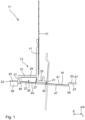
- a plaster sealing strip 11 according to the invention is shown in various views.
- the structural design of the plaster sealing strip 11 can probably best be understood from the cross-sectional view in Fig.1 recognize.
- the plaster sealing strip 11 comprises a profile body 13 which extends in a longitudinal direction L which is perpendicular to the plane of the Fig.1
- the profile body 13 has a base leg 15, a cleaning leg 17 and a pivoting leg 19.
- the base leg 15 extends from a front end, which functions as a plaster removal edge 21, to a rear end 23.
- the base leg 15 is aligned along an insertion direction E, which is orthogonal to the longitudinal direction L and in Fig.1 runs horizontally.
- the base leg 15 is formed by several sections, each of which has a straight course. Starting from the plaster removal edge 21, the base leg 15 initially has a Plaster delimitation section 25, to which a front wall section 27, a base section 29, a rear wall section 31 and finally a fastening section 33 are connected, wherein the fastening section 33 comprises the said rear end 23 of the base leg 15.
- the base section 29 is aligned parallel to the insertion direction E, while the front wall section 27 and the rear wall section 31 are aligned perpendicular thereto.
- the front wall section 27, the base section 29 and the rear wall section 31 delimit a receptacle 35 into which a sealing tape 37, in particular a pre-compressed joint sealing tape, is or can be inserted.
- the fastening section 33 protrudes orthogonally from the rear wall section 31 and is thus aligned parallel to the insertion direction E and offset from the base section 29.
- an adhesive in the form of a foam adhesive tape 39 is provided for at least temporarily fixing the plaster sealing strip 11 during assembly.
- the plaster leg 17 is aligned perpendicular to the insertion direction E and is connected to the base leg 15 at the transition between the front wall section 27 and the base section 29. As a result, the plaster leg 17 protrudes from the base leg 15 in a normal direction N perpendicular to the insertion direction E and is arranged as an extension of the front wall section 27.
- the normal direction N is orthogonal to the longitudinal direction L and runs in Fig.1 vertically.
- the plaster leg 17 has an at least substantially continuous straight course along the normal direction N.
- a reinforcing fabric 41 is attached to the plaster leg 17 and extends in the normal direction N beyond the plaster leg 17.
- the pivoting arm 19 is hinged to the base arm 15 so that it can be moved between the Fig.1 shown in solid line and the mounting position in Fig.1 can be swiveled by 90° into the deflection position also shown, but indicated by a dotted line.
- the pivoting leg 19 is attached to the base leg 15 via a soft connection 43, which is arranged on an underside (i.e. on a side facing away from the plastering leg 17) of the plastering delimitation section 25 in the area of the plastering edge 21. While the pivoting leg 19 is made of the same rigid material as the base leg 15 and the plastering leg 17, the soft connection 43 is made of a (significantly) softer material in comparison, namely soft PVC. This can advantageously be co-extruded together with the material of the base leg 15 and the plastering leg 17, so that only a single extrusion step needs to be provided to produce the entire profile body 13.
- the position at which the soft connection 43 is arranged on the pivot leg 19 corresponds to a transition between a holding section 45 and a cover section 47 of the pivot leg 19, which merge seamlessly into one another along this transition and have a continuous straight course overall.
- the holding section 45 extends from the aforementioned transition initially along the plaster limiting section 25 of the base leg 15 to the front wall section 27 and from there to the rear wall section 31.
- the swivel leg 19 is aligned approximately parallel to the normal direction N in the deflection position and approximately parallel to the insertion direction E in the assembly position, but in each case shows a clear deviation from an exactly parallel alignment.
- the Holding section 45 and the cover section 47 of the pivoting leg 19 are thereby aligned obliquely in the assembly position relative to the insertion direction E, namely at an angle of approximately 4° to 5° to the insertion direction E.
- the plaster limiting section 25 has a comparably oblique alignment relative to the insertion direction E.
- the inclination of the holding section 45 results in the sealing strip 37, which in the expanded state has an at least substantially rectangular cross-section, being compressed more and more with increasing distance from the front wall section 27, so that it presses most strongly against the holding section 45 at the rear wall section 31.
- the holding section 45 and thus the entire pivoting leg 19 is held in its assembly position by a projection 49 against the force exerted by the sealing strip 37.
- the projection 49 is designed as a locking lug with a run-on slope and is arranged in such a way that when the pivoting leg 19 is pivoted into the assembly position, the free end of the holding section 45 runs against the run-on slope and thereby pushes the projection 49 back so that the holding section 45 can pass the projection 49 and the projection 49 then engages behind the holding section 45.
- the pivoting leg 19 is held particularly reliably in its assembly position and the sealing strip 37 is held particularly reliably in its compressed state.
- the cover section 47 extends far beyond the base leg 15 in the opposite direction to the insertion direction E. This allows its plaster leg side Surface for attaching a protective film to protect the respective component during plastering.
- an adhesive 51 in the form of an adhesive strip is attached to this surface.
- the pivoting leg 19 also has a gripping section 53 which is connected to the covering section 47 at the end of the covering section 47 opposite the holding section 45 via a bend 55.
- the gripping section 53 is offset in the normal direction N relative to the covering section 47.
- the gripping section 53 has a corrugation 57 in the form of ribs which are provided both on the cleaning leg side and on the opposite surface of the gripping section 53 and which run parallel to the longitudinal direction L.
- This design allows the gripping section 53 to be gripped relatively easily and reliably in order to pull the entire pivot leg 19 in the direction opposite to the insertion direction E and thereby separate the soft connection 43 so that the pivot leg 19 can be completely removed from the rest of the profile body 13. In this way, after assembly and plastering, the pre-compressed sealing tape 37 can be released for expansion. This is also made possible by the Fig. 2 and 3 illustrated.
- Fig. 2 is a state after the installation of the plaster sealing strip 11 in the area of a joint between a building element 59 and a building wall 61, but before the plaster sealing strip 11 is plastered onto the building wall 61.
- the plaster sealing strip 11 in this state is inserted into the joint with a part of the base leg 15, namely essentially with the base section 29, the rear wall section 31 and the fastening section 33, in the insertion direction E, so that the base section 29 and the plaster leg 17 rest on the two sides of a corner of the building wall 61.
- the plaster sealing strip 11 is already provisionally fixed in position, namely on the one hand by the foam adhesive tape 39 on the fastening section 33 of the base leg 15, which rests on the structural element 59 and is possibly glued thereto, and on the other hand by the end of the cover section 47 opposite the holding section 45, which also rests on the structural element 59 due to the inclination of the cover section 47, so that overall a reliable support of the plaster sealing strip 11 is obtained.
- the plaster sealing strip 11 After the plaster sealing strip 11 has been temporarily fixed in position in this way, it can be plastered in.
- a base coat 63 is applied first and then a top coat 65 is applied (cf. Fig.3 ), whereby the front end of the plaster limiting section 25 of the base leg 15 of the plaster sealing strip 11 can be used as a plaster removal edge 21 for applying the finishing plaster 65.
- the structural element 59 in particular the pane of a window or a French window, can be protected from dirt by a protective film attached to the cover section 47 of the pivoting leg 19 by means of the adhesive 51.
- the cover section 47 is no longer required; in addition, the sealing tape 37 should be able to expand in order to reliably seal the joint between the building element 59 and the building wall 61 and also to allow a certain amount of movement compensation (whereas the foam adhesive tape 39 can tear or come off if the joint expands).
- Both goals are achieved by the pivoting leg 19 being released from the rest of the profile body 13 by pulling on the gripping section 53 in the direction opposite to the insertion direction E. Due to the arrangement of the soft connection 43 below (on the side facing away from the plaster leg 17) the base leg 15, pulling in the direction opposite to the insertion direction E leads to Direction causes the soft connection 43 to be sheared and thereby separated. As soon as the holding section 45 of the pivoting leg 19 no longer limits the receptacle 35 in the direction opposite to the normal direction N, the sealing band 37 can expand until it rests against the component 59.
Landscapes
- Engineering & Computer Science (AREA)
- Civil Engineering (AREA)
- Structural Engineering (AREA)
- Architecture (AREA)
- Building Environments (AREA)
Applications Claiming Priority (1)
| Application Number | Priority Date | Filing Date | Title |
|---|---|---|---|
| DE102023105542.9A DE102023105542A1 (de) | 2023-03-07 | 2023-03-07 | Anputzdichtleiste |
Publications (1)
| Publication Number | Publication Date |
|---|---|
| EP4428320A1 true EP4428320A1 (fr) | 2024-09-11 |
Family
ID=90362435
Family Applications (1)
| Application Number | Title | Priority Date | Filing Date |
|---|---|---|---|
| EP24161626.7A Pending EP4428320A1 (fr) | 2023-03-07 | 2024-03-06 | Baguette d'étanchéité en plâtre |
Country Status (2)
| Country | Link |
|---|---|
| EP (1) | EP4428320A1 (fr) |
| DE (1) | DE102023105542A1 (fr) |
Citations (5)
| Publication number | Priority date | Publication date | Assignee | Title |
|---|---|---|---|---|
| EP1793061A2 (fr) * | 2005-12-02 | 2007-06-06 | August Braun | Baguette de bord pour une couche d'enduit sur un élément d'isolation thermique |
| DE202017007004U1 (de) * | 2016-08-08 | 2019-02-25 | Christian Mick | Anschlussprofilleiste |
| EP3540144B1 (fr) * | 2018-03-12 | 2020-10-28 | Braun, August | Bande pour crépi destinée à être agencée sur une transition de bâtiment ainsi que transition de bâtiment associée |
| DE102021102672A1 (de) * | 2021-02-04 | 2022-08-04 | Ejot Baubefestigungen Gmbh | Anputzleiste |
| EP3699371B1 (fr) * | 2019-02-19 | 2022-09-14 | K-Uni Kunststoffproduktions- und Handels-GmbH | Profilé de raccordement pour composants adjacents au crépi |
-
2023
- 2023-03-07 DE DE102023105542.9A patent/DE102023105542A1/de active Pending
-
2024
- 2024-03-06 EP EP24161626.7A patent/EP4428320A1/fr active Pending
Patent Citations (5)
| Publication number | Priority date | Publication date | Assignee | Title |
|---|---|---|---|---|
| EP1793061A2 (fr) * | 2005-12-02 | 2007-06-06 | August Braun | Baguette de bord pour une couche d'enduit sur un élément d'isolation thermique |
| DE202017007004U1 (de) * | 2016-08-08 | 2019-02-25 | Christian Mick | Anschlussprofilleiste |
| EP3540144B1 (fr) * | 2018-03-12 | 2020-10-28 | Braun, August | Bande pour crépi destinée à être agencée sur une transition de bâtiment ainsi que transition de bâtiment associée |
| EP3699371B1 (fr) * | 2019-02-19 | 2022-09-14 | K-Uni Kunststoffproduktions- und Handels-GmbH | Profilé de raccordement pour composants adjacents au crépi |
| DE102021102672A1 (de) * | 2021-02-04 | 2022-08-04 | Ejot Baubefestigungen Gmbh | Anputzleiste |
Also Published As
| Publication number | Publication date |
|---|---|
| DE102023105542A1 (de) | 2024-09-12 |
Similar Documents
| Publication | Publication Date | Title |
|---|---|---|
| EP2404008B1 (fr) | Dispositif d'étanchéité sur un joint dans une construction | |
| EP0628121B1 (fr) | Bande de crepissage et de protection pour chassis de fenetre, batis de porte ou analogue pour la jonction avec le crepi | |
| DE10023697A1 (de) | Profilleiste zum Abdichten einer Bewegungsfuge zwischen einem Bauteil und einer Putzschicht | |
| EP1793061B1 (fr) | Baguette de bord pour une couche d'enduit sur un élément d'isolation thermique | |
| EP0801189B1 (fr) | Profilé de raccord pour ouvertures de portes et fenêtres | |
| DE20008712U1 (de) | Profilleiste zum Abdichten einer Bewegungsfuge zwischen einem Bauteil und einer Putzschicht | |
| EP2492429B3 (fr) | Bande de crépissage ainsi qu'angles de construction dotés d'une bande de crépissage | |
| EP2853653A2 (fr) | Bande de crépissage, bande et rail de terminaison | |
| EP3805480A1 (fr) | Bande d'étanchéité en plâtre | |
| EP3808918B1 (fr) | Transition de bâtiment avec bande pour crépi | |
| EP1722064B1 (fr) | Profilé de jonction, notamment profilé de jonction de tableau | |
| DE9407166U1 (de) | Anputz- und Schutzleiste für Fensterstöcke, Türstöcke o.dgl. am Übergang zu Putz | |
| DE202009010042U1 (de) | Einteilige Abdicht- oder Anputzleiste | |
| EP2270304B1 (fr) | Profilé d'enfichage et/ou d'introduction | |
| EP3848549B1 (fr) | Baguette de limitation de crépi ainsi que transition de bâtiment pourvu de limitation de crépi | |
| DE102023105542A1 (de) | Anputzdichtleiste | |
| DE10229610A1 (de) | Abschluss | |
| DE29620179U1 (de) | Stoßprofil für Fenstereinbindungen | |
| DE102005012537B3 (de) | Profilleiste zum Anschließen einer Verkleidungsplatte, insbesondere einer Leibungsauskleidungsplatte an ein Bauteil, insbesondere einen Fenster- oder Türstock oder eine Rolloschiene | |
| EP0558000B1 (fr) | Baquette profilée pour application et protection d'enduit à la jonction des cadres dormants de fenêtres, de portes ou semblable avec de l'enduit | |
| AT528000B1 (de) | Anschlussprofil für an putz angrenzende bauteile mit dichtschlaufe | |
| EP4194638B1 (fr) | Baguette d'étanchéité en plâtre | |
| EP4339393B1 (fr) | Baguette de crépissage et jonction de bâtiment | |
| EP4541996A1 (fr) | Baguette de crépissage | |
| EP3822446B1 (fr) | Élément de profil |
Legal Events
| Date | Code | Title | Description |
|---|---|---|---|
| PUAI | Public reference made under article 153(3) epc to a published international application that has entered the european phase |
Free format text: ORIGINAL CODE: 0009012 |
|
| STAA | Information on the status of an ep patent application or granted ep patent |
Free format text: STATUS: THE APPLICATION HAS BEEN PUBLISHED |
|
| AK | Designated contracting states |
Kind code of ref document: A1 Designated state(s): AL AT BE BG CH CY CZ DE DK EE ES FI FR GB GR HR HU IE IS IT LI LT LU LV MC ME MK MT NL NO PL PT RO RS SE SI SK SM TR |
|
| P01 | Opt-out of the competence of the unified patent court (upc) registered |
Free format text: CASE NUMBER: APP_51833/2024 Effective date: 20240916 |
|
| STAA | Information on the status of an ep patent application or granted ep patent |
Free format text: STATUS: REQUEST FOR EXAMINATION WAS MADE |
|
| 17P | Request for examination filed |
Effective date: 20250221 |