EP4541996A1 - Baguette de crépissage - Google Patents
Baguette de crépissage Download PDFInfo
- Publication number
- EP4541996A1 EP4541996A1 EP23204091.5A EP23204091A EP4541996A1 EP 4541996 A1 EP4541996 A1 EP 4541996A1 EP 23204091 A EP23204091 A EP 23204091A EP 4541996 A1 EP4541996 A1 EP 4541996A1
- Authority
- EP
- European Patent Office
- Prior art keywords
- strip
- plastering
- flexible protective
- region
- protective lip
- Prior art date
- Legal status (The legal status is an assumption and is not a legal conclusion. Google has not performed a legal analysis and makes no representation as to the accuracy of the status listed.)
- Pending
Links
Images


Classifications
-
- E—FIXED CONSTRUCTIONS
- E06—DOORS, WINDOWS, SHUTTERS, OR ROLLER BLINDS IN GENERAL; LADDERS
- E06B—FIXED OR MOVABLE CLOSURES FOR OPENINGS IN BUILDINGS, VEHICLES, FENCES OR LIKE ENCLOSURES IN GENERAL, e.g. DOORS, WINDOWS, BLINDS, GATES
- E06B1/00—Border constructions of openings in walls, floors, or ceilings; Frames to be rigidly mounted in such openings
- E06B1/62—Tightening or covering joints between the border of openings and the frame or between contiguous frames
-
- E—FIXED CONSTRUCTIONS
- E04—BUILDING
- E04F—FINISHING WORK ON BUILDINGS, e.g. STAIRS, FLOORS
- E04F13/00—Coverings or linings, e.g. for walls or ceilings
- E04F13/02—Coverings or linings, e.g. for walls or ceilings of plastic materials hardening after applying, e.g. plaster
- E04F13/04—Bases for plaster
- E04F13/06—Edge-protecting borders
- E04F13/068—Edge-protecting borders combined with mesh material or the like to allow plaster to bond therewith
-
- E—FIXED CONSTRUCTIONS
- E04—BUILDING
- E04F—FINISHING WORK ON BUILDINGS, e.g. STAIRS, FLOORS
- E04F13/00—Coverings or linings, e.g. for walls or ceilings
- E04F13/02—Coverings or linings, e.g. for walls or ceilings of plastic materials hardening after applying, e.g. plaster
- E04F13/04—Bases for plaster
- E04F13/06—Edge-protecting borders
- E04F2013/063—Edge-protecting borders for corners
-
- E—FIXED CONSTRUCTIONS
- E06—DOORS, WINDOWS, SHUTTERS, OR ROLLER BLINDS IN GENERAL; LADDERS
- E06B—FIXED OR MOVABLE CLOSURES FOR OPENINGS IN BUILDINGS, VEHICLES, FENCES OR LIKE ENCLOSURES IN GENERAL, e.g. DOORS, WINDOWS, BLINDS, GATES
- E06B1/00—Border constructions of openings in walls, floors, or ceilings; Frames to be rigidly mounted in such openings
- E06B1/62—Tightening or covering joints between the border of openings and the frame or between contiguous frames
- E06B2001/622—Tightening or covering joints between the border of openings and the frame or between contiguous frames especially adapted for door frames; Joint covering devices where the wall surface is parallel to the adjacent door or window frame part
-
- E—FIXED CONSTRUCTIONS
- E06—DOORS, WINDOWS, SHUTTERS, OR ROLLER BLINDS IN GENERAL; LADDERS
- E06B—FIXED OR MOVABLE CLOSURES FOR OPENINGS IN BUILDINGS, VEHICLES, FENCES OR LIKE ENCLOSURES IN GENERAL, e.g. DOORS, WINDOWS, BLINDS, GATES
- E06B1/00—Border constructions of openings in walls, floors, or ceilings; Frames to be rigidly mounted in such openings
- E06B1/62—Tightening or covering joints between the border of openings and the frame or between contiguous frames
- E06B2001/624—Tightening or covering joints between the border of openings and the frame or between contiguous frames with parts to be embedded in the stucco layer or otherwise linked to this layer
Definitions
- the present invention relates to a plastering strip for arrangement at a building transition, a building transition with such a plastering strip, a method for attaching a plastering strip to a building transition and a method for producing a plastering strip.
- Plastering beads come in a variety of designs. They are particularly commonly used where a layer of plaster on the exterior surface of a building wall or the reveal of a window or door opening in a building ends, e.g., where thermal insulation applied to the exterior surface or reveal surface ends in the area of a window or door frame.
- conventional adhesive or sealing strips are used to attach plastering strips to a window or door frame and to seal the building transition.
- a plastering strip according to the invention for arrangement at a building transition between a first building component, in particular a window or door frame, a window sill, a pilaster strip, a beam or a base, and a second building component, in particular a thermal insulation and/or a plaster layer on a thermal insulation or on a building wall, comprises the features of independent patent claim 1.
- the flexible protective lip extends from the plastering bead, to which it is attached with its rear end and with which it is integrally connected, for example by extrusion, in particular coextrusion, to the first building component to which it rests with its tip.
- the flexible protective lip fulfils several functions, namely the function of a protective and sealing lip by protecting and sealing the building transition from rain, driving rain, incoming moisture, wind and fire, and by protecting the areas behind the building transition, the plastering strip and in particular protects the expansion strip against UV radiation and thus against rapid aging and damage.
- the flexible protective lip serves to visually conceal the area of the building transition and the plastering strip located behind it, in particular to visually conceal the expansion strip located behind it.
- the flexible protective lip is positioned, in particular with its rear end, on the back of the plastering strip and is, in particular, integrally connected to it.
- the flexible protective lip can be arranged on the back of the base area of the plastering strip.
- the plastering strip in addition to the flexible protective lip, has an expansion strip which ensures a compressive seal against the first building component and also reliably seals the building transition.
- the plastering strip according to the invention can be attached to the desired position at the building transition in the delivery state, then the plastering work can be carried out and completed, and finally the confined area, in particular the removable material strip, can be removed safely and easily.
- This allows the expansion strip to expand and adhere to the first building component, and also allows the flexible Move the protective lip to its second position, the resting position on the first building component.
- the expansion strip may be a delayed expansion strip which, after removal of the containment area, in particular the removable material strip, expands backwards and rests against the first building component.
- the presence of the flexible protective lip at a position inward from the inside of the expansion strip allows the use of a lower-quality expansion strip, while still meeting the technical requirements for a high-quality seal for the building transition.
- a lower-quality expansion strip may, for example, have a lower density and be unimpregnated or less impregnated.
- expansion strip can be of high quality.
- the additional protection provided by the flexible protective lip meets particularly stringent waterproofing requirements, particularly with regard to driving rain resistance, especially in coastal regions or high-rise construction.
- the UV protection provided by the flexible protective lip compared to the expansion strip results in a high level of durability and resistance of the plastering strip and thus in a permanently and reliably sealed building transition.
- the plastering area of the plastering strip can be located at the front of the base area.
- the plastering area can be formed in particular by the inside of a plastering leg and by the top side of the area of the plastering strip located inside the plastering leg.
- the end region of the flexible protective lip in the first position of the flexible protective lip, is arranged between the containment region and the expansion strip and extends substantially outwards and/or substantially parallel to the main extension direction of the expansion strip or a base wall of the base region.
- the end region of the flexible protective lip in the first position of the flexible protective lip, is arranged on a contact section or on a receiving section of the locking section and extends substantially inwards and/or substantially parallel to the main extension direction of the expansion strip or a base wall of the base section.
- the flexible protective lip moves from the first to the second position, extending the end region backwards, without reversing its direction, to rest against the first building component.
- the flexible protective lip In the receiving area of this flexible material strip, the flexible protective lip is thus securely held in its holding position, but is compressed by it from bottom to top or from back to front.
- the flexible protective lip particularly its previously compressed end area, expands backward, and the flexible protective lip assumes its second position, the holding position, in which it rests against the first building component.
- the flexible protective lip does not reverse its direction during this process.
- the flexible protective lip in particular its tip, can in particular be unconnected to the containment area, in particular the removable material strip.
- the end region of the flexible protective lip in the first position of the flexible protective lip, is arranged in a receiving region of the locking region and extends substantially outwards and/or substantially parallel to the main extension direction of the expansion strip or a base wall of the base region.
- the receiving area of the locking area can be designed as a pocket, with an outward extension direction and/or substantially parallel to the main extension direction of the expansion strip or a base wall of the base area, with an insertion opening which, in the delivery state of the plastering strip, in which the locking area is fixed to the plastering strip, is arranged at a width position which approximately corresponds to the position of the inside of the expansion strip.
- the flexible protective lip moves from the first to the second position, performing a reversal of direction, in which it extends with its end region backwards and inwards, as seen from its rear end, to bear against the first building component.
- the end region of the flexible protective lip can first slide out of the receiving area of the locking area in an inward direction, reversing the direction from outwards to inwards, and can then move backwards into the second position, extending the end region.
- the guiding of the flexible protective lip from its first holding position to its second functional position can be assisted by the flexible protective lip being lightly connected to the containment area/removable material strip at an area of its tip.
- the flexible protective lip in the delivery state of the plastering strip, is detachably connected, in particular lightly connected, to the locking area by its tip.
- the flexible protective lip can initially move into the second position when the containment area is removed. This detachable connection, particularly the light connection between the flexible protective lip and the containment area, is then severed.
- Such a separable connection in particular easy connection of the flexible protective lip with its tip opposite the locking area, ensures reliable guidance of the flexible protective lip into the second functional position, in particular in the embodiments in which a reversal of direction of the flexible protective lip between its first holding position and its second functional position is required.
- the flexible protective lip is attached with its rear end to a portion of the base region, to an attachment position between the inner side of the expansion strip and the inner end of the base region, in particular to a step formed therebetween.
- the flexible protective lip is particularly well positioned and can fulfill its tasks very well.
- the flexible protective lip is designed in such a way that, after removing the containment area, it covers a joint up to the first building component.
- the plastering strip has an outer wall on the outside of the expansion strip, which delimits a receiving space for the expansion strip on the outside.
- the removable material strip can, in particular, in the delivery state of the plastering strip, be locked with a locking projection which is provided in particular on the inside of the outer wall.
- the removable material strip rests against the underside of the base region, in particular against the inner end of the underside of the base region, or is connected thereto or locked thereto.
- the removable material strip is connected to the underside of the base region, in particular to the inner end of the underside of the base region, via a break-off material bridge or via a connecting bridge.
- the flexible protective lip has, in particular, a slight curvature, seen from front to back, i.e. in the direction of the first building component, inwards.
- the plastering strip in the delivery state has a strip-shaped protective tab for fastening a cover film to the front thereof, which is connected in particular via a break-off material bridge or via a connecting bridge to the underside of the base area, in particular to the inner end of the underside of the base area, and/or which in particular has a rear spacer web.
- the break-off material bridge or connecting bridge is designed as a double break-off material bridge or connecting bridge, which connects the plastering strip and the removable material strip with the strip-shaped protective tab.
- a double breakaway material bridge or double connecting bridge allows the strip-shaped protective tab and the removable material strip to be detached independently from the plastering strip.
- the strip-shaped protective flap along with the protective film applied to it, can be removed and disposed of in a first step.
- the removable material strip can then be pulled inward, thereby releasing the expansion strip for expansion and moving the flexible protective lip into its second functional position.
- the removable material strip has a stepped profile.
- a first step can be arranged at the inner end of the expansion strip.
- the removable material strip may have a gripping portion extending inward beyond the base area, by means of which the removable material strip can be removed from the remaining body of the plastering strip.
- the gripping portion When delivered, the gripping portion may be concealed by the strip-shaped protective tab when viewed from the front.
- the stepped course of the removable material strip ensures reliable locking of the strip against the base body of the plastering strip and reliable retention of the flexible protective lip in its holding position.
- the gripping section allows the removable material strip to be reliably gripped and removed from the base body of the plastering strip.
- the invention also relates to a building transition having the features of claim 13.
- Such a building transition is reliably and permanently sealed by both the flexible protective lip and the expansion strip.
- the flexible protective lip protects the expansion strip from the outside and conceals it from view.
- the invention also relates to a method for attaching a plastering strip to a building transition with all the features and method steps of claim 14.
- the process is therefore easy to carry out and results in a particularly reliable and permanently sealed building transition.
- the present invention also relates to a method for producing a plastering strip having the features of claim 15.
- a plastering strip of the type described here can be produced reliably and cost-effectively.
- Figure 1 shows a side view of a plastering strip 2 according to a first embodiment of the present invention in the delivery state.
- the plastering strip 2 is intended for arrangement at a building transition between a first building component, which can be designed as a window or door frame, as a window sill, as a pilaster strip, as a beam, as a base, as a roller shutter guide rail, or as a slat guide rail, and a second building component, which can be designed as thermal insulation and/or as a plaster layer on a building wall.
- a first building component which can be designed as a window or door frame, as a window sill, as a pilaster strip, as a beam, as a base, as a roller shutter guide rail, or as a slat guide rail
- a second building component which can be designed as thermal insulation and/or as a plaster layer on a building wall.
- a typical installation situation of the plastering strip 2 is in the Figure 3(c) shown In the Figures 1 to 4
- the terms front and back are understood as being above and below in the drawing plane.
- the terms inside/left and outside/right are understood as being on the left and right in the drawing plane.
- the plastering strip 2 has a base area 4 with an expansion strip 20 attached thereto, a fixing leg 8, a plastering leg 10 with a reinforcement mesh section 12 attached thereto, a plastering area 16, a strip-shaped protective flap 28 and a locking area with a removable material strip 38.
- the base region 4 comprises a base wall 6 extending from left to right and a right outer wall 34 in which a step is formed and at the lower end of which a leftward, i.e., inwardly directed locking projection 26 is arranged for the removable material strip 38.
- a pivotable and/or removable fixing leg 8 is attached via a material bridge of reduced material thickness 18/via a groove 18, which is integrally connected to the outer wall 34.
- a plastering leg 10 is provided, which projects forward at a right angle away from the base wall 6.
- the inner side of the plastering leg 10 and the upper side of the section of the base wall 6 located inside the plastering leg 10 form the plastering area 16.
- a grooved surface profile is provided, which enlarges the surface against which a plaster layer to be applied rests and thus improves the adhesion of the plaster.
- a reinforcing mesh section 12 which may be formed as a net-like glass silk fabric, is attached to the plaster leg 10.
- the reinforcing mesh section 12 is attached to the inside of the plaster leg 10 by means of ultrasonic welding.
- a connector projection 24 is arranged a short distance inward from the plastering leg 10 and projects forward from the base wall 6.
- a receiving space for a connector is formed between the connector projection 24 and the plastering leg 10, particularly its transition area.
- An expansion strip 20 with delayed expansion is provided on the back of the base wall 6 and is in particular attached, e.g. glued, to the underside of the base wall 6.
- the expansion strip 20 is received in a channel-like receiving area which is bounded on the left by the stepped inner end of the plastering bead 2 and on the right by the outer wall 34 which starts at the outer right end of the base wall 6 and extends rearwardly therefrom at right angles.
- the upper side of the section of the base wall 6 located to the right of the plastering leg 10 and the right outer side of the plastering leg 10 form a receiving area for thermal insulation or for a base plaster layer.
- the fixing leg 8 is connected to the lower end of the outer wall 34 of the base region 4 by means of a so-called film hinge, i.e. by means of a connecting bridge made of the same material as the base region 4 and the fixing leg 8, but of reduced material thickness.
- the fixing leg 8 and thus the entire plastering strip 2 can be fixed to the first building component, in particular to the front side, as shown in the Figure 3 shown, or attached to its outside (not shown) or to the thermal insulation (not shown).
- this locking region comprises a removable material strip 38 having its right outer locking end 40 locked above the locking projection 26.
- the removable material strip 38 has in the embodiment of the Figure 1 a tiered structure.
- the removable material strip 38 comprises, viewed from right to left, a locking end 40 which runs parallel to the base wall 6 and by means of which the removable material strip 38 is locked to the locking projection 26, a first step 42 which, in the delivered state of the plastering bead 2, is arranged at a width position approximately one third of the width of the expansion strip 20, a receiving section 44 which also runs parallel to the base wall 6 but is set back relative to the locking end 40, for the flexible protective lip 36, which will be explained in more detail later, a second step 46 on which a soft material bridge 30 is attached to the plaster removal edge of the main body of the plastering bead 2 and to the strip-shaped protective tab 28, and a gripping section 48 which also runs approximately parallel to the base wall 6 but is set back further to the rear and is provided with a roughened portion on its left inner end for better gripping.
- the strip-shaped protective flap 28 extends inwards from the left inner end of the base wall 6 and is connected to the end of the plaster removal edge via a material bridge 30, which can be designed either as a soft material bridge or as a break-off material bridge.
- the strip-shaped protective flap 28 has a spacer 32, which initially rests against the front of the first building component when the plastering strip 2 is installed at a building transition.
- An adhesive strip can be arranged on the front of the strip-shaped protective flap, to which a protective film can be attached. This film spans the first building component and thus protects it from damage and dirt during the installation and plastering process.
- the gripping section 40 of the locking area 34 is covered by the strip-shaped protective tab 28 when viewed from the front.
- both parts can also be provided in one. This can be particularly well imagined if one looks at Figure 1 the gripping section 48 is omitted and the material bridge is imagined as a connection from the strip-shaped protective flap 28 to the base wall 6 and to the removable material strip 38.
- the removable material strip 38 is firmly connected to the plastering strip 2. This holds the expansion strip 20 in the compressed state, and also holds the flexible protective lip 36 in the receiving space formed between the receiving portion 44 of the removable material strip 38 and the underside of the expansion strip 20 inside the first step 42 of the removable material strip 38.
- the flexible protective lip 36 is in its holding position. It extends downward and outward, i.e., to the right, from its upper end, which rests on a step between the base wall 6 and the inner plastering edge end of the plastering bead 2. Its lower end region, located near its tip, thus runs parallel to the base wall 6, and its tip rests on the step 42 of the removable material strip 38 or is slightly spaced therefrom.
- the flexible protective lip 36 is made in particular from a plastic material that is softer than the hard plastic material of the base body of the plastering strip 2, in particular by means of co- or tri-extrusion.
- the plastering strip 2 is now attached and fastened as follows to a building transition between a first building component and a second building component, in particular a thermal insulation and/or a plaster layer on a thermal insulation or on a building wall.
- the first building component will be referred to as a window frame and the second building component as thermal insulation.
- the plastering strip 2 is attached to the outside of the window frame (54, in Fig. 3 ), especially glued.
- the plastering strip 2 is placed in the Figure 1 In the delivery condition shown, it is either inserted into a gap between the thermal insulation and the window frame, or the plastering strip 2 is first attached to the window frame and then the thermal insulation is inserted.
- the thermal insulation is applied to the outside of the plaster leg 10 and to the top of the base wall 6 outside the plaster leg 10.
- a film is attached to the strip-shaped protective flap 28 and stretched over the window. Subsequently, one or more layers of plaster are applied, penetrating the reinforcing mesh 12, as is known to those skilled in the art.
- the strip-shaped protective flap 28 and the removable material strip 38 are removed by cutting through the soft material bridge 30.
- Figure 1 in the drawing plane to the left, i.e. pulled out inwards, which can be supported by a pivoting movement. This puts the expansion strip 20 into the state released for expansion, so that it can be pulled backwards, inwards Figure 1 can extend downwards in the drawing plane and attach itself to the outer surface of the window frame.
- the flexible protective lip 36 is Figure 1 shown holding position into its functional position, in which it extends backwards and inwards from its upper attachment end on the step between the base wall 6 and the inner plaster removal edge and thus also rests against the window frame.
- Moving the flexible protective lip 36 from its holding position into Figure 1 to their functional position in Figure 3(c) can be supported by the flexible protective lip 36 being releasably connected, in particular lightly connected, with its tip, for example to a region of the first step 42 of the removable material strip 38, for example by a co- or tri-extruded predetermined tear point region.
- the flexible protective lip 36 When pulling out the removable material strip 38 in Figure 1 To the left, the flexible protective lip 36 is first raised and brought into its functional position, in which it extends rearward and inward, reversing its direction. Upon further pulling the removable material strip 38 inward, this separable connection/light connection of the flexible protective lip 36 to the removable material strip 38 tears, and the flexible protective lip 36 securely adheres to the outer surface of the window frame.
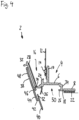
- the Figure 2 The plastering strip 2 shown corresponds in terms of its structure, components and features to the plastering strip 2 from Figure 1 .
- the plastering strip 2 from Figure 2 differs from the plastering strip 2 Figure 1 with regard to the arrangement of the first stage 42, with regard to the formation of the receiving area 44 of the removable material strip 38 and with regard to the holding position of the flexible protective lip 36.
- the removable material strip 38 in turn comprises an outer locking end 40, which, in the delivery state of the plastering strip 2, runs parallel to the base wall 6 and whose outer end is locked relative to the locking projection 26, a first step 42, which is arranged at the level of the inner end of the expansion strip 20, a recessed receiving section 44, which extends between the first step 42 and the second step 46, at which the removable material strip 38 is connected by means of a material bridge 30 to the plastering edge end of the base body of the plastering strip 2 and to the removable protective flap 28, and the inner gripping section 48, which corresponds to the gripping section 48 of Figure 1 corresponds.
- the receiving section 44 is thus further inward and further set back downwards than in the plastering strip 2 from Figure 1 .
- the flexible protective lip 36 is arranged and received in its holding position within the receiving area which is formed to the right by the first step 42, to the left by the second step 46 and downwards by the receiving section 44 of the removable material strip 38 and upwards by the stepped transition of the plastering bead 2 between the base wall 6 and the inner plastering edge end.
- the flexible protective lip 36 In the holding position of the flexible protective lip 36, which is in Figure 2 As shown, it extends downwards and inwards from its rear end, with which it attaches to the stepped transition of the plastering bead 2 between the base wall 6 and the inner plastering edge end, with its tip. The end region of the flexible protective lip 36 with the tip is thus compressed upwards by the receiving section 44 of the removable material strip 38.
- the installation/assembly of the plastering strip 2 corresponds to that described above, which will not be explained again to avoid repetition.
- the flexible protective lip 36 also extends downwards with its end region and in particular with its tip, without reversing its direction, and is moved into its second functional position in which its tip rests against the outer surface of the window frame.
- the Figure 3(a) The plastering strip 2 shown corresponds in terms of its structure and components/features to the plastering strip 2 from Figure 1 . Identical elements are identified by the same reference numerals and will not be explained again to avoid repetition.
- the plastering strip 2 from Figure 3 differs from the plastering strip 2 Figure 1 regarding the design of the receiving area of the removable material strip 38 and regarding the holding position of the flexible protective lip 36.
- the flexible protective lip 36 is not located in a receiving area whose upper side is formed by the underside of the expansion strip 20, but in a receiving area which is completely formed by the removable material strip 38.
- the removable material strip 38 has a receiving section which is designed in the form of a horizontal pocket.
- the removable material strip 38 comprises, viewed from right to left, a locking end 40 which runs parallel to the base wall 6 and whose outer end is locked to the locking projection 26, a step 42 approximately at the level of one third of the width of the expansion strip 20, a contact section 44 which is set back downwards relative to the latter, a second step 46 at the level of the left, inner end of the plastering area 16, the second step 46 being connected to the inner end of the plastering area 16 and to the strip-shaped protective tab 28 by means of a material bridge 30, and via the gripping section 48 which corresponds to the gripping section 48 explained in detail above.
- the removable material strip 38 to the left of the first step 42, in extension of the locking end 40, has an upper end leg / pocket limiting leg 52 of slightly smaller thickness than the locking end 40.
- This upper end leg 52 extends, in the delivery state of the plastering strip 2, in Figure 3(a) shown, to the left inner end of the expansion strip 20.
- the flexible protective lip 36 is arranged with its upper, rear end on the step between the base wall 6 and the removal edge end of the base body of the plastering strip 2 and is in particular co- or tri-extruded with the base body of the plastering strip 2.
- the flexible protective lip 36 extends from there downwards and to the right into the receiving area of the flexible material strip 38 and rests with its underside on the lower receiving section 44; its tip can in particular rest on the pocket end or the first step 42 or be arranged at a slight distance therefrom.
- the installation/assembly of the plastering strip 2 corresponds to that described above, which will not be explained again to avoid repetition.
- the flexible protective lip 36 is thereby Figure 3(a) shown holding position into its Figure 3(c) shown functional position by first sliding inwards out of the receiving area/pocket of the locking area 38 and reversing the direction from outwards to inwards, as shown in Figure 3(b) is shown.
- the flexible protective lip 36 being separably connected, in particular lightly connected, to the removable material strip 38 at its tip or at a region near its tip by a material section, in particular in the region of the receiving area/pocket.
- the strip-shaped protective tab 38 and the removable material strip 38 on the material bridge 30 are pivoted clockwise towards the inner end of the plastering area, in particular towards the inner plaster removal edge.
- the reinforcement mesh section 12 is attached to the plaster leg 10, e.g., by means of ultrasonic welding 14. Access to the receiving area 50 is thus free from below.
- the expansion strip 20 is inserted from below into the receiving space 50, which is formed to the right by the outer wall 34 and to the left by the stepped transition from the base wall 6 to the plaster removal edge, and is fastened, typically by gluing, to the underside of the base wall 6.
- the removable material strip 38 together with the strip-shaped protective flap 28 is now inserted counterclockwise into the Figure 3(a) shown delivery position, inserting the flexible protective lip 36 into the receiving area/pocket between the upper end leg 52 and the receiving section 44, and locking the locking end 40 relative to the locking projection 26.
Landscapes
- Engineering & Computer Science (AREA)
- Architecture (AREA)
- Civil Engineering (AREA)
- Structural Engineering (AREA)
- Building Environments (AREA)
Priority Applications (1)
| Application Number | Priority Date | Filing Date | Title |
|---|---|---|---|
| EP23204091.5A EP4541996A1 (fr) | 2023-10-17 | 2023-10-17 | Baguette de crépissage |
Applications Claiming Priority (1)
| Application Number | Priority Date | Filing Date | Title |
|---|---|---|---|
| EP23204091.5A EP4541996A1 (fr) | 2023-10-17 | 2023-10-17 | Baguette de crépissage |
Publications (1)
| Publication Number | Publication Date |
|---|---|
| EP4541996A1 true EP4541996A1 (fr) | 2025-04-23 |
Family
ID=88417071
Family Applications (1)
| Application Number | Title | Priority Date | Filing Date |
|---|---|---|---|
| EP23204091.5A Pending EP4541996A1 (fr) | 2023-10-17 | 2023-10-17 | Baguette de crépissage |
Country Status (1)
| Country | Link |
|---|---|
| EP (1) | EP4541996A1 (fr) |
Citations (3)
| Publication number | Priority date | Publication date | Assignee | Title |
|---|---|---|---|---|
| EP1793061A2 (fr) * | 2005-12-02 | 2007-06-06 | August Braun | Baguette de bord pour une couche d'enduit sur un élément d'isolation thermique |
| DE202009010042U1 (de) * | 2009-07-23 | 2009-10-01 | Braun, August | Einteilige Abdicht- oder Anputzleiste |
| EP1783061B1 (fr) | 2004-07-30 | 2013-05-15 | Yushin Co., Ltd. | Buse émettant un jet de liquide avec un sac d'emballage |
-
2023
- 2023-10-17 EP EP23204091.5A patent/EP4541996A1/fr active Pending
Patent Citations (3)
| Publication number | Priority date | Publication date | Assignee | Title |
|---|---|---|---|---|
| EP1783061B1 (fr) | 2004-07-30 | 2013-05-15 | Yushin Co., Ltd. | Buse émettant un jet de liquide avec un sac d'emballage |
| EP1793061A2 (fr) * | 2005-12-02 | 2007-06-06 | August Braun | Baguette de bord pour une couche d'enduit sur un élément d'isolation thermique |
| DE202009010042U1 (de) * | 2009-07-23 | 2009-10-01 | Braun, August | Einteilige Abdicht- oder Anputzleiste |
Similar Documents
| Publication | Publication Date | Title |
|---|---|---|
| EP2404009B1 (fr) | Bande de raccordement de profilé avec dispositif d'étanchéité pour l'étanchéité des joints | |
| EP4036346B1 (fr) | Profilé de raccordement pour composants adjacents au crépi | |
| EP2492428B3 (fr) | Bande de crépissage ainsi qu'angles de construction dotés d'une bande de crépissage | |
| EP2281971B1 (fr) | Baguette de bord pour une couche d'enduit sur un élément d'isolation thermique | |
| EP3569791B1 (fr) | Baguette de limitation de crépi, utilisation d'une bande adhésive en mousse double face dans une baguette de limitation de crépi destinée à être placée sur une transition de bâtiment ainsi que transition de bâtiment doté d'une telle baguette de limitation de crépi | |
| DE20008712U1 (de) | Profilleiste zum Abdichten einer Bewegungsfuge zwischen einem Bauteil und einer Putzschicht | |
| EP2492429B3 (fr) | Bande de crépissage ainsi qu'angles de construction dotés d'une bande de crépissage | |
| EP2292886B1 (fr) | Bande d'étanchéité ou de crépissage en une partie | |
| DE202013011085U1 (de) | Anputzleiste, Leiste und Abschlussschiene | |
| EP3808918B1 (fr) | Transition de bâtiment avec bande pour crépi | |
| EP4541996A1 (fr) | Baguette de crépissage | |
| DE202009010042U1 (de) | Einteilige Abdicht- oder Anputzleiste | |
| EP1674649B1 (fr) | Profilé de raccord à deux pièces pour éléments de construction voisins d'un crépi | |
| EP3848549B1 (fr) | Baguette de limitation de crépi ainsi que transition de bâtiment pourvu de limitation de crépi | |
| AT526612B1 (de) | Anschlussprofil für an putz angrenzende bauteile | |
| EP4339393B1 (fr) | Baguette de crépissage et jonction de bâtiment | |
| DE102013110110A1 (de) | Anputzleiste, Abschlussschiene und Putz-Eckleiste und Verfahren zum Herstellen derselben | |
| EP1707728B1 (fr) | Profilé pour raccorder un panneau d'habillage, notamment un panneau d'habillage de tableau de fenêtre, à un élément de construction, notamment un cadre de porte et de fenêtre ou un rail de volet roulant | |
| AT8398U1 (de) | Zweiteiliges laibungsanschlussprofil | |
| EP3587701B1 (fr) | Agencement de profilé de plâtre pour étanchéifier un joint | |
| EP4428320A1 (fr) | Baguette d'étanchéité en plâtre | |
| EP4446551B1 (fr) | Profilé de raccordement pour composants adjacents sur un enduit | |
| EP3822446B1 (fr) | Élément de profil | |
| EP4194638B1 (fr) | Baguette d'étanchéité en plâtre | |
| EP4571013A1 (fr) | Baguette d'étanchéité en plâtre |
Legal Events
| Date | Code | Title | Description |
|---|---|---|---|
| PUAI | Public reference made under article 153(3) epc to a published international application that has entered the european phase |
Free format text: ORIGINAL CODE: 0009012 |
|
| STAA | Information on the status of an ep patent application or granted ep patent |
Free format text: STATUS: THE APPLICATION HAS BEEN PUBLISHED |
|
| AK | Designated contracting states |
Kind code of ref document: A1 Designated state(s): AL AT BE BG CH CY CZ DE DK EE ES FI FR GB GR HR HU IE IS IT LI LT LU LV MC ME MK MT NL NO PL PT RO RS SE SI SK SM TR |
|
| STAA | Information on the status of an ep patent application or granted ep patent |
Free format text: STATUS: REQUEST FOR EXAMINATION WAS MADE |
|
| 17P | Request for examination filed |
Effective date: 20250523 |
|
| GRAP | Despatch of communication of intention to grant a patent |
Free format text: ORIGINAL CODE: EPIDOSNIGR1 |
|
| STAA | Information on the status of an ep patent application or granted ep patent |
Free format text: STATUS: GRANT OF PATENT IS INTENDED |
|
| RIC1 | Information provided on ipc code assigned before grant |
Ipc: E06B 1/62 20060101AFI20260106BHEP Ipc: E04F 13/06 20060101ALI20260106BHEP |
|
| GRAJ | Information related to disapproval of communication of intention to grant by the applicant or resumption of examination proceedings by the epo deleted |
Free format text: ORIGINAL CODE: EPIDOSDIGR1 |
|
| STAA | Information on the status of an ep patent application or granted ep patent |
Free format text: STATUS: REQUEST FOR EXAMINATION WAS MADE |
|
| INTG | Intention to grant announced |
Effective date: 20260122 |
|
| INTC | Intention to grant announced (deleted) | ||
| GRAP | Despatch of communication of intention to grant a patent |
Free format text: ORIGINAL CODE: EPIDOSNIGR1 |
|
| STAA | Information on the status of an ep patent application or granted ep patent |
Free format text: STATUS: GRANT OF PATENT IS INTENDED |