EP4428331A1 - Mécanisme de fenêtre/porte coulissante et fenêtre/porte coulissante ou battant de porte. châssis de fenêtre/porte coulissante avec mécanisme de fenêtre/porte coulissante - Google Patents
Mécanisme de fenêtre/porte coulissante et fenêtre/porte coulissante ou battant de porte. châssis de fenêtre/porte coulissante avec mécanisme de fenêtre/porte coulissante Download PDFInfo
- Publication number
- EP4428331A1 EP4428331A1 EP23160988.4A EP23160988A EP4428331A1 EP 4428331 A1 EP4428331 A1 EP 4428331A1 EP 23160988 A EP23160988 A EP 23160988A EP 4428331 A1 EP4428331 A1 EP 4428331A1
- Authority
- EP
- European Patent Office
- Prior art keywords
- rail
- sliding
- door
- sliding window
- window
- Prior art date
- Legal status (The legal status is an assumption and is not a legal conclusion. Google has not performed a legal analysis and makes no representation as to the accuracy of the status listed.)
- Granted
Links
Images


Classifications
-
- E—FIXED CONSTRUCTIONS
- E05—LOCKS; KEYS; WINDOW OR DOOR FITTINGS; SAFES
- E05D—HINGES OR SUSPENSION DEVICES FOR DOORS, WINDOWS OR WINGS
- E05D15/00—Suspension arrangements for wings
- E05D15/06—Suspension arrangements for wings for wings sliding horizontally more or less in their own plane
- E05D15/10—Suspension arrangements for wings for wings sliding horizontally more or less in their own plane movable out of one plane into a second parallel plane
- E05D15/1021—Suspension arrangements for wings for wings sliding horizontally more or less in their own plane movable out of one plane into a second parallel plane involving movement in a third direction, e.g. vertically
-
- E—FIXED CONSTRUCTIONS
- E05—LOCKS; KEYS; WINDOW OR DOOR FITTINGS; SAFES
- E05D—HINGES OR SUSPENSION DEVICES FOR DOORS, WINDOWS OR WINGS
- E05D15/00—Suspension arrangements for wings
- E05D15/06—Suspension arrangements for wings for wings sliding horizontally more or less in their own plane
- E05D15/10—Suspension arrangements for wings for wings sliding horizontally more or less in their own plane movable out of one plane into a second parallel plane
- E05D15/1042—Suspension arrangements for wings for wings sliding horizontally more or less in their own plane movable out of one plane into a second parallel plane with transversely moving carriage
-
- E—FIXED CONSTRUCTIONS
- E05—LOCKS; KEYS; WINDOW OR DOOR FITTINGS; SAFES
- E05D—HINGES OR SUSPENSION DEVICES FOR DOORS, WINDOWS OR WINGS
- E05D15/00—Suspension arrangements for wings
- E05D15/06—Suspension arrangements for wings for wings sliding horizontally more or less in their own plane
- E05D15/10—Suspension arrangements for wings for wings sliding horizontally more or less in their own plane movable out of one plane into a second parallel plane
- E05D15/1065—Suspension arrangements for wings for wings sliding horizontally more or less in their own plane movable out of one plane into a second parallel plane with transversely moving track
-
- E—FIXED CONSTRUCTIONS
- E05—LOCKS; KEYS; WINDOW OR DOOR FITTINGS; SAFES
- E05D—HINGES OR SUSPENSION DEVICES FOR DOORS, WINDOWS OR WINGS
- E05D15/00—Suspension arrangements for wings
- E05D15/56—Suspension arrangements for wings with successive different movements
- E05D15/565—Suspension arrangements for wings with successive different movements for raising wings before sliding
-
- E—FIXED CONSTRUCTIONS
- E05—LOCKS; KEYS; WINDOW OR DOOR FITTINGS; SAFES
- E05D—HINGES OR SUSPENSION DEVICES FOR DOORS, WINDOWS OR WINGS
- E05D15/00—Suspension arrangements for wings
- E05D15/06—Suspension arrangements for wings for wings sliding horizontally more or less in their own plane
- E05D15/10—Suspension arrangements for wings for wings sliding horizontally more or less in their own plane movable out of one plane into a second parallel plane
- E05D2015/1018—Suspension arrangements for wings for wings sliding horizontally more or less in their own plane movable out of one plane into a second parallel plane with the track rotating around its axis
-
- E—FIXED CONSTRUCTIONS
- E05—LOCKS; KEYS; WINDOW OR DOOR FITTINGS; SAFES
- E05D—HINGES OR SUSPENSION DEVICES FOR DOORS, WINDOWS OR WINGS
- E05D15/00—Suspension arrangements for wings
- E05D15/06—Suspension arrangements for wings for wings sliding horizontally more or less in their own plane
- E05D15/10—Suspension arrangements for wings for wings sliding horizontally more or less in their own plane movable out of one plane into a second parallel plane
- E05D2015/1028—Suspension arrangements for wings for wings sliding horizontally more or less in their own plane movable out of one plane into a second parallel plane with only the wing moving transversely
- E05D2015/1039—Suspension arrangements for wings for wings sliding horizontally more or less in their own plane movable out of one plane into a second parallel plane with only the wing moving transversely the wing sliding transversely on the carriage
-
- E—FIXED CONSTRUCTIONS
- E05—LOCKS; KEYS; WINDOW OR DOOR FITTINGS; SAFES
- E05D—HINGES OR SUSPENSION DEVICES FOR DOORS, WINDOWS OR WINGS
- E05D15/00—Suspension arrangements for wings
- E05D15/06—Suspension arrangements for wings for wings sliding horizontally more or less in their own plane
- E05D15/10—Suspension arrangements for wings for wings sliding horizontally more or less in their own plane movable out of one plane into a second parallel plane
- E05D15/1042—Suspension arrangements for wings for wings sliding horizontally more or less in their own plane movable out of one plane into a second parallel plane with transversely moving carriage
- E05D2015/1049—Suspension arrangements for wings for wings sliding horizontally more or less in their own plane movable out of one plane into a second parallel plane with transversely moving carriage the carriage swinging or rotating in a transverse plane
-
- E—FIXED CONSTRUCTIONS
- E05—LOCKS; KEYS; WINDOW OR DOOR FITTINGS; SAFES
- E05F—DEVICES FOR MOVING WINGS INTO OPEN OR CLOSED POSITION; CHECKS FOR WINGS; WING FITTINGS NOT OTHERWISE PROVIDED FOR, CONCERNED WITH THE FUNCTIONING OF THE WING
- E05F15/00—Power-operated mechanisms for wings
- E05F15/60—Power-operated mechanisms for wings using electrical actuators
- E05F15/603—Power-operated mechanisms for wings using electrical actuators using rotary electromotors
- E05F15/632—Power-operated mechanisms for wings using electrical actuators using rotary electromotors for horizontally-sliding wings
-
- E—FIXED CONSTRUCTIONS
- E05—LOCKS; KEYS; WINDOW OR DOOR FITTINGS; SAFES
- E05Y—INDEXING SCHEME ASSOCIATED WITH SUBCLASSES E05D AND E05F, RELATING TO CONSTRUCTION ELEMENTS, ELECTRIC CONTROL, POWER SUPPLY, POWER SIGNAL OR TRANSMISSION, USER INTERFACES, MOUNTING OR COUPLING, DETAILS, ACCESSORIES, AUXILIARY OPERATIONS NOT OTHERWISE PROVIDED FOR, APPLICATION THEREOF
- E05Y2201/00—Constructional elements; Accessories therefor
- E05Y2201/40—Motors; Magnets; Springs; Weights; Accessories therefor
- E05Y2201/404—Function thereof
-
- E—FIXED CONSTRUCTIONS
- E05—LOCKS; KEYS; WINDOW OR DOOR FITTINGS; SAFES
- E05Y—INDEXING SCHEME ASSOCIATED WITH SUBCLASSES E05D AND E05F, RELATING TO CONSTRUCTION ELEMENTS, ELECTRIC CONTROL, POWER SUPPLY, POWER SIGNAL OR TRANSMISSION, USER INTERFACES, MOUNTING OR COUPLING, DETAILS, ACCESSORIES, AUXILIARY OPERATIONS NOT OTHERWISE PROVIDED FOR, APPLICATION THEREOF
- E05Y2201/00—Constructional elements; Accessories therefor
- E05Y2201/60—Suspension or transmission members; Accessories therefor
- E05Y2201/606—Accessories therefor
- E05Y2201/62—Synchronisation of suspension or transmission members
-
- E—FIXED CONSTRUCTIONS
- E05—LOCKS; KEYS; WINDOW OR DOOR FITTINGS; SAFES
- E05Y—INDEXING SCHEME ASSOCIATED WITH SUBCLASSES E05D AND E05F, RELATING TO CONSTRUCTION ELEMENTS, ELECTRIC CONTROL, POWER SUPPLY, POWER SIGNAL OR TRANSMISSION, USER INTERFACES, MOUNTING OR COUPLING, DETAILS, ACCESSORIES, AUXILIARY OPERATIONS NOT OTHERWISE PROVIDED FOR, APPLICATION THEREOF
- E05Y2201/00—Constructional elements; Accessories therefor
- E05Y2201/60—Suspension or transmission members; Accessories therefor
- E05Y2201/622—Suspension or transmission members elements
- E05Y2201/624—Arms
- E05Y2201/626—Levers
-
- E—FIXED CONSTRUCTIONS
- E05—LOCKS; KEYS; WINDOW OR DOOR FITTINGS; SAFES
- E05Y—INDEXING SCHEME ASSOCIATED WITH SUBCLASSES E05D AND E05F, RELATING TO CONSTRUCTION ELEMENTS, ELECTRIC CONTROL, POWER SUPPLY, POWER SIGNAL OR TRANSMISSION, USER INTERFACES, MOUNTING OR COUPLING, DETAILS, ACCESSORIES, AUXILIARY OPERATIONS NOT OTHERWISE PROVIDED FOR, APPLICATION THEREOF
- E05Y2201/00—Constructional elements; Accessories therefor
- E05Y2201/60—Suspension or transmission members; Accessories therefor
- E05Y2201/622—Suspension or transmission members elements
- E05Y2201/676—Transmission of human force
- E05Y2201/68—Handles, cranks
-
- E—FIXED CONSTRUCTIONS
- E05—LOCKS; KEYS; WINDOW OR DOOR FITTINGS; SAFES
- E05Y—INDEXING SCHEME ASSOCIATED WITH SUBCLASSES E05D AND E05F, RELATING TO CONSTRUCTION ELEMENTS, ELECTRIC CONTROL, POWER SUPPLY, POWER SIGNAL OR TRANSMISSION, USER INTERFACES, MOUNTING OR COUPLING, DETAILS, ACCESSORIES, AUXILIARY OPERATIONS NOT OTHERWISE PROVIDED FOR, APPLICATION THEREOF
- E05Y2800/00—Details, accessories and auxiliary operations not otherwise provided for
- E05Y2800/10—Additional functions
- E05Y2800/12—Sealing
-
- E—FIXED CONSTRUCTIONS
- E05—LOCKS; KEYS; WINDOW OR DOOR FITTINGS; SAFES
- E05Y—INDEXING SCHEME ASSOCIATED WITH SUBCLASSES E05D AND E05F, RELATING TO CONSTRUCTION ELEMENTS, ELECTRIC CONTROL, POWER SUPPLY, POWER SIGNAL OR TRANSMISSION, USER INTERFACES, MOUNTING OR COUPLING, DETAILS, ACCESSORIES, AUXILIARY OPERATIONS NOT OTHERWISE PROVIDED FOR, APPLICATION THEREOF
- E05Y2900/00—Application of doors, windows, wings or fittings thereof
- E05Y2900/10—Application of doors, windows, wings or fittings thereof for buildings or parts thereof
- E05Y2900/13—Type of wing
- E05Y2900/132—Doors
-
- E—FIXED CONSTRUCTIONS
- E05—LOCKS; KEYS; WINDOW OR DOOR FITTINGS; SAFES
- E05Y—INDEXING SCHEME ASSOCIATED WITH SUBCLASSES E05D AND E05F, RELATING TO CONSTRUCTION ELEMENTS, ELECTRIC CONTROL, POWER SUPPLY, POWER SIGNAL OR TRANSMISSION, USER INTERFACES, MOUNTING OR COUPLING, DETAILS, ACCESSORIES, AUXILIARY OPERATIONS NOT OTHERWISE PROVIDED FOR, APPLICATION THEREOF
- E05Y2900/00—Application of doors, windows, wings or fittings thereof
- E05Y2900/10—Application of doors, windows, wings or fittings thereof for buildings or parts thereof
- E05Y2900/13—Type of wing
- E05Y2900/148—Windows
Definitions
- the present invention relates to a sliding window mechanism and a sliding window sash or a sliding window frame with this sliding window mechanism as well as a sliding door mechanism and a sliding door sash or a sliding door frame with this sliding door mechanism.
- sliding windows and doors There are already various types of windows and doors and also a wide variety of designs of sliding windows and sliding doors.
- the vertical sliding window which is common in America, is just one example.
- Other types of sliding windows were used in the Renault R4, for example.
- Other examples where sliding elements are used to make openings in defined areas closable are sliding doors, as they are known from the automotive sector.
- Various sliding windows and sliding doors, such as sliding doors and folding sliding doors, are also known.
- sliding windows and sliding doors have had various disadvantages compared to windows and doors with sashes, such as the need for thick frames to accommodate the rollers and window/door mechanisms for opening, closing and locking the window or door. Furthermore, sliding windows and sliding doors usually have a problem with sealing, as high forces cannot usually be applied to the window/door seal and the seal has to be moved over such a seal when a sliding window/door element is moved.
- a mechanism for a sliding window or a sliding door with a frame and a sliding sash that can be moved horizontally in a sliding direction, wherein the frame has an upper and a lower guide and the sliding sash has an upper and lower guide element, wherein the guides and the guide elements interact and enable the sliding sash to be moved relative to the frame, wherein the mechanism is designed to adjust at least one of the upper guide, the lower guide, the upper guide element and the lower guide element such that the sliding sash is opened or closed at the top and/or bottom perpendicular to an opening direction.
- sliding window/door sash will be used to refer to “sliding window sash” on the one hand and to “sliding door sash” on the other.
- At least the upper guide, the lower guide, the upper guide element or the lower guide element can be adjusted so that the sliding window / sliding door can be opened at the top and / or bottom compared to a normal position.
- the mechanism can adjust one of the guides or one of the guide elements perpendicular to the opening direction.
- a sliding window / sliding door is provided here that can be tilted at the top and / or bottom.
- tilt is used for a movement that covers a length of just a few millimeters, a few centimeters at most.
- the sliding window or sliding door in question does not perform a tilting movement as is known from a tilt-and-turn window where the scissor mechanism allows tilting up to a gap of 10 to 20 cm, but only a few millimeters of movement are achieved, not to allow for a larger exchange of air, but simply to lift a seal on the frame or sash far enough away from a sealing surface to create a small air gap.
- the basic design can be tilted at the top and/or bottom, with upper tilting being preferred for sliding window/door sashes mounted on the inside, while lower tilting is preferred for sliding window/door sashes mounted on the outside.
- Sliding windows and sliding doors often use brush seals, which allow a sliding window or sliding door to move while the seal is in place. It is also known to use seals that are pressed against corresponding sealing surfaces when the sliding window or sliding door is in the closed end position.
- the lower and upper guides as well as the lower and upper guide elements can be designed as desired. It is possible to equip the present invention with sliding elements. It is also possible to use linear plain bearings, axial ball bearings or roller bearings such as recirculating ball bearings instead of sliding elements made of PTFE, for example, in order to enable the components to slide as easily as possible. It is also possible to use guide bearings or air bearings. to allow the window or door sash to slide even more easily.
- the mechanics of the present invention are rather complex compared to conventional sliding window designs, which is why particular attention should be paid to a particularly good and friction-free bearing.
- the lower guide comprises a roller track and/or at least one sliding element and the lower guide element comprises a rail
- the lower guide comprises a rail and the lower guide element comprises at least one sliding element, rollers, a roller track, wherein rollers of the roller track are designed to roll over the rail.
- an embodiment is specified in which the weight of the window or door is supported from below by a rail that can roll over a roller track. It is also possible for the weight of the window or door to be supported from below by a rail that can slide over the at least one sliding element.
- either the rail or the rollers, the roller track or at least one sliding element can be adjusted to tilt or adjust the window or door.
- the window or door is adjusted or tilted on the underside.
- this is designed to move the rollers, the roller track or the at least one sliding element or the rail parallel to the opening direction when the lower guide or the lower guide element is adjusted.
- the rail or the rollers, the roller track or the at least one sliding element is adjusted or moved parallel (essentially) perpendicular to a plane of the window/door surface. This parallel displacement can take place in a straight line or along a curve or a circular arc.
- the rollers, the roller track or the at least one sliding element and the rail run essentially without any particular mutual tilting that exceeds a certain amount of the Tilting that results from an adjustment of only the lower guide or the lower guide element.
- the mechanism pivots the rollers, the roller conveyor, the at least one sliding element or the rail about an axis that runs parallel to the opening direction. This is to be carried out in such a way that pivoting causes a shift in the point at which the rollers, the roller conveyor, the at least one sliding element and the rail touch each other or at which the rollers roll over the rail or the at least one sliding element slides over the rail and causes a movement of the sash with respect to the frame that is at least partially essentially perpendicular to a window/door surface and thus also perpendicular to the opening direction.
- the pivot axis of the roller conveyor or the rail does not coincide with the point at which the rollers run on the rail or the at least one sliding element slides on the rail.
- the pivot point of the rail and/or the rollers, the roller conveyor or the at least one sliding element is preferably below the contact area of the rollers or the sliding element with the rail, so that a pivot area preferably has two end positions that are in a stable position. It can also be provided that only a closed position of the rail or the roller rail or of the at least one sliding element assumes a stable position under gravity conditions, whereby it can be ensured that even without the introduction of force by an operating element, the sliding sash is automatically pressed against a window/door seal.
- an upper guide comprises rollers, a roller track or at least one sliding element and the upper guide element comprises a rail. It is also possible for the upper guide to comprise a Rail and the upper guide element comprises rollers, a roller track or at least one sliding element.
- the mechanism is designed to pivot the rollers, the roller track, the at least one sliding element or the rail about an axis that runs parallel to the opening direction.
- an embodiment of the invention is proposed in which an upper part of the sliding sash can be adjusted analogously to the above embodiments of the lower sliding sash in order to extend or close an upper part of the sliding sash or to tilt or tilt the sliding sash at an upper edge. This embodiment is also aimed at achieving only a small degree of tilting.
- the focus is on sealing the sliding sash perpendicular to an opening direction.
- the embodiment relates to sealing an upper edge of the sliding sash.
- the mechanism can be used to improve sealing on at least part of the sliding sash or to reduce friction between a seal and a sealing surface when the sliding sash is moved by lifting the seal from the seal or at least significantly reducing the contact pressure acting on the seal. Even if the main focus is on tilting the sliding sash, it is also intended to move the entire sliding sash in parallel and to press seals against sealing surfaces or lift them off sealing surfaces.
- the upper rail and the rollers or the roller rail or the at least one sliding element should be designed in such a way that they are able to compensate for movement of a lower rail, the lower rollers, the roller rail or at least one lower sliding element.
- a roller arrangement is provided in which rollers with vertical axes run in a U-shaped rail and the dimensions of the rails allow the rollers to tilt slightly in the rail or allow at least a small vertical movement of the rail in relation to the rollers or the roller rail.
- a sliding element arrangement can also be used in which the at least one sliding element and the rail have a cross-sectional profile that allows mutual pivoting in a longitudinal axis.
- this can be achieved by a contact surface that forms part of a circular cylinder shell, which enables sliding in the longitudinal direction as well as in the circumferential direction.
- the contact surface should be as large as possible in order to ensure a low surface load on the sliding elements and thus achieving low wear.
- the upper guide comprises rollers, a roller track or at least one sliding element and the upper guide element comprises a rail, or the upper guide comprises a rail and the upper guide element comprises rollers, a roller track or at least one sliding element.
- the mechanism adjusts the rollers, the roller track or the rail so that the axis of the rollers, the roller track or the rail are moved parallel when adjusted.
- the mechanism can adjust the sliding element or the rail so that the contact surface of the slide track and the rail are moved parallel when adjusted. This can be achieved using a parallelogram guide or using several actuators that adjust the individual rollers perpendicular to a surface of the window/door sash.
- the mechanism is set up to adjust the lower guide and/or the lower guide element by tilting the guide and/or the lower guide element and is also set up to adjust the upper guide and/or the upper guide element by a parallel displacement in a horizontal direction.
- the horizontal direction of the adjustment of the upper guide and/or the upper guide element occurs perpendicular or at least essentially perpendicular to a surface of the sliding sash.
- this is characterized in that by adjusting the upper guide or the upper guide element and the lower guide or the lower guide element, at least one window/door frame seal on a sliding window/door frame against a sliding window/door sash and/or a window/door sash seal on the sliding window/door sash is pressed against the sliding window/door frame, or is lifted off from it, in a direction that is horizontal and perpendicular to the opening direction.
- This is a combination of movements on the upper window/door sash side and the lower window/door sash side, which serves to seal the entire window/door sash in a closed position.
- Adjustable seals or seals that allow a window/door sash to be opened or closed with the seal in place can be dispensed with.
- the mechanism allows a joint adjustment of the upper guide or the upper guide element and the lower guide or the lower guide element with a single operating element.
- the sliding window/door sash can be opened by a single operation of a control element at the top and bottom. This allows the sliding window/door sash to be lifted off seals that seal perpendicular to an opening direction and to be opened or closed without resistance.
- the mechanism allows separate adjustment of the upper guide or the upper guide element and the lower guide or the lower guide element.
- only part of the sliding window/door sash can be tilted by operating a control element that is part of the mechanism. Even if the tilting is less, as is known from tilt-and-turn windows and tilt-and-turn doors, and a viewing gap does not necessarily have to be created when the window/door sash is tilted at the top or bottom, the tilting allows the seals at the top or bottom of the window/door sash to lift off the corresponding sealing surfaces and thus allow air to exchange when the window or door is tilted.
- transverse openings can be provided in the roller rail, the sliding elements or the rail to enable greater air exchange. It can also be planned to design the fold in such a way that it can be folded on one or both sides tilted sliding sash allows for increased air flow.
- the mechanism comprises at least one operating element and at least one actuator element, wherein the operating element is connected to the at least one actuator element by at least one operative connection.
- the at least one actuator element is designed to mechanically adjust at least one of the upper guide, the lower guide, the upper guide element and the lower guide element.
- the operating element can be designed as a sliding or pivoting lever, the operative connection as a rod and the actuator element as a lever that adjusts a guide or a guide element.
- control element the active connection and at least one actuator element are connected to one another by a mechanical connection, an electrical connection or a hydraulic connection.
- the actuator element is designed to adjust at least one of the upper guide, the lower guide, the upper guide element and the lower guide element in order to tilt, extend or slide the sliding window/door sash.
- an electric drive for example, for opening or closing the window/door sash into the frame.
- a control element can comprise buttons that enable opening by simply pressing a button.
- the mechanism comprises sensors to prevent objects or body parts from becoming trapped.
- the upper guide is designed as rollers, as a roller rail or with at least one sliding element and the upper guide element as a rail or U-rail, or the upper guide is designed as a rail or U-rail and the upper guide element is implemented with rollers, a roller rail or at least one sliding element.
- the axes of the rollers or a roller rail and the rail or U-rail are arranged at an angle to the window surface.
- the rail and the rollers enable a mutual displacement.
- the angle of inclination allows an upper side of the sliding window/door sash to be opened or closed when the sliding window/door sash is raised or lowered by adjusting the lower guide and/or the lower guide element.
- the upper rail and the rollers or at least one sliding element force the sash to move up or down in an oblique direction, which ensures that the upper part of the window or door is raised during an upward movement and closed during a downward movement.
- This design has the advantage that only a separate mechanism needs to be provided at the bottom, which enables the window/door sash to be opened or closed, but above all raised and lowered. This allows for simpler mechanics, since all movable components - especially in windows - can be integrated in the lower part of the sash or frame.
- a window/door frame which is provided with one of the mechanisms described above.
- a mechanism in a frame is usually designed in such a way that it adjusts an upper and lower guide of the frame.
- a roller rail and rollers or at least one sliding element which can run in a U-shaped rail on the sash can be adjusted in the window/door frame.
- a sliding window/door sash which is provided with one of the mechanisms described above.
- a mechanism in a sash is usually designed to adjust an upper and lower guide element of the sash.
- a mechanism to adjust an upper and lower guide in the sash in a sliding window frame whereby such a construction is somewhat more complex, since the mechanism must be set up to take into account a movement of the guide elements relative to the frame when opening or closing the sliding sash.
- a lower rail that runs on a roller rail or on at least one sliding element and an upper rail or upper rollers or upper sliding elements on the window/door sash can be adjusted.
- a sliding window or a sliding door is provided with at least one of the above sliding window/door frames and at least one of the sliding window/door leaves described above.
- the mechanisms in the case of two window/door leaves, it is possible to adjust both window/door leaves using a mechanism that is arranged in the frame. It is also possible to use two mechanisms with which the guides on the one hand and the guide elements on the other can be adjusted. Such an embodiment is aimed at further increasing the degree of ventilation when the window or door is open. It is also possible to design a mechanism in a split manner in order to adjust only an upper guide element or an upper guide on the one hand or to adjust only a lower guide element or a lower guide on the other.
- a control element in the window/door sash which is connected to a mechanism in the window/door frame via a detachable coupling, in order to control a mechanism on the frame by operating the handle or lever on the window/door sash in order to tilt or open the sash.
- a control element in the window/door sash which is connected to a mechanism in the window/door frame via a detachable coupling, in order to control a mechanism on the frame by operating the handle or lever on the window/door sash in order to tilt or open the sash.
- Such a design has the advantage that the lever or handle can also be used to open the sliding window/door sash after the sash has been opened and the coupling of the mechanism has been released.
- a large part of the mechanism can be installed in the frame and the operation for opening or opening the window or door only requires a single handle, without having to change your grip.
- Such a solution could be implemented by a rotary handle in the sash, which is connected to a mechanism in the frame with a plug-in coupling like a triangular connection, whereby the mechanism adjusts the guides and after the guides have been adjusted, the The coupling is separated by sliding the wing.
- a rotary handle in the sash which is connected to a mechanism in the frame with a plug-in coupling like a triangular connection, whereby the mechanism adjusts the guides and after the guides have been adjusted, the The coupling is separated by sliding the wing.
- Such a design can also be equipped with a brake in the wing in order to be able to fix the sliding wing in any intermediate position using the same lever.
- a sliding window/door system comprising at least one window/door frame and at least one sliding window/door wing as described above, wherein at least one of the mechanisms described above serves to tilt or extend the sliding window/door wing at the bottom and/or top by adjusting a lower guide and/or an upper guide and/or a lower guide element and/or an upper guide element.
- extend is understood in the sense of a substantially parallel displacement of the sliding window/door wing perpendicular to an opening direction or a window/door surface.
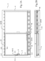
- FIGS 1A and 1B show a front and sectional view of a conventional sliding window 100.
- a sliding sash 102 of the sliding window is shown in the frame 104 in a closed position.
- the sliding sash 102 is provided with a glass 106 and has a handle 110 with which the sash 102 can be pushed open or closed.
- a non-sliding part of the window has a larger glass surface 108 and is therefore not visible.
- the guides here are designed as plastic rails with low friction, and the seals are designed as brush seals, which allow the window sash to be moved even when the seals are in place.
- Figure 1B shows a sectional view of the conventional sliding window with closed sliding window sash 102, wherein the sliding window sash 102 is shown in dashed lines in an open position.
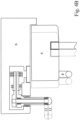
- Figures 2A and 2B show a front partial sectional view and a horizontally sectioned sectional view of a sliding window or sliding door 2 according to the present invention.
- the sliding window/door wing 4 is provided with a lower guide element 20 which is designed as a rail 40.
- the sliding window/door wing 4 is further provided with an upper guide element 22 which is designed as a U-rail 42.
- the sliding window/door frame 6 is provided with a lower guide 24, which is designed as a roller rail 44 with guide rollers 46 and on which the rail 40 of the sliding window/door leaf 4 runs.
- the frame is further provided with an upper guide 26, which is designed here as a series of rollers 48, which are located in the U-rail 42 and guide the sliding window/door leaf 4 at the top.
- the sliding window/door wing 4 can be opened and closed using a handle 8.
- a control element 10 in the form of a control lever 12 is also attached to the frame.
- Figure 2A the opened sliding window/door sash 4 is shown in dashed lines.
- FIG 2B is a sectional view through the sliding window or sliding door 2 of Figure 2A at the height of the handle 8.
- the sliding window/door wing 4 is shown in a closed position.
- the lower guide 24 can be seen, which can be seen as a roller rail 44 with the rollers 50.
- the extended and the opened sliding window/door wing 4 are each shown in dashed lines. Since the tilted or extended position hardly differs from the closed and blocked position, instead of a full arrow, there is only a triangle that indicates that the window or sliding door is extended.
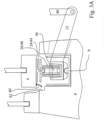
- Figure 3A shows a section along the line and the Figure 3B shows a partial sectional view along line 3-3 of Figure 2A , this view shows the lower part of the sliding sash 4 and the frame 6.
- the section shows a lower part of the sliding window/door frame 6 in which the lower guide 24 is shown in the form of the roller rail 42 in which a guide roller 46 is visible.
- the roller rail 42 can be rotated or pivoted about a lower joint 80, as shown in the Figure 3B In the sliding position or the tilted or extended position, the roller rail is vertical and the rollers of the roller rail can roll on the rail 40 without significant resistance when the sliding window/door sash 4 is moved.
- part of the window sash can be provided with a separate tilt mechanism that allows part of the window sash to be tilted. It may also be provided to increase an adjustment range of the upper guide element and/or the upper guide to such an extent that a tilt window function is provided with a wide gap between the upper edge of the door/window sash and the frame.
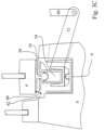
- FIG 3B This shows the section of the sliding window or sliding door of Figure 3A , whereby the lower guide 24 or the roller rail is shown in a tilted position, so that the contact area of the guide rollers 46 is shifted further towards the frame 6 of the sliding window or sliding door, and the seal 60 is in contact with the sealing surface 62.
- the closed and closed position of the sliding sash 4 can be seen. Due to the pivoted position of the roller rail 42, the closed state is stabilized by the weight force acting on the sliding sash. It can also be provided to fix the sliding window/door sash in the closed position by a separate lock.
- the position of the sliding window/door sash is Figure 3A thinner and with dashed lines also in the Figure 3B indicated. The tilting is controlled by the operating lever 12.
- Figure 3C shows a sectional view through another embodiment, which largely corresponds to the design of the Figures 3A and 3B In contrast to the execution of the Figures 3A and 3B
- the lower guide 24 is designed as a sliding element 54 or sliding bearing.
- the sliding element 54 is designed here as a continuous channel made of PTFE (polytetrafluoroethylene), also known as Teflon. This sliding element 54 can also be provided with graphite inserts or other solid or dry lubricants.
- a rail is arranged in the sliding element as the lower guide element 20.
- the rail and the sliding element 54 have, in comparison to the design of the Figures 3A and 3B a larger contact area to keep the surface load between the rail and the sliding element as small as possible.
- the rail can be made of polished stainless steel or aluminum to avoid corrosion.
- the sliding element 54 can be tilted by operating the operating lever in order to close the window sash 4 on a lower side. All other aspects of the window correspond to the Figures 3A and 3B .
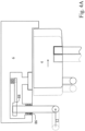
- Figures 4A and 4B show a partial sectional view along line 3-3 of Figure 2A , each showing two different embodiments.
- the Figure 4A shows a design for an operating lever 12 which is arranged on the sliding window/door frame 6.
- the operating lever 12 is arranged with a bearing 86 in the sliding window/door frame 6 and can be pivoted perpendicular to the window/door surface.
- a lever arm 88 is connected to two push rods 80 which run vertically downwards and upwards to the plane of the drawing. When the operating lever 12 is actuated, the lever arm 88 is rotated vertically to the plane of the drawing and two push rods 80 are moved.
- a push rod 80 running downwards into the image plane is moved upwards when the operating lever 12 is pivoted from an obliquely downward position into a vertical position.
- the operating lever 12 extends downwards from the axis mounted in the bearings 86. If the operating lever 12 is rotated downwards from an obliquely forward position into a vertical position, the push rod 80 is pulled upwards and presses the window/door sash 4 into a closed position.
- a second push rod 80 is pushed upwards and is attached to an upper guide, with which in the Figures 5 to 7 components shown also bring the window/door sash into a closed position.
- Figure 4B represents a variant in which the operating lever is split in two, and thus comprises a part that allows only the downward-running push rod 80 to be adjusted and a further part that only adjusts the upward-running push rod 80.
- the sliding window/door wing 4 can be opened either only at the top or only at the bottom or at the top and bottom at the same time.
- the two parts of the operating lever are arranged directly next to each other, so that it is easy to grasp and adjust both parts of the operating lever 12 at the same time.
- Such an adjustment option is not yet known for sliding windows or sliding doors.
- Figures 5A and 5B represent a sectional view through an upper right corner of the window or door of Figure 2A , whereby the Figure 5A represents a deflection of a rod mechanism with a triangular lever 82.
- the vertically extending push rod In one position, the vertically extending push rod is in a lower position (dashed) and in the solid version, the rod is in an upper position (solid). This corresponds to the position of the lever in the Figures 4A and 4B .
- the reversing lever 82 In the upper position, the reversing lever 82 is pivoted and moves a second horizontal push rod 80 analogously to the vertical push rod 80.
- Other deflection mechanisms such as racks and gears could also be used here, but at least a mechanical design is specified here.
- the Figure 5B is a sectional view of the Figure 5A or 2A cut along the line 5-5.
- Figures 6A and 6B show a partial sectional view along line 6-6 of Figure 2A , this view shows a control of an upper guide in the frame.
- the section runs parallel to the section 5-5 of the Figure 5A However, it shows a view of an adjustment of the upper guide, which is implemented here by rollers 48 with vertical roller axes 50.
- the rollers 48 run in a U-shaped rail 42, which is attached to the Sliding window/door wing 4 is attached and serves as the upper guide element 22.
- the push rod moves perpendicular to the image plane in the view.
- the roller axes are attached to deflection levers 84, each with a roller, so that a displacement of the push rod leads to a tilting of the lever and a displacement of the rollers in the image plane.
- the displacement of the roller axes also causes a displacement of the U-shaped rail 42 and thus an adjustment or setting up of the sliding window/door wing 4 relative to the sliding window/door frame 6.
- Lines 7-7 are drawn, which represent cutting lines along which the window or door for the representation of the Figures 7A and 7B are cut.
- rollers are used that run in a U-rail.
- the upper rollers are only used to guide the upper part of the sliding window/door sash laterally.
- There is almost no force on the rollers here because the window is essentially vertical or is only slightly tilted.
- the rollers of the figure can also be replaced with PTFE cylinders or appropriately shaped sliding blocks or sliding elements that run in the U-rail. It is also conceivable to use only a single rail and to use n-shaped sliding blocks that can support a single rail from both sides.
- Figures 7A and 7B each show a sectional view through the mechanism for extending the upper guide by adjusting the rollers on the upper sliding window/door frame 6.
- the sliding window/door sash 4 is shown in a raised position.
- the deflection lever 86 with the roller 48 is extended and holds the Sliding window/door wing 4 away from the sliding window/door frame 6.
- the roller 48 only guides the sliding window/door wing 4 and is not able to bear the weight of the sliding window/door wing 4.
- the push rod 80 is shifted to the right and, by pivoting the lever 86, the roller 48 is pressed closer to the frame 6 until the seal (not shown) rests against an associated sealing surface and seals the window or door.
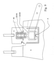
- Figure 8A shows a sectional view of another embodiment of a sliding window or a sliding door, whereby the lower guide element 20, which is designed here as a rail 40, can be pivoted about a pivot axis 30 by two hydraulic cylinders 40 on the sliding wing by means of hydraulic cylinder actuators 90.
- the principle of Figure 3A vice versa, whereby the opening and closing is carried out on the lower guide element, and the frame merely provides a roller rail to be able to open and close the extended sliding window or sliding door.
- Figure 8B shows a sectional view similar to that of the Figure 4B corresponds, whereby an operating lever on the sliding window/door leaf 4 controls hydraulic actuation cylinders 92 via actuation levers, which are connected via hydraulic lines to the hydraulic cylinder actuators 90 on the lower guide element 20.
- a second set of hydraulic cylinder actuators is provided at the top of the sliding window/door leaf 4 in order to adjust guide rollers or a guide rail.
- FIGS. 8A and 8B show possibilities for movement and power transmission that have not previously been common in the area of windows or doors, and in particular sliding windows and sliding doors.
- an electrical control element or electrical control elements on the frame or on the sash with electrical actuators to open the sliding window or sliding door at the top and/or bottom, whereby it is also possible to open or close the sliding window or sliding door using another electrical actuator and to lock it if necessary.
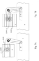
- Figure 9 represents a further possibility for adjusting a lower guide 24, which is designed here as a rail 40, arranged in the frame 6 of a sliding window or a sliding door.
- the rail 40 works together with a roller rail 44 which is embedded in the sliding window/door wing 4.
- the roller rail 44 serves as a lower guide element 20.
- This design requires a larger frame of the sliding window/door wing 4 in order to be able to accommodate at least the diameter of the guide rollers 46.
- An advantage of the design of Figure 9 is that all guide rollers 46 run permanently on the rail 40 and so no running up and down of one end of the rail 40 on a guide roller 46 occurs, which could hinder a sliding movement.
- the execution of the Figure 9 allows, provided that the upper guide elements in the sliding window/door wing 4 are also designed as rollers, an opening or closing movement that can be completely smooth.
- the design of the Figure 9 also allows the number of guide rollers 44 to be reduced significantly, since there is no running of rollers onto or off a rail end.
- Figure 10 provides another possibility for adjusting a lower guide 24.
- the lower guide 24, here as in Figure 3A designed as a roller rail 44 is embedded in the lower frame 6 of the sliding window or sliding door.
- the rail 40 which is attached to the sliding window/door wing 4 as a lower guide element, is wider and essentially flat.
- the guide rollers 46 of the roller rail 44 have also has a running surface with a flat profile that can carry higher loads than the guide rollers of the other versions.
- an operating element 10 is designed as an operating lever 12 (where a push rod is not shown).
- the operating lever 12 is connected to a parallel four-bar mechanism that enables a parallel displacement of the roller rail 44 on a circular arc.
- the parallel displacement can be designed symmetrically here, so that the mechanism and the sliding window/door wing 4 assume a stable position under the influence of gravity both in the closed position and in an open position, in which there is no load on the adjustment mechanism.
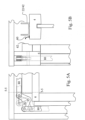
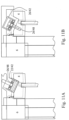
- Figures 11A and 11B show a possibility to extend or close the upper part of a window or door wing without the need for a separate mechanism.
- the upper guide 26 is designed as a series of rollers 48 which run in an upper guide element 22 which is designed as a U-rail.
- the rollers are designed as inclined rollers 52 and which run in an inclined rail 50.
- the inclined rollers 52 run on an upper edge of the inclined rail 50. If the window or door sash 4 is raised, the inclined rollers move further into the inclined rail 50 and press the window or door sash 4 away from the window or door frame 6.
- the window or door sash 4 can be raised in order to expose the upper part of the window or door sash 4.
- Figure 11B corresponds in principle to the execution of the Figure 11A , whereby only the upper guide 26 is designed as a U-rail and the upper guide element 22 is designed as a series of rollers 48 that run in the U-rail.
- the rollers are designed as inclined rollers 52 and run in an inclined rail 50.
- the inclined rollers 52 run on an upper edge of the inclined rail 50, and the window or door leaf 4 is at least closed on the upper side. If the window or door leaf 4 is raised, the Inclined rollers 52 move further into the inclined rail 50 and push the window or door leaf 4 away from the window or door frame 6.
- the window or door leaf 4 can be lifted in order to expose the upper part of the window or door leaf 4.
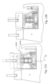
- Figure 12 A and 12B represent an embodiment of a mechanism that is particularly advantageous with the mechanism of the Figures 11A and 11B
- the window sash is essentially pivoted parallel on a quarter circle, which creates a movement that initially lifts the window/door sash 4, whereby the upper part of the window with the inclined rollers and inclined rails is also pushed outwards and thus opened. During this movement, the lower part of the window sash is opened and closed again.
- the Figure 12B It is shown how the lower guide can be moved outwards without lifting the window sash.
Landscapes
- Engineering & Computer Science (AREA)
- Mechanical Engineering (AREA)
- Support Devices For Sliding Doors (AREA)
Priority Applications (1)
| Application Number | Priority Date | Filing Date | Title |
|---|---|---|---|
| EP23160988.4A EP4428331B1 (fr) | 2023-03-09 | 2023-03-09 | Porte ou fenêtre coulissante |
Applications Claiming Priority (1)
| Application Number | Priority Date | Filing Date | Title |
|---|---|---|---|
| EP23160988.4A EP4428331B1 (fr) | 2023-03-09 | 2023-03-09 | Porte ou fenêtre coulissante |
Publications (3)
| Publication Number | Publication Date |
|---|---|
| EP4428331A1 true EP4428331A1 (fr) | 2024-09-11 |
| EP4428331B1 EP4428331B1 (fr) | 2025-10-22 |
| EP4428331C0 EP4428331C0 (fr) | 2025-10-22 |
Family
ID=85569672
Family Applications (1)
| Application Number | Title | Priority Date | Filing Date |
|---|---|---|---|
| EP23160988.4A Active EP4428331B1 (fr) | 2023-03-09 | 2023-03-09 | Porte ou fenêtre coulissante |
Country Status (1)
| Country | Link |
|---|---|
| EP (1) | EP4428331B1 (fr) |
Citations (7)
| Publication number | Priority date | Publication date | Assignee | Title |
|---|---|---|---|---|
| DE2303682A1 (de) * | 1973-01-26 | 1974-08-01 | Alco Bauzubehoer | Schiebefenster, schiebetuer oder dgl |
| FR2300879A1 (fr) * | 1975-02-14 | 1976-09-10 | Devilca Fb | Porte-fenetre coulissante |
| DE3639998A1 (de) * | 1986-11-22 | 1988-06-01 | Siegenia Frank Kg | Beschlag fuer einen parallelabstellbaren horizontalschiebefluegel von fenstern, tueren od. dgl. |
| US5836111A (en) * | 1996-04-16 | 1998-11-17 | Fine Industries, Inc. | Opening-closing device for windows |
| DE19948376A1 (de) * | 1998-10-07 | 2000-06-29 | Hautau Gmbh W | Flügelaufhängung für verfahrbaren Abstellflügel |
| EP2317054A2 (fr) * | 2009-11-02 | 2011-05-04 | Dieter Blösch | Porte coulissante |
| WO2019168840A1 (fr) * | 2018-02-27 | 2019-09-06 | Arconic Inc. | Système de porte coulissante |
-
2023
- 2023-03-09 EP EP23160988.4A patent/EP4428331B1/fr active Active
Patent Citations (7)
| Publication number | Priority date | Publication date | Assignee | Title |
|---|---|---|---|---|
| DE2303682A1 (de) * | 1973-01-26 | 1974-08-01 | Alco Bauzubehoer | Schiebefenster, schiebetuer oder dgl |
| FR2300879A1 (fr) * | 1975-02-14 | 1976-09-10 | Devilca Fb | Porte-fenetre coulissante |
| DE3639998A1 (de) * | 1986-11-22 | 1988-06-01 | Siegenia Frank Kg | Beschlag fuer einen parallelabstellbaren horizontalschiebefluegel von fenstern, tueren od. dgl. |
| US5836111A (en) * | 1996-04-16 | 1998-11-17 | Fine Industries, Inc. | Opening-closing device for windows |
| DE19948376A1 (de) * | 1998-10-07 | 2000-06-29 | Hautau Gmbh W | Flügelaufhängung für verfahrbaren Abstellflügel |
| EP2317054A2 (fr) * | 2009-11-02 | 2011-05-04 | Dieter Blösch | Porte coulissante |
| WO2019168840A1 (fr) * | 2018-02-27 | 2019-09-06 | Arconic Inc. | Système de porte coulissante |
Also Published As
| Publication number | Publication date |
|---|---|
| EP4428331B1 (fr) | 2025-10-22 |
| EP4428331C0 (fr) | 2025-10-22 |
Similar Documents
| Publication | Publication Date | Title |
|---|---|---|
| EP3063354B1 (fr) | Charnière pour plaque de cuisson | |
| EP0717684B1 (fr) | Dispositif permettant de guider une plaque de toit ouvrant de vehicule | |
| DE9007595U1 (de) | Vorrichtung zum Niederholen des freien Endes eines Fahrzeugverdecks o.dgl. | |
| EP3405359B1 (fr) | Agencement avec couvercle pour toit de véhicule | |
| DE102008032750A1 (de) | Beschlag für kraftbetätigte Parallelausstellfenster | |
| DE102005002180B4 (de) | Elektromotorische Vertikal-Steuervorrichtungfür einen Hebe-Schiebeflügel | |
| DE102011085177B4 (de) | Antriebssystem für ein KFZ-Dachsystem | |
| EP3507161A1 (fr) | Dispositif permettant de rendre étanche au moins un vantail de porte d'un véhicule ferroviaire et véhicule ferroviaire | |
| EP1266115B1 (fr) | Unite ferrure pour une fenetre ou une porte | |
| DE202013009586U1 (de) | Beschlag für Fenster, Türen oder dergleichen | |
| EP4428331B1 (fr) | Porte ou fenêtre coulissante | |
| EP0096744A2 (fr) | Ferrure pour battant oscillo-battant | |
| EP3385485A1 (fr) | Ferrure de meuble pour un mouvement combiné coulissant et pivotant d'une porte en plusieurs parties et meuble doté d'une telle ferrure de meuble | |
| DE2658626C3 (de) | Schaltsperre für Treibstangenbeschläge | |
| EP0905343B1 (fr) | Agencement de fenêtre ou de porte | |
| EP0697054B1 (fr) | Dispositif permettant d'orienter des fenetres basculantes et pivotantes | |
| EP2143859A2 (fr) | Système de verouillage | |
| EP1522666B1 (fr) | Ferrure pour portes ou fenêtres à soulèvement et coulissement et chariot pour un tel ferrure. | |
| EP1662204B1 (fr) | Porte de cheminée | |
| CH711522A2 (de) | Vorrichtung zur automatischen Betätigung eines Flügels einer Hebe-Schiebetür. | |
| EP1798361B1 (fr) | Porte | |
| DE2639954C2 (de) | Ausstellvorrichtung für Kippflügel von Fenstern oder Türen | |
| WO2021023381A1 (fr) | Ensemble accessoire pour une fenêtre, coulisseau pour un ensemble accessoire et fenêtre | |
| EP4386163B1 (fr) | Agencement de porte coulissante | |
| EP0204057B1 (fr) | Fenêtre coulissant verticalement |
Legal Events
| Date | Code | Title | Description |
|---|---|---|---|
| PUAI | Public reference made under article 153(3) epc to a published international application that has entered the european phase |
Free format text: ORIGINAL CODE: 0009012 |
|
| STAA | Information on the status of an ep patent application or granted ep patent |
Free format text: STATUS: THE APPLICATION HAS BEEN PUBLISHED |
|
| AK | Designated contracting states |
Kind code of ref document: A1 Designated state(s): AL AT BE BG CH CY CZ DE DK EE ES FI FR GB GR HR HU IE IS IT LI LT LU LV MC ME MK MT NL NO PL PT RO RS SE SI SK SM TR |
|
| STAA | Information on the status of an ep patent application or granted ep patent |
Free format text: STATUS: REQUEST FOR EXAMINATION WAS MADE |
|
| 17P | Request for examination filed |
Effective date: 20241010 |
|
| RBV | Designated contracting states (corrected) |
Designated state(s): AL AT BE BG CH CY CZ DE DK EE ES FI FR GB GR HR HU IE IS IT LI LT LU LV MC ME MK MT NL NO PL PT RO RS SE SI SK SM TR |
|
| GRAP | Despatch of communication of intention to grant a patent |
Free format text: ORIGINAL CODE: EPIDOSNIGR1 |
|
| STAA | Information on the status of an ep patent application or granted ep patent |
Free format text: STATUS: GRANT OF PATENT IS INTENDED |
|
| INTG | Intention to grant announced |
Effective date: 20250702 |
|
| GRAS | Grant fee paid |
Free format text: ORIGINAL CODE: EPIDOSNIGR3 |
|
| GRAA | (expected) grant |
Free format text: ORIGINAL CODE: 0009210 |
|
| STAA | Information on the status of an ep patent application or granted ep patent |
Free format text: STATUS: THE PATENT HAS BEEN GRANTED |
|
| AK | Designated contracting states |
Kind code of ref document: B1 Designated state(s): AL AT BE BG CH CY CZ DE DK EE ES FI FR GB GR HR HU IE IS IT LI LT LU LV MC ME MK MT NL NO PL PT RO RS SE SI SK SM TR |
|
| REG | Reference to a national code |
Ref country code: CH Ref legal event code: F10 Free format text: ST27 STATUS EVENT CODE: U-0-0-F10-F00 (AS PROVIDED BY THE NATIONAL OFFICE) Effective date: 20251022 Ref country code: GB Ref legal event code: FG4D Free format text: NOT ENGLISH Ref country code: CH Ref legal event code: R17 Free format text: ST27 STATUS EVENT CODE: U-0-0-R10-R17 (AS PROVIDED BY THE NATIONAL OFFICE) Effective date: 20251022 |
|
| REG | Reference to a national code |
Ref country code: IE Ref legal event code: FG4D Free format text: LANGUAGE OF EP DOCUMENT: GERMAN |
|
| U01 | Request for unitary effect filed |
Effective date: 20251022 |
|
| U07 | Unitary effect registered |
Designated state(s): AT BE BG DE DK EE FI FR IT LT LU LV MT NL PT RO SE SI Effective date: 20251028 |
|
| REG | Reference to a national code |
Ref country code: CH Ref legal event code: U11 Free format text: ST27 STATUS EVENT CODE: U-0-0-U10-U11 (AS PROVIDED BY THE NATIONAL OFFICE) Effective date: 20260401 |
|
| PG25 | Lapsed in a contracting state [announced via postgrant information from national office to epo] |
Ref country code: ES Free format text: LAPSE BECAUSE OF FAILURE TO SUBMIT A TRANSLATION OF THE DESCRIPTION OR TO PAY THE FEE WITHIN THE PRESCRIBED TIME-LIMIT Effective date: 20251022 |
|
| PG25 | Lapsed in a contracting state [announced via postgrant information from national office to epo] |
Ref country code: NO Free format text: LAPSE BECAUSE OF FAILURE TO SUBMIT A TRANSLATION OF THE DESCRIPTION OR TO PAY THE FEE WITHIN THE PRESCRIBED TIME-LIMIT Effective date: 20260122 |
|
| PG25 | Lapsed in a contracting state [announced via postgrant information from national office to epo] |
Ref country code: HR Free format text: LAPSE BECAUSE OF FAILURE TO SUBMIT A TRANSLATION OF THE DESCRIPTION OR TO PAY THE FEE WITHIN THE PRESCRIBED TIME-LIMIT Effective date: 20251022 |
|
| PG25 | Lapsed in a contracting state [announced via postgrant information from national office to epo] |
Ref country code: RS Free format text: LAPSE BECAUSE OF FAILURE TO SUBMIT A TRANSLATION OF THE DESCRIPTION OR TO PAY THE FEE WITHIN THE PRESCRIBED TIME-LIMIT Effective date: 20260122 |
|
| PG25 | Lapsed in a contracting state [announced via postgrant information from national office to epo] |
Ref country code: IS Free format text: LAPSE BECAUSE OF FAILURE TO SUBMIT A TRANSLATION OF THE DESCRIPTION OR TO PAY THE FEE WITHIN THE PRESCRIBED TIME-LIMIT Effective date: 20260222 |
|
| PG25 | Lapsed in a contracting state [announced via postgrant information from national office to epo] |
Ref country code: PL Free format text: LAPSE BECAUSE OF FAILURE TO SUBMIT A TRANSLATION OF THE DESCRIPTION OR TO PAY THE FEE WITHIN THE PRESCRIBED TIME-LIMIT Effective date: 20251022 |