EP4431408A1 - Corps de canette - Google Patents
Corps de canette Download PDFInfo
- Publication number
- EP4431408A1 EP4431408A1 EP22903822.9A EP22903822A EP4431408A1 EP 4431408 A1 EP4431408 A1 EP 4431408A1 EP 22903822 A EP22903822 A EP 22903822A EP 4431408 A1 EP4431408 A1 EP 4431408A1
- Authority
- EP
- European Patent Office
- Prior art keywords
- dome
- axis
- recess
- ground
- barrel
- Prior art date
- Legal status (The legal status is an assumption and is not a legal conclusion. Google has not performed a legal analysis and makes no representation as to the accuracy of the status listed.)
- Pending
Links
Images


Classifications
-
- B—PERFORMING OPERATIONS; TRANSPORTING
- B65—CONVEYING; PACKING; STORING; HANDLING THIN OR FILAMENTARY MATERIAL
- B65D—CONTAINERS FOR STORAGE OR TRANSPORT OF ARTICLES OR MATERIALS, e.g. BAGS, BARRELS, BOTTLES, BOXES, CANS, CARTONS, CRATES, DRUMS, JARS, TANKS, HOPPERS, FORWARDING CONTAINERS; ACCESSORIES, CLOSURES, OR FITTINGS THEREFOR; PACKAGING ELEMENTS; PACKAGES
- B65D1/00—Rigid or semi-rigid containers having bodies formed in one piece, e.g. by casting metallic material, by moulding plastics, by blowing vitreous material, by throwing ceramic material, by moulding pulped fibrous material or by deep-drawing operations performed on sheet material
- B65D1/12—Cans, casks, barrels, or drums
- B65D1/14—Cans, casks, barrels, or drums characterised by shape
- B65D1/16—Cans, casks, barrels, or drums characterised by shape of curved cross-section, e.g. cylindrical
- B65D1/165—Cylindrical cans
Definitions
- the present invention relates to a can body, and specifically to a can body having a reformed can bottom.
- a drawn and ironed can made of aluminum alloy (two-piece can) as a container filled with contents such as beverage .
- the can body of a drawn and ironed can made of aluminum alloy is obtained by punching a circular plate out of a plate material made of aluminum alloy and drawing the circular plate, and therefore to mold a shallow cup member having a bottomed cylindrical shape. Then, the cup member is redrawn and ironed to integrally mold a can bottom and a can barrel.
- This can body is required to reduce the plate thickness of the can barrel in the light of resource saving.
- the can bottom is designed to have a sufficient pressure strength even through the can body is formed to be thinner.
- the can bottom includes a dome part whose center part being concave to the inside of the can body, and an annular convex part formed around the dome part, and bottom reforming is applied to the annular convex part to secure the pressure strength against the thinning (for example, Patent Literature 1) .
- the can body is required to have a sufficient drop strength against the drop impact, in order to be distributed to the market (for example, Patent Literature 2) .
- a slim two-piece can having a smaller diameter has been increasingly popular because of its stylish design, instead of a general two-piece can (211 diameter) containing beer and so forth (for example, Patent Literature 3) .
- a general two-piece can (211 diameter) containing beer and so forth for example, Patent Literature 3 .
- the bottom reforming to deform the annular convex part into the can body as described above, when the can body after the bottom reforming is filled with content, the liquid level of the content is raised even though the amount of content is not changed before the bottom reforming. This affects the filling amount of the content.
- the can body having a small diameter such as the 204 diameter is more affected than the can body having 211 diameter.
- the present invention has been achieved considering the above-described circumstances to address the above-described problem. It is therefore an object of the invention to secure the pressure strength and the drop strength while securing a predetermined filling amount of the content.
- An aspect of the present invention provides a can body made of aluminum alloy and having a bottomed cylindrical shape including: a can bottom; and a can barrel having a cylindrical shape around a can axis and extending from an outer circumference of the can bottom along the can axis.
- the can bottom includes a dome part provided in a center of the can bottom, and an annular convex part continuing to an outer circumferential edge of the dome part and circumferentially projecting to an outside of the can body along a can axis direction.
- the annular convex part includes a recess provided to continue to the dome part and having a curved surface being convex to the outside of the can body in a radial direction, a ground part configured to support the can body, and an inner circumferential wall extending from the ground part to the recess.
- An outer diameter of the can barrel is 50 mm to 59 mm, and a can height from the ground part to an upper end of the can barrel is 120 mm to 190 mm.
- a recess depth is 0.5 mm to 0.9 mm, and a ground diameter is ⁇ 44.0 mm to 47.0 mm in a vertical cross-sectional view including the can axis.
- the recess depth is a distance between a portion of the recess on an outer surface of the can body which is the farthest from the can axis and a portion of the ground part on the outer surface of the can body which is the closest to the can axis in the radial direction.
- the ground diameter is a diameter of a most projecting portion of the ground part facing downward in the can axis direction.
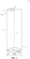
- Fig. 1 is a vertical cross-sectional view along a can axis O of a can body 10 and schematically illustrates the can body 10.
- Fig. 1 is a diagrammatic drawing illustrating the cross-sectional shape of the can body 10 without the plate thickness of the can body 10.
- the can body 10 has a bottomed cylindrical shape including a can bottom 11, and a can barrel 12 having a cylindrical shape around a can axis O and extending from the outer circumference of the can bottom 11 along the can axis O.
- the can bottom 11 includes a dome part 111 and an annular convex part 112.
- the dome part 111 is provided in the center of the can bottom 11, and the annular convex part 112 continues from the outer circumferential edge of the dome part 11 and circumferentially projects to the outside of the can body 10 along the direction of the can axis O to support the can body 10.
- the annular convex part 112 is provided to continue to the dome part 111, and includes a recess 112A having a curved surface which is convex to the outside of the can body 10 in the radial direction, a ground part 112B configured to support the can body 10, and an inner circumferential wall 112C extending from the ground part 112B to the recess 112A (see Fig. 2 ) .
- the can body according to an embodiment of the invention is, for example, a drawn and ironed can made of aluminum alloy.
- the can body according to the embodiment is a drawn and ironed can made of aluminum alloy having the configuration like the can body 10 illustrated in Fig. 1 , and the shape and the size of each of the parts are optimized. Therefore, hereinafter, the shape and the size of the can body 10 as a drawn and ironed can made of aluminum alloy according to the embodiment will be descried, with reference to Fig. 1 and so forth.
- the can body 10 as a drawn and ironed can made of aluminum alloy is obtained by, for example: punching a circular plate out of a plate material made of aluminum alloy; drawing the circular plate to mold a cup member having a bottomed cylindrical shape; redrawing and ironing the cup member to integrally mold the can bottom 11 and the can barrel 12; and trimming, necking and flanging the opening end of the can barrel 12.
- the can body 10 includes the can bottom 11, and the can barrel 12 having a cylindrical shape around the can axis O and extending from the outer circumference of the can bottom 11 along the can axis O.
- the can body 10 has a bottomed cylindrical shape formed by the can bottom 11 and the can barrel 12.
- the can bottom 11 and the can barrel 12 have the same shape along the entire circumference around the can axis O.
- the height of the can body 10 from the ground part (described later) of the can bottom 11 to the upper end of the can barrel 12 is 120 mm to 190 mm. With the example illustrated in Fig. 1 , the can height is 155.0 mm.
- the outer diameter of the can barrel 12 is 50 mm to 59 mm. With the example illustrated in Fig. 1 , the outer diameter is 57.2 mm.
- Fig. 2 is an enlarged cross-sectional view illustrating the can bottom 11.
- Fig. 2 is a partial enlarged cross-sectional view illustrating the can bottom 11 illustrated in Fig. 1 .
- the can bottom 11 includes the dome part 111 and the annular convex part 112.
- the dome part 111 is provided in the center of the can bottom 11, and has a plurality of curved surfaces including a concave curved surface like a dome which is concave into the can barrel 12 along the direction of the can axis O.
- the dome part 111 includes two curved surfaces including a first dome 111A and a second dome 111B, and a tapered part 111C.
- the first dome 111A is formed in the center of the can bottom 11, and includes a concave curved surface being concave into the can barrel 12 along the direction of the can axis O and having a radius of curvature R1.
- the second dome 111B is located around the first dome 111A and provided outside of the first dome 111A in the radial direction to continue to the outer circumferential edge of the first dome 111A, and includes a concave curved surface being concave into the can barrel 12 and having a radius of curvature R2.
- the radius of curvature R2 of the second dome 111B is smaller than the radius of curvature R1 of the first dome 111A.
- the thickness of the aluminum alloy of the first dome 111A on the can axis O is 0.18 mm to 0.26 mm.
- thickness of aluminum alloy is 0.18 mm to 0.26 mm.
- the thickness of aluminum alloy is excessively small, the possibility of cracking the can barrel is increased in the process of redrawing and ironing, and therefore the yield rate may be decreased.
- the thickness of aluminum alloy is excessively large, the amount of material to be used is increased. Therefore, both cases fail to meet the request for resource saving. Accordingly, the thickness of aluminum alloy is within the above-described range, and consequently it is possible to thin the can body to attempt the resource saving, and prevent the can barrel from being cracked to improve the yield rate.
- the dome part 111 may have a plurality of curved surfaces with different radius of curvatures as the example illustrated in Fig. 1 .
- the curved surface may have a radius of curvature varying gradually and smoothly, as well as the curved surface having a fixed radius of curvature.
- a well-known dome shape is applicable.
- the tapered part 111C is a surface provided on the outer circumferential part of the second dome 111B. One end of the tapered part 111C continues to the outer circumferential edge of the second dome 111B, and the other end continues to the recess 112A described later. By this means, the diameter of the tapered part 111C is gradually increased from the second dome 111B to the recess 112A.
- the tapered part 111C may be a straight line in a vertical cross-sectional view including the can axis O, or a curved surface projecting to the inside or the outside of the can body 10.
- the annular convex part 112 circumferentially projects from the outer circumferential edge of the dome part 111 to the outside of the can body 10 along the direction of the can axis O.
- the annular convex part 112 includes the recess 112A, the ground part 112B, and the inner circumferential wall 112C.
- the recess 112A is provided to continue to the outer circumferential edge of the dome part 111, and includes a curved surface being convex to the outside of the can body 10 in the radial direction. It is preferred that the radius of curvature of the curved surface of the recess 112A is 0.3 mm to 1.2 mm.
- the height of the recess 112A that is, a distance between a ground portion 113 of the ground part 112B (the most projecting portion of the ground part 112B facing downward in the direction of the can axis O and contacting a ground plane G) and the portion of the recess 112A on the outer surface of the can body 10 which is the farthest from the can axis O in the radial direction is 1 mm to 4 mm.
- the recess 112A may have a plurality of curved surfaces having different radius of curvatures of 0,3 mm to 1,2 mm.
- the ground part 112B includes two convex curved surfaces on both sides sandwiching the ground portion 113.
- the ground part 112B includes a first convex curved surface 113A formed on a side close to the can axis O and a second convex curved surface 113B formed on a side far from the can axis O, with respect to the ground portion 113.
- a radius of curvature R3 of the first convex curved surface 113A is 0.4 mm to 0,7 mm
- a radius of curvature R4 of the second convex curved surface 113B is 1.6 mm to 2.2 mm.
- the inner circumferential wall 112C is provided between the ground part 112B and the recess 112A, and inclined to gradually decrease the diameter of the inner circumferential wall 112C from the recess 112A to the ground part 112B along the direction of the can axis O. It is preferred that the angle of inclination of the inner circumferential wall 112C, that is, the angle formed between the inner circumferential wall 112C and the can axis O is 15 degrees to 30 degrees.
- the annular convex part 112 is formed to have a recess depth of 0.5 mm to 0.9 mm and a ground diameter of ⁇ 44.0 mm to 47.0 mm, in a vertical cross-sectional view including the can axis O illustrated in Fig. 1 .
- a recess depth d1 is a distance between the portion of the recess 112A on the outer surface of the can body 10 which is the farthest from the can axis O and the portion of the ground part 112B on the outer surface of the can body 10 which is the closest to the can axis O in the radial direction.
- the ground diameter is the diameter of the ground portion 113 of the ground part 112B.
- the recess depth d1 is 0.7 mm
- the ground diameter is ⁇ 45.5 mm.
- the can barrel 12 has a cylindrical shape around the can axis O and extends from the outer circumference of the can bottom 11 along the can axis O.
- a neck 121 is provided in the upper end of the can barrel 12 and formed such that the outer diameter of the can barrel 12 is gradually decreased toward the top of the can barrel along the can axis O.
- a can lid (not illustrated) having a diameter smaller than that of the can barrel 12 is provided in the neck 121.
- the minimum outer diameter of the neck 121 is 52.4 mm.
- the neck 121 includes a concave curved surface 121A formed on the upper end to be concave into the can body 10 in the radial direction of the can body 10 and having a radius of curvature r1, and a convex curved surface 121B formed on the lower end to be convex to the outside of the can body 10 in the radial direction of the can body 10 and having a radius of curvature r2.
- the neck 121 also includes a concave curved surface 121C formed between the concave curved surface 121A on the upper end and the convex curved surface 121B on the lower end.
- the concave curved surface 121C is concave into the can body 10 in the radial direction of the can body 10 and has a radius of curvature r3.
- a flange 123 is formed on the opening end of the can body 10, that is, on the upper end of the neck 121.
- the radius of curvature r1 is 1.5 mm
- the radius of curvature r2 is 5.0 mm
- the radius of curvature r3 is 10.0 mm.
- the values of the radius of curvatures are merely an example, and are by no means limiting.
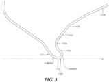
- FIG. 3 is an enlarged view illustrating the can bottom 11 in a vertical cross-sectional view along the can axis O of the can body according to Modification 1 (the can axis O is not illustrated in Fig. 3 ) .
- the radius of curvature of the recess 112A is greater, and the distance of the inner circumferential wall in a vertical cross-sectional view is shorter in the modification, than the can body according to the above-described embodiment.
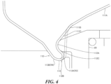
- a predetermined reform roll 20 is used as illustrated in Fig. 4 to apply bottom reforming. That is, the annular convex part extending from the second dome 111B of the dome part 111 to the outside of the can body along the direction of the can axis O is pressed by the reform roll 20 to the outside in the radial direction, and therefore is deformed.
- the recess 112A is formed depending on the shape of the reform roll 20 and the amount of pressing the reform roll 20, the tapered part 111C is formed on the recess 112A, and the inner circumferential wall 112C is formed under the recess 112A.
- Fig. 5 and Fig. 6 are tables illustrating the results of drop tests for the can body 10 with adjusted parts in size.
- Fig. 5 and Fig. 6 illustrate the results of two types of drop tests including "single drop test” and "case drop test”. Each of the drop tests was conducted under the following conditions.
- the can body 10 was filled with 335 ml of carbonated water, sealed with the can lid, sufficiently shaken, and dropped as a single body.
- a drop surface is provided by preparing one piece of material for cardboard cartons for packaging used to transport product cans, and putting the material on a block made of gray cast iron processed to be a flat surface whose top surface has an angle of inclination of 10 degrees.
- the can body 10 freely fell to the drop surface from the height at which the shortest distance from the ground part 112B to the drop surface was 20 cm while the ground part 112B faced downward and the can axis O was along the vertical direction.
- 24 can bodies 10 each of which was filled with 355 ml of carbonated water and sealed with the can lid were accommodated in a rectangular parallelepiped cardboard carton for packaging used to transport product cans, sufficiently shaken, and dropped.
- a drop surface is provided by placing a dull-finished SPCC iron plate having a thickness of 20 mm on a horizontal concrete ground.
- the cardboard carton for packaging freely fell to the drop surface from the height at which the shortest distance from the cardboard carton for packaging to the iron plate was 15 cm, while the ground part 112B of each of the accommodated can bodies 10 faced downward, and the longitudinal direction of the horizontal cardboard carton for packaging was inclined for 20 degrees.
- each of the tables illustrated in Fig. 5 and Fig. 6 lists: "recess depth” denoting a distance between the portion of the recess 112A on the outer surface of the can body 10 which is the farthest from the can axis O and the portion of the ground part 112B on the outer surface of the can body 10 which is the closest to the can axis O in the radial direction; "ground diameter” denoting the diameter of the ground portion 113 of the ground part 112B; “thickness of aluminum alloy” denoting the thickness of the aluminum alloy of the first dome 111A on the can axis O; "can height” denoting the height of the can body from the ground part 112B to the upper end of the can barrel 12; “outer diameter of can barrel” denoting the outer diameter of the can barrel 12; “content specification” including “liquid temperature” and “internal pressure” of the carbonated water filled in the can body 10; and “evaluation” for the deformation of the dome part 111 or the annular conve
- Fig. 5 illustrates the results of drop tests using the can body 10 according to examples and comparative examples where the thickness of the aluminum alloy is 0.22 mm, the can height is 155.3 mm, the recess depth is 0.68 mm, the outer diameter of the can barrel is 57.2 mm, and the ground diameter varies from 43.0 mm to 47.5 mm by 0.5 mm.
- Fig. 6 illustrates the results of drop tests using the can body 10 according to examples and comparative examples where the thickness of the aluminum alloy is 0.22 mm, the can height is 155.3 mm, the ground diameter is 45.4 mm, the outer diameter of the can barrel is 57.2 mm, and the recess depth varies from 0.40 mm to 0.85 mm by 0.5 mm.
- the ground diameter is 43.5 mm (comparative example 1-2)
- the can body 10 having the internal pressure of 500 kPa fails in both the single drop test and the case drop test.
- the ground diameter is 47.5 mm (comparative example 1-3)
- the dome part 111 is not deformed only in the case where the internal pressure is 400 kPa in the case drop test, and the other cases are evaluated as fails.
- the shape and the size of the can body is optimized, and the bottom reforming is applied to the can bottom 11 to make the can bottom 11 have the recess depth of 0.5 mm to 0.8 mm, and the ground diameter of ⁇ 44.0 mm to 47.0 mm.
Landscapes
- Engineering & Computer Science (AREA)
- Ceramic Engineering (AREA)
- Mechanical Engineering (AREA)
- Containers Having Bodies Formed In One Piece (AREA)
- Rigid Containers With Two Or More Constituent Elements (AREA)
- Pressure Vessels And Lids Thereof (AREA)
Applications Claiming Priority (2)
| Application Number | Priority Date | Filing Date | Title |
|---|---|---|---|
| JP2021199850A JP2023085679A (ja) | 2021-12-09 | 2021-12-09 | 缶体 |
| PCT/JP2022/035449 WO2023105888A1 (fr) | 2021-12-09 | 2022-09-22 | Corps de canette |
Publications (2)
| Publication Number | Publication Date |
|---|---|
| EP4431408A1 true EP4431408A1 (fr) | 2024-09-18 |
| EP4431408A4 EP4431408A4 (fr) | 2025-11-26 |
Family
ID=86730078
Family Applications (1)
| Application Number | Title | Priority Date | Filing Date |
|---|---|---|---|
| EP22903822.9A Pending EP4431408A4 (fr) | 2021-12-09 | 2022-09-22 | Corps de canette |
Country Status (6)
| Country | Link |
|---|---|
| US (1) | US20240300687A1 (fr) |
| EP (1) | EP4431408A4 (fr) |
| JP (1) | JP2023085679A (fr) |
| CN (1) | CN118284562A (fr) |
| TW (1) | TW202322933A (fr) |
| WO (1) | WO2023105888A1 (fr) |
Families Citing this family (2)
| Publication number | Priority date | Publication date | Assignee | Title |
|---|---|---|---|---|
| BE1030110B1 (nl) * | 2021-12-27 | 2023-07-25 | Envases Universales de Mexico SAPI de CV | Drankblik |
| JP2025063428A (ja) * | 2023-10-04 | 2025-04-16 | 東洋製罐株式会社 | 缶体、製品缶、及び、缶体の製造方法 |
Family Cites Families (18)
| Publication number | Priority date | Publication date | Assignee | Title |
|---|---|---|---|---|
| US5105973B1 (en) * | 1990-10-22 | 1998-06-02 | Ball Corp | Beverage container with improved bottom strength |
| MX9101632A (es) | 1990-10-22 | 1992-06-05 | Ball Corp | Metodo y aparato para reforzar la base o fondo de un recipiente |
| JPH09285832A (ja) * | 1996-04-23 | 1997-11-04 | Kishimoto Akira | シームレス缶及びその成形法 |
| JP4112137B2 (ja) * | 1998-11-20 | 2008-07-02 | ユニバーサル製缶株式会社 | 缶及びその製造方法 |
| US6296139B1 (en) * | 1999-11-22 | 2001-10-02 | Mitsubishi Materials Corporation | Can manufacturing apparatus, can manufacturing method, and can |
| US7398894B2 (en) | 2003-11-24 | 2008-07-15 | Metal Container Corporation | Container bottom, method of manufacture, and method of testing |
| US7980413B2 (en) * | 2007-07-25 | 2011-07-19 | Crown Packaging Technology, Inc. | Base for metallic container |
| CN202063307U (zh) * | 2011-04-18 | 2011-12-07 | 太平洋制罐(北京)有限公司 | 铝制两片易拉罐 |
| JP2014054999A (ja) * | 2012-09-11 | 2014-03-27 | Kirin Brewery Co Ltd | 2ピース缶 |
| CN203903013U (zh) | 2014-03-03 | 2014-10-29 | 上海宝钢包装股份有限公司 | 一种250ml容量钢制两片易拉罐 |
| JP6448217B2 (ja) * | 2014-05-08 | 2019-01-09 | ユニバーサル製缶株式会社 | 缶 |
| JP6713741B2 (ja) * | 2014-08-20 | 2020-06-24 | ユニバーサル製缶株式会社 | 缶 |
| WO2017008961A1 (fr) * | 2015-07-14 | 2017-01-19 | Ball Europe Gmbh | Boîte-boisson en aluminium |
| FR3063975B1 (fr) * | 2017-03-15 | 2019-03-22 | Ardagh Mp Group Netherlands B.V. | Corps de boite pour la fabrication d'une boite de conserve destinee a recevoir un produit alimentaire sterilise par un traitement thermique |
| ES3055184T3 (en) * | 2019-01-30 | 2026-02-10 | Toyo Seikan Group Holdings Ltd | Seamless can body and method for producing seamless can body |
| JP7818890B2 (ja) * | 2019-08-19 | 2026-02-24 | アルテミラ製缶株式会社 | 缶体 |
| JP7447564B2 (ja) * | 2020-03-09 | 2024-03-12 | 東洋製罐グループホールディングス株式会社 | シームレス缶体及びシームレス缶体の製造方法 |
| US12343782B2 (en) * | 2020-03-18 | 2025-07-01 | Toyo Seikan Co., Ltd. | Can container and method for producing same |
-
2021
- 2021-12-09 JP JP2021199850A patent/JP2023085679A/ja active Pending
-
2022
- 2022-09-22 WO PCT/JP2022/035449 patent/WO2023105888A1/fr not_active Ceased
- 2022-09-22 EP EP22903822.9A patent/EP4431408A4/fr active Pending
- 2022-09-22 CN CN202280077532.8A patent/CN118284562A/zh active Pending
- 2022-10-20 TW TW111139892A patent/TW202322933A/zh unknown
-
2024
- 2024-05-13 US US18/662,140 patent/US20240300687A1/en active Pending
Also Published As
| Publication number | Publication date |
|---|---|
| CN118284562A (zh) | 2024-07-02 |
| EP4431408A4 (fr) | 2025-11-26 |
| JP2023085679A (ja) | 2023-06-21 |
| US20240300687A1 (en) | 2024-09-12 |
| TW202322933A (zh) | 2023-06-16 |
| WO2023105888A1 (fr) | 2023-06-15 |
Similar Documents
| Publication | Publication Date | Title |
|---|---|---|
| US20240300687A1 (en) | Can body | |
| CN105492330B (zh) | 具有卷封的端部的缩颈饮料罐 | |
| US3693828A (en) | Seamless steel containers | |
| US4834256A (en) | Can with domed bottom structure | |
| CN109070181A (zh) | 具有索环的饮料罐 | |
| US8950619B2 (en) | Metallic end closure with tear panel having improved rigidity | |
| US9139324B1 (en) | Metal bottle type container with insert/outsert and related methodology | |
| RU2018134196A (ru) | Вогнутая торцевая крышка банки | |
| US6293422B1 (en) | Container with combination convex/concave bottom | |
| CN204916414U (zh) | 罐 | |
| US12077340B2 (en) | Can container | |
| US20210371159A1 (en) | Beverage Container | |
| US20250187779A1 (en) | Seamless can body and method for producing seamless can body | |
| JP2021031181A (ja) | 缶体 | |
| EP0337500B1 (fr) | Récipient | |
| CA2770659C (fr) | Conversion d'un recipient existant a partie superieure ouverte en une boite pouvant etre refermee | |
| AU2016232576A1 (en) | Can body | |
| US20180178947A1 (en) | Beverage Container | |
| JP2025013263A (ja) | 缶 | |
| EP4365096A1 (fr) | Canette emboutie et étirée en alliage d'aluminium, revêtue de résine | |
| CN121620482A (zh) | 罐体、产品罐以及罐体的制造方法 | |
| JP2026036658A (ja) | 缶 | |
| JP2020152445A (ja) | ボトル缶及びその製造方法 | |
| JP2007269363A (ja) | キャップ、キャップ付ボトル缶及びキャップ製造方法 | |
| JP2020083474A (ja) | 缶及びその製造方法 |
Legal Events
| Date | Code | Title | Description |
|---|---|---|---|
| STAA | Information on the status of an ep patent application or granted ep patent |
Free format text: STATUS: THE INTERNATIONAL PUBLICATION HAS BEEN MADE |
|
| PUAI | Public reference made under article 153(3) epc to a published international application that has entered the european phase |
Free format text: ORIGINAL CODE: 0009012 |
|
| STAA | Information on the status of an ep patent application or granted ep patent |
Free format text: STATUS: REQUEST FOR EXAMINATION WAS MADE |
|
| 17P | Request for examination filed |
Effective date: 20240612 |
|
| AK | Designated contracting states |
Kind code of ref document: A1 Designated state(s): AL AT BE BG CH CY CZ DE DK EE ES FI FR GB GR HR HU IE IS IT LI LT LU LV MC MK MT NL NO PL PT RO RS SE SI SK SM TR |
|
| DAV | Request for validation of the european patent (deleted) | ||
| DAX | Request for extension of the european patent (deleted) | ||
| A4 | Supplementary search report drawn up and despatched |
Effective date: 20251029 |
|
| RIC1 | Information provided on ipc code assigned before grant |
Ipc: B65D 1/46 20060101AFI20251023BHEP Ipc: B65D 1/16 20060101ALI20251023BHEP Ipc: B65D 8/04 20060101ALI20251023BHEP Ipc: B65D 8/08 20060101ALI20251023BHEP |