EP4431428A1 - Unité de détection de tension pour un ensemble de fils impliqués dans un processus textile, et appareil d'alimentation en fil comprenant l'unité - Google Patents
Unité de détection de tension pour un ensemble de fils impliqués dans un processus textile, et appareil d'alimentation en fil comprenant l'unité Download PDFInfo
- Publication number
- EP4431428A1 EP4431428A1 EP24161517.8A EP24161517A EP4431428A1 EP 4431428 A1 EP4431428 A1 EP 4431428A1 EP 24161517 A EP24161517 A EP 24161517A EP 4431428 A1 EP4431428 A1 EP 4431428A1
- Authority
- EP
- European Patent Office
- Prior art keywords
- yarn
- tension
- sensing unit
- yarns
- spacer element
- Prior art date
- Legal status (The legal status is an assumption and is not a legal conclusion. Google has not performed a legal analysis and makes no representation as to the accuracy of the status listed.)
- Pending
Links
Images


Classifications
-
- B—PERFORMING OPERATIONS; TRANSPORTING
- B65—CONVEYING; PACKING; STORING; HANDLING THIN OR FILAMENTARY MATERIAL
- B65H—HANDLING THIN OR FILAMENTARY MATERIAL, e.g. SHEETS, WEBS, CABLES
- B65H59/00—Adjusting or controlling tension in filamentary material, e.g. for preventing snarling; Applications of tension indicators
- B65H59/40—Applications of tension indicators
-
- B—PERFORMING OPERATIONS; TRANSPORTING
- B65—CONVEYING; PACKING; STORING; HANDLING THIN OR FILAMENTARY MATERIAL
- B65H—HANDLING THIN OR FILAMENTARY MATERIAL, e.g. SHEETS, WEBS, CABLES
- B65H63/00—Warning or safety devices, e.g. automatic fault detectors, stop-motions ; Quality control of the package
- B65H63/02—Warning or safety devices, e.g. automatic fault detectors, stop-motions ; Quality control of the package responsive to reduction in material tension, failure of supply, or breakage, of material
-
- B—PERFORMING OPERATIONS; TRANSPORTING
- B65—CONVEYING; PACKING; STORING; HANDLING THIN OR FILAMENTARY MATERIAL
- B65H—HANDLING THIN OR FILAMENTARY MATERIAL, e.g. SHEETS, WEBS, CABLES
- B65H49/00—Unwinding or paying-out filamentary material; Supporting, storing or transporting packages from which filamentary material is to be withdrawn or paid-out
- B65H49/02—Methods or apparatus in which packages do not rotate
- B65H49/04—Package-supporting devices
- B65H49/14—Package-supporting devices for several operative packages
-
- B—PERFORMING OPERATIONS; TRANSPORTING
- B65—CONVEYING; PACKING; STORING; HANDLING THIN OR FILAMENTARY MATERIAL
- B65H—HANDLING THIN OR FILAMENTARY MATERIAL, e.g. SHEETS, WEBS, CABLES
- B65H57/00—Guides for filamentary materials; Supports therefor
- B65H57/06—Annular guiding surfaces; Eyes, e.g. pigtails
-
- B—PERFORMING OPERATIONS; TRANSPORTING
- B65—CONVEYING; PACKING; STORING; HANDLING THIN OR FILAMENTARY MATERIAL
- B65H—HANDLING THIN OR FILAMENTARY MATERIAL, e.g. SHEETS, WEBS, CABLES
- B65H57/00—Guides for filamentary materials; Supports therefor
- B65H57/16—Guides for filamentary materials; Supports therefor formed to maintain a plurality of filaments in spaced relation
-
- B—PERFORMING OPERATIONS; TRANSPORTING
- B65—CONVEYING; PACKING; STORING; HANDLING THIN OR FILAMENTARY MATERIAL
- B65H—HANDLING THIN OR FILAMENTARY MATERIAL, e.g. SHEETS, WEBS, CABLES
- B65H57/00—Guides for filamentary materials; Supports therefor
- B65H57/28—Reciprocating or oscillating guides
-
- B—PERFORMING OPERATIONS; TRANSPORTING
- B65—CONVEYING; PACKING; STORING; HANDLING THIN OR FILAMENTARY MATERIAL
- B65H—HANDLING THIN OR FILAMENTARY MATERIAL, e.g. SHEETS, WEBS, CABLES
- B65H2557/00—Means for control not provided for in groups B65H2551/00 - B65H2555/00
- B65H2557/60—Details of processes or procedures
- B65H2557/61—Details of processes or procedures for calibrating
-
- B—PERFORMING OPERATIONS; TRANSPORTING
- B65—CONVEYING; PACKING; STORING; HANDLING THIN OR FILAMENTARY MATERIAL
- B65H—HANDLING THIN OR FILAMENTARY MATERIAL, e.g. SHEETS, WEBS, CABLES
- B65H2701/00—Handled material; Storage means
- B65H2701/30—Handled filamentary material
- B65H2701/31—Textiles threads or artificial strands of filaments
-
- B—PERFORMING OPERATIONS; TRANSPORTING
- B65—CONVEYING; PACKING; STORING; HANDLING THIN OR FILAMENTARY MATERIAL
- B65H—HANDLING THIN OR FILAMENTARY MATERIAL, e.g. SHEETS, WEBS, CABLES
- B65H2701/00—Handled material; Storage means
- B65H2701/30—Handled filamentary material
- B65H2701/38—Thread sheet, e.g. sheet of parallel yarns or wires
Definitions
- the present invention relates to a tension sensing unit for an assembly of yarns involved in a textile process, as well as a yarn feeding apparatus which uses said unit.
- a generic textile machine can be fed by a plurality of yarns unwinding from respective spools.
- the yarns, along their path from the spools to the textile machine, may pass through a series of electronically controlled devices that manage the feeding process, for example yarn feeders that control the speed and/or tension at which the yarn is fed to the textile machine, yarn take-up devices that can be activated to take up a part of the yarn already transferred to the textile machine, braking devices that apply a braking action to the yarn, and so on.
- electronically controlled devices that manage the feeding process, for example yarn feeders that control the speed and/or tension at which the yarn is fed to the textile machine, yarn take-up devices that can be activated to take up a part of the yarn already transferred to the textile machine, braking devices that apply a braking action to the yarn, and so on.
- a control unit can be programmed to adjust the operation of said devices on the basis of signals received from a series of tension sensors associated with the yarns, for example for the purpose of stabilizing the tension of the yarns at a desired constant level or according to a predetermined profile.
- the tension sensors associated with an assembly of yarns can be grouped together so as to form a tension sensing unit.
- a creel generally comprises a bank of spools supported by a frame extended on a vertical plane.
- the spools are generally arranged in multiple horizontal rows, for example eight horizontal rows each containing one hundred spools, for a total of eight hundred spools supported by a single creel.
- each of the yarns can be picked up from the respective spool and sent to the warping machine by a respective motorized spool placed proximate to the output end of the spool.
- the tensions of yarns along the path from the respective spools to the warping machine can be monitored by a series of sensors.
- the sensors associated with a group of yarns that arrive from the same row of spools can be arranged mutually side by side so as to form a tension sensing unit as mentioned above.
- the yarns are fed by the creels to the warping machine via multiple arrays of so-called "positive" yarn feeders.
- the arrays of yarn feeders are all supported at a longitudinal output end of the creel, and each array is associated with a group of yarns that arrive from the same horizontal row of spools.
- Each of the yarn feeders is equipped with a respective motorized yarn winding spool and incorporates a tension sensor arranged directly downstream of the yarn winding spool.
- the respective tension sensors are also lined up side by side to form, as a whole, a tension sensing unit.
- this zeroing calibration is carried out by loosening all the yarns before starting the textile process.
- Yarn loosening is typically performed by operating the textile machine (for example, the warping machine) in the opposite direction with respect to the one in which it picks up the yarn.
- the aim of the present invention is to provide a tension sensing unit for a group of yarns involved in a textile process which allows to perform zeroing calibration more reliably and more accurately than known solutions.
- Another object of the invention is to allow to perform zeroing calibration immediately even when the textile process makes use of numerous tension sensing units, so as to minimize machine downtime.
- a further object of the invention is to provide a yarn feeding apparatus that uses the tension sensing unit according to the invention.
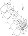
- Figures 1-4 are views of a yarn feeding apparatus according to the invention, in which a group A of yarns Y that unwind from respective spools 10 are fed to a generic downstream textile machine (not shown).
- the spools 10 from which the yarns Y of the group A unwind are arranged mutually side by side with their respective axes horizontal and parallel to each other to form a row F ( Figure 2 ).
- Each of the yarns Y is picked up from the respective spool 10 and sent to the textile machine via a respective motorized yarn winding spool 12 which, in this embodiment, is located near the output end of the spool 10 and has its axis parallel to the axis of the spool 10.
- a control unit CU (shown only schematically in Figure 2 ) adjusts the operation of the motorized yarn winding spools 12 on the basis of the signals received from a tension sensing unit 13 which is adapted to detect the tensions of the yarns Y that belong to the group A.
- the tension sensing unit 13 is arranged downstream of the row F of spools 10 and comprises a series S of clustered tension sensors 14, each of which is associated with a respective yarn Y of the group A.
- Each of the tension sensors 14 is provided with a sensitive element 14a adapted to be slidingly engaged by the yarn Y.
- the tension sensors 14 of the series S are arranged in a row mutually side by side with their respective sensitive elements 14a substantially aligned with each other.
- a first yarn guiding eyelet 16 and a second yarn guiding eyelet 18 guide the yarn Y upstream and downstream of each of the yarn winding spools 12, except for the yarn Y that unwinds from the spool 10 that is closest to the respective tension sensor 14, in relation to which the second yarn guiding eyelet is not present since it is not necessary.
- a third yarn guiding eyelet 20 guides the yarn Y downstream of the respective tension sensor 14.
- the third yarn guiding eyelet 20 is arranged so as to apply to the respective yarn Y that exits from the second yarn guiding eyelet 18 (or, with reference to the yarn Y that unwinds from the spool 10 closest to the respective tension sensor 14, directly from the motorized yarn winding spool 12) a trajectory such as to engage the sensitive element 14a of the respective tension sensor 14.
- a situation of the type shown in Figure 1 occurs in yarn feeding apparatuses for warping machines.
- These apparatuses generally comprise at least one creel, which in a per se known manner may comprise a frame which supports multiple spools distributed over several horizontal rows.
- a single creel may comprise, for example, eight horizontal rows, each containing one hundred spools, for a total of eight hundred spools.
- the tension sensors associated with each horizontal row of spools can be clustered, for example, into four arrays of twenty-five tension sensors, or two arrays of fifty tension sensors, etcetera.
- the motorized yarn winding spools 12, the tension sensors 14 and the yarn guiding eyelets 16, 18, 20 are generally supported by the frame of the creel that supports the spools 10.
- the tension sensing unit 13 comprises a spacer element 22 that is shaped on the basis of the mutual arrangement of the sensitive elements 14a of the tension sensors 14 of the series S and can move between a resting position ( Figures 1 , 1a and 2 ), in which it does not interfere with the trajectory of the yarns Y of the group A, and an operative position ( Figures 3 and 4 ), in which it pushes the yarns Y of the group A away from the respective sensitive elements 14a to perform the zeroing calibration of the tension sensors 14.
- the spacer element 22 is arranged downstream of the series S of tension sensors 14 with respect to the direction of yarn origin.
- the spacer element 22 comprises a body, which in this embodiment consists of a plate 24, which has a contact edge 24a shaped so as to engage all the yarns of the group A when the spacer element 22 is in the operative position.
- the contact edge 24a has a straight profile that is extended parallel to the array.
- the plate 24 is supported so that it can rotate about an axis of rotation R parallel to the contact edge 24a to rotate between the resting position and the operative position.
- the plate 24 has an elongated rectangular profile, the contact edge 24a coinciding with one of the two longer sides of said profile, the axis of rotation R being located proximate to the opposite longer side 24b.
- the plate 24 performs a 180° rotation between the resting position shown in Figures 1 , 1a and 2 , in which it does not interfere with the yarns Y, and the operative position shown in Figures 3 and 4 , in which it moves the yarns Y away from the respective sensors 14.
- the spacer element 22 is motorized.
- the elongated rectangular plate 24 is turned by a motor 26.
- the movement of the spacer element 22 is preferably controlled by the control unit CU.
- control unit CU is programmed to perform an automatic calibration procedure, for example following an operator command or on the basis of a predetermined program in relation to the specific process.
- the control unit CU first moves the spacer element 22 to the operative position, so as to free the tension sensors 14 from any possible force applied by the respective yarns Y, then performs the zeroing calibration of the tension sensors 14, and finally returns the spacer element 22 to the resting position.
- control unit CU is programmed to perform simultaneously the above-described calibration procedure on all arrays of tension sensors.
- the spacer element 22 can generally be supported by the same structure that supports the spools 10, the motorized yarn winding spools 12, the tension sensors 14, and the yarn guiding eyelets 16, 18, 20, for example the frame of a creel.
- the spacer element 22 In operation, during the textile process the spacer element 22 is kept in the resting position. To perform the zero calibration, the spacer element 22 is brought to the operative position, either manually or by means of an automatic or semi-automatic calibration procedure.
- the tension sensing unit according to the invention fully achieves its intended aim and objects, since it allows to perform the zeroing calibration of the tension sensors more reliably and more accurately than known solutions. In fact, during zeroing calibration, all the yarns are moved away from the sensitive elements of the respective tension sensors, so that any contact is prevented and so that they cannot affect the reading taken by the tension sensors.
- the possibility to perform automatically and simultaneously the calibration procedure on all the tension sensing units allows to perform zeroing calibration immediately, regardless of the number of tension sensors involved in the textile process, so as to minimize machine downtime.
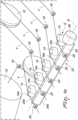
- Figure 5 shows a yarn feeding apparatus which incorporates the tension sensing unit according to another embodiment of the invention.
- the elements that correspond to those of the previous embodiment are designated by the same reference numerals increased by 100 or by the same letter with the addition of a prime.
- the tension sensors 114 of the series S are incorporated in respective yarn feeders YF, each of which is equipped with a motorized yarn winding spool 112 which is operatively arranged upstream of the tension sensor 114.
- the yarn feeders YF are arranged laterally adjacent to each other a short distance apart, with their respective yarn winding spools 112 coaxial to each other.
- Each of the yarn feeders YF is also advantageously provided with an input yarn guiding eyelet 116, which is arranged upstream of the motorized yarn winding spool 112 with respect to the direction from which the yarn Y' arrives, which corresponds to the first yarn guiding eyelet of the previous embodiment, and an output yarn guiding eyelet 120 arranged downstream of the tension sensor 114 with respect to the direction from which the yarn Y' arrives, which corresponds to the third yarn guiding eyelet of the previous embodiment.
- the spacer element 122 comprises an elongated rectangular plate 124, which is arranged between the tension sensors 114 and the output yarn guiding eyelets 120 and is driven by a motor 126.
- the feeders YF and the spacer element 122 are fixed to a generic structure G (shown only schematically in Figure 5 ), for example, the frame of a creel at the output end of said creel.
- the spacer element 122 corresponds to the one described in the previous embodiment.
- Figure 6 shows the spacer element 122 in the resting position
- Figure 7 shows the spacer element 122 in the operative position.
- the yarn feeders 112 are preferably connected to a control unit CU' that can be programmed to manage the rotation of the motorized yarn winding reel 112 on the basis of the signals received from the tension sensor 114, as well as the automatic calibration procedure in a manner that is fully similar to what has been described regarding the previous embodiment.
- the spacer element might be placed upstream of the tension sensors instead of downstream of them.
- the spacer element is a rotating element as in the embodiments described herein, a 180° rotation might not be necessary to move from the resting position to the operative position.
- a rotation of about 90° with respect to the operative position might be sufficient to disengage the spacer element from the yarn and thus bring it to the resting position.
- the longitudinal axis around which the elongated rectangular plate rotates might be located further inward or might even coincide with the centerline axis of the elongated rectangular plate.
- the spacer element 22, 122 is advantageously actuated by a motor controlled by the control unit to which the sensors are connected, in a less automated embodiment the spacer element might be operated manually.
- the rotation of the spacer element 22, 122 might be motorized but actuated by the operator rather than by the control unit, and the unit might be programmed to perform the zeroing calibration either on command from the operator or automatically, for example when none of the tension sensors of the array detect a tension.
- the elongated rectangular plate instead of rotating, might translate between the resting position and the operative position, under manual or motorized control by means of actuation means which are used conventionally in the field.
Landscapes
- Engineering & Computer Science (AREA)
- Quality & Reliability (AREA)
- Tension Adjustment In Filamentary Materials (AREA)
Applications Claiming Priority (1)
| Application Number | Priority Date | Filing Date | Title |
|---|---|---|---|
| IT102023000004974A IT202300004974A1 (it) | 2023-03-16 | 2023-03-16 | Unità di rilevamento della tensione per un gruppo di filati coinvolti in un processo tessile, e apparato di alimentazione di filato comprendente la stessa. |
Publications (1)
| Publication Number | Publication Date |
|---|---|
| EP4431428A1 true EP4431428A1 (fr) | 2024-09-18 |
Family
ID=86732774
Family Applications (1)
| Application Number | Title | Priority Date | Filing Date |
|---|---|---|---|
| EP24161517.8A Pending EP4431428A1 (fr) | 2023-03-16 | 2024-03-05 | Unité de détection de tension pour un ensemble de fils impliqués dans un processus textile, et appareil d'alimentation en fil comprenant l'unité |
Country Status (3)
| Country | Link |
|---|---|
| EP (1) | EP4431428A1 (fr) |
| CN (1) | CN118666096A (fr) |
| IT (1) | IT202300004974A1 (fr) |
Families Citing this family (1)
| Publication number | Priority date | Publication date | Assignee | Title |
|---|---|---|---|---|
| IT202300004974A1 (it) | 2023-03-16 | 2024-09-16 | Lgl Electronics Spa | Unità di rilevamento della tensione per un gruppo di filati coinvolti in un processo tessile, e apparato di alimentazione di filato comprendente la stessa. |
Citations (8)
| Publication number | Priority date | Publication date | Assignee | Title |
|---|---|---|---|---|
| EP0943713A2 (fr) * | 1998-03-14 | 1999-09-22 | Memminger-IRO GmbH | Capteur de tension de fil à ajustement répété |
| EP1129243A2 (fr) * | 1998-11-10 | 2001-09-05 | INVISTA Technologies S.à.r.l. | Appareil d'ensouplage a grande vitesse de fils elastomeres |
| EP1156143A1 (fr) * | 2000-05-17 | 2001-11-21 | Benninger AG | Méthode d'utilisation d'un cantre et cantre pour une machine d'enroulage |
| US6340128B1 (en) * | 1999-08-25 | 2002-01-22 | W. Schlafhorst Ag & Co. | Device for compensating a tensile yarn force sensor |
| DE10130346A1 (de) * | 2001-06-27 | 2003-01-09 | Zsk Stickmasch Gmbh | Fadenspannungssensor als Mehrnadelvariante |
| EP2573027A1 (fr) * | 2011-09-20 | 2013-03-27 | L.G.L. Electronics S.p.A. | Procédé d'étalonnage pour passe-fils à tension contrôlée dans les machines à tisser |
| EP3763651A1 (fr) * | 2019-07-11 | 2021-01-13 | L.G.L. Electronics S.p.A. | Procédé d'alimentation d'une pluralité de fils sous tension contrôlée a une machine textile |
| IT202300004974A1 (it) | 2023-03-16 | 2024-09-16 | Lgl Electronics Spa | Unità di rilevamento della tensione per un gruppo di filati coinvolti in un processo tessile, e apparato di alimentazione di filato comprendente la stessa. |
Family Cites Families (1)
| Publication number | Priority date | Publication date | Assignee | Title |
|---|---|---|---|---|
| IT202200007784A1 (it) | 2022-04-20 | 2023-10-20 | Lgl Electronics Spa | Metodo per l'alimentazione di una pluralità di filati ad un orditoio ed apparato per l'esecuzione di tale metodo |
-
2023
- 2023-03-16 IT IT102023000004974A patent/IT202300004974A1/it unknown
-
2024
- 2024-03-05 EP EP24161517.8A patent/EP4431428A1/fr active Pending
- 2024-03-15 CN CN202410301078.0A patent/CN118666096A/zh active Pending
Patent Citations (8)
| Publication number | Priority date | Publication date | Assignee | Title |
|---|---|---|---|---|
| EP0943713A2 (fr) * | 1998-03-14 | 1999-09-22 | Memminger-IRO GmbH | Capteur de tension de fil à ajustement répété |
| EP1129243A2 (fr) * | 1998-11-10 | 2001-09-05 | INVISTA Technologies S.à.r.l. | Appareil d'ensouplage a grande vitesse de fils elastomeres |
| US6340128B1 (en) * | 1999-08-25 | 2002-01-22 | W. Schlafhorst Ag & Co. | Device for compensating a tensile yarn force sensor |
| EP1156143A1 (fr) * | 2000-05-17 | 2001-11-21 | Benninger AG | Méthode d'utilisation d'un cantre et cantre pour une machine d'enroulage |
| DE10130346A1 (de) * | 2001-06-27 | 2003-01-09 | Zsk Stickmasch Gmbh | Fadenspannungssensor als Mehrnadelvariante |
| EP2573027A1 (fr) * | 2011-09-20 | 2013-03-27 | L.G.L. Electronics S.p.A. | Procédé d'étalonnage pour passe-fils à tension contrôlée dans les machines à tisser |
| EP3763651A1 (fr) * | 2019-07-11 | 2021-01-13 | L.G.L. Electronics S.p.A. | Procédé d'alimentation d'une pluralité de fils sous tension contrôlée a une machine textile |
| IT202300004974A1 (it) | 2023-03-16 | 2024-09-16 | Lgl Electronics Spa | Unità di rilevamento della tensione per un gruppo di filati coinvolti in un processo tessile, e apparato di alimentazione di filato comprendente la stessa. |
Also Published As
| Publication number | Publication date |
|---|---|
| CN118666096A (zh) | 2024-09-20 |
| IT202300004974A1 (it) | 2024-09-16 |
Similar Documents
| Publication | Publication Date | Title |
|---|---|---|
| JP7614752B2 (ja) | ケーブル供給装置、ケーブル処理システム、および、ケーブルをケーブル処理機に供給するための方法 | |
| EP1129243B1 (fr) | Appareil d'ensouplage a grande vitesse de fils elastomeres | |
| CN101223094A (zh) | 用于确保恒定张力纱线喂入纺织机械的双控制回路方法和装置 | |
| EP0933455B1 (fr) | Ourdissoir d'échantillonnage contrôlé électroniquement | |
| EP4431428A1 (fr) | Unité de détection de tension pour un ensemble de fils impliqués dans un processus textile, et appareil d'alimentation en fil comprenant l'unité | |
| JPH0141734B2 (fr) | ||
| CZ283142B6 (cs) | Způsob řízení zanášení útku do prošlupu a tkalcovský stav k provádění tohoto způsobu | |
| CN105383995A (zh) | 生产交叉卷绕筒子的纺织机的工位或相关工位的操作方法 | |
| US3950966A (en) | Demand responsive positive feed device for knitting machine | |
| EP2105397B1 (fr) | Dispositif d'assistance au déroulement pour bobinoir automatique | |
| DE2853662C2 (de) | Schär- oder Zettelanlage | |
| EP3753886B1 (fr) | Dispositif et procédé de commande d'un ballon lors du déroulement d'un fil d'une bobine | |
| KR102464659B1 (ko) | 인터널 로빙 형태의 유리섬유 자동 장력 제어 장치 | |
| JPH06506780A (ja) | ワープ中の経糸の強力特性を求める方法及び装置 | |
| EP3121316B1 (fr) | Machine d'agencement de fils | |
| GB2044816A (en) | Beaming machine | |
| JP2010228852A (ja) | 糸継機構及びそれを用いたサンプル整経機 | |
| DE19940161A1 (de) | Vorrichtung zum Abgleich eines Fadenzugkraftsensors | |
| KR20010049750A (ko) | 크릴의 실결박검출장치 | |
| US4196601A (en) | Endless track rotating thread guide | |
| EP0852217A2 (fr) | Dispositif de contrÔle de la tension | |
| US4903914A (en) | Warping yarn accumulator | |
| CN112209179B (zh) | 将多根纱线在受控张力下馈送到纺织机的方法 | |
| CN100526527C (zh) | 纱线控制装置 | |
| US3263297A (en) | Method and apparatus for winding yarns on a beam |
Legal Events
| Date | Code | Title | Description |
|---|---|---|---|
| PUAI | Public reference made under article 153(3) epc to a published international application that has entered the european phase |
Free format text: ORIGINAL CODE: 0009012 |
|
| STAA | Information on the status of an ep patent application or granted ep patent |
Free format text: STATUS: THE APPLICATION HAS BEEN PUBLISHED |
|
| AK | Designated contracting states |
Kind code of ref document: A1 Designated state(s): AL AT BE BG CH CY CZ DE DK EE ES FI FR GB GR HR HU IE IS IT LI LT LU LV MC ME MK MT NL NO PL PT RO RS SE SI SK SM TR |
|
| STAA | Information on the status of an ep patent application or granted ep patent |
Free format text: STATUS: REQUEST FOR EXAMINATION WAS MADE |
|
| 17P | Request for examination filed |
Effective date: 20240926 |
|
| RBV | Designated contracting states (corrected) |
Designated state(s): AL AT BE BG CH CY CZ DE DK EE ES FI FR GB GR HR HU IE IS IT LI LT LU LV MC ME MK MT NL NO PL PT RO RS SE SI SK SM TR |
|
| GRAP | Despatch of communication of intention to grant a patent |
Free format text: ORIGINAL CODE: EPIDOSNIGR1 |
|
| STAA | Information on the status of an ep patent application or granted ep patent |
Free format text: STATUS: GRANT OF PATENT IS INTENDED |
|
| INTG | Intention to grant announced |
Effective date: 20260330 |