EP2105397B1 - Dispositif d'assistance au déroulement pour bobinoir automatique - Google Patents
Dispositif d'assistance au déroulement pour bobinoir automatique Download PDFInfo
- Publication number
- EP2105397B1 EP2105397B1 EP09154194.6A EP09154194A EP2105397B1 EP 2105397 B1 EP2105397 B1 EP 2105397B1 EP 09154194 A EP09154194 A EP 09154194A EP 2105397 B1 EP2105397 B1 EP 2105397B1
- Authority
- EP
- European Patent Office
- Prior art keywords
- yarn
- bobbin
- elevating
- assisting device
- cylinder
- Prior art date
- Legal status (The legal status is an assumption and is not a legal conclusion. Google has not performed a legal analysis and makes no representation as to the accuracy of the status listed.)
- Active
Links
- 230000003028 elevating effect Effects 0.000 claims description 37
- 230000007246 mechanism Effects 0.000 claims description 37
- 230000008859 change Effects 0.000 claims description 17
- 230000007547 defect Effects 0.000 description 4
- 238000004804 winding Methods 0.000 description 4
- 230000005540 biological transmission Effects 0.000 description 3
- 230000008878 coupling Effects 0.000 description 2
- 238000010168 coupling process Methods 0.000 description 2
- 238000005859 coupling reaction Methods 0.000 description 2
- 238000000034 method Methods 0.000 description 2
- 230000008569 process Effects 0.000 description 2
- 206010020112 Hirsutism Diseases 0.000 description 1
- 230000007423 decrease Effects 0.000 description 1
- 230000000994 depressogenic effect Effects 0.000 description 1
- 238000001514 detection method Methods 0.000 description 1
- 230000003287 optical effect Effects 0.000 description 1
- 238000009987 spinning Methods 0.000 description 1
- 230000007480 spreading Effects 0.000 description 1
Images


Classifications
-
- B—PERFORMING OPERATIONS; TRANSPORTING
- B65—CONVEYING; PACKING; STORING; HANDLING THIN OR FILAMENTARY MATERIAL
- B65H—HANDLING THIN OR FILAMENTARY MATERIAL, e.g. SHEETS, WEBS, CABLES
- B65H49/00—Unwinding or paying-out filamentary material; Supporting, storing or transporting packages from which filamentary material is to be withdrawn or paid-out
- B65H49/02—Methods or apparatus in which packages do not rotate
-
- B—PERFORMING OPERATIONS; TRANSPORTING
- B65—CONVEYING; PACKING; STORING; HANDLING THIN OR FILAMENTARY MATERIAL
- B65H—HANDLING THIN OR FILAMENTARY MATERIAL, e.g. SHEETS, WEBS, CABLES
- B65H57/00—Guides for filamentary materials; Supports therefor
- B65H57/22—Guides for filamentary materials; Supports therefor adapted to prevent excessive ballooning of material
-
- B—PERFORMING OPERATIONS; TRANSPORTING
- B65—CONVEYING; PACKING; STORING; HANDLING THIN OR FILAMENTARY MATERIAL
- B65H—HANDLING THIN OR FILAMENTARY MATERIAL, e.g. SHEETS, WEBS, CABLES
- B65H2701/00—Handled material; Storage means
- B65H2701/30—Handled filamentary material
- B65H2701/31—Textiles threads or artificial strands of filaments
Definitions
- the present invention relates to a yarn unwinding assisting device applied to an automatic winder.
- the yarn unwinding assisting device unwinds and guides a yarn supplying from a bobbin (spinning bobbin) to allow a winder unit to smoothly carry out a yarn rewinding process.
- the yarn unwinding device in the Unexamined Japanese Patent Application Publication (Tokkai-Hei) No. 10-29765 is well known.
- the yarn unwinding device is composed of a fixed cylinder fixed to a bottom surface of a guide plate, a movable cylinder externally fitted around the fixed cylinder which is displaceably elevated and lowered, an operation cylinder that elevates and lowers the movable cylinder via a slide block, and the like.
- the movable cylinder, and a pair of a front support arm and a rear support arm are fixed to the slide block.
- a sensor sensing a chase portion of a bobbin and a posture correcting arm are arranged on each of the opposite surfaces of the two arms.
- the chase portion of the bobbin moves gradually downward as a yarn is unwound and supplied from the bobbin.
- the sensors sense the downward movement of the chase portion to drive the operation cylinder to operatively lower the slide block by an amount corresponding to the amount by which the chase portion lowers.
- the movable cylinder and the sensor arms move downward in conjunction with a change in the position of the chase portion. This maintains a vertical positional relationship between the chase portion and the movable cylinder constant.
- the movable cylinder prevents a balloon formed by the yarn unwound from the chase portion from spreading excessively. This allows a suitable tension to be applied to the yarn being unwound and inhibits generation of hairiness.
- a yarn unwinding assisting device allows, instead of the above-described operation cylinder, an elevating and lowering mechanism that uses a stepping motor as a driving source to individually elevate and lower the fixed and movable cylinders.
- An elevating and lower mechanism is known from the Unexamined Japanese Patent Application Publication (Tokkai-Hei) No. 8-198520 . According to the Unexamined Japanese Patent Application Publication (Tokkai-Hei) No.
- the elevating and lowering mechanism is composed of an elevating and lowering guide, a slide block, a rack located parallel to the elevating and lowering guide, a stepping motor incorporated in the slide block, a rack fixed to an output shaft of the stepping motor, and the like.
- a support arm is fixed to the slide block, and the movable cylinder is fixed to a tip of the arm.
- a distance sensor is provided on the support arm to sense the chase portion of the bobbin.
- a rotation number detecting sensor is provided which detects the amount by which the yarn has been unwound from the bobbin, based on the rotation number of a traverse drum. Rotational driving of the rack displaceably elevates and lowers the slide block.
- the movable cylinder can be lowered in conjunction with a change in the position of the bobbin chase portion.
- initial positions of the fixed cylinder, the movable cylinder, and the like need to be adjustably changed every time the vertical size of the bobbin is changed in association with a lot change.
- This setup changing operation needs to be manually performed.
- a large number of winder units are arranged in a line.
- much time and effort is unavoidably required to change the setup of the group of winder units.
- the manual adjustable change is likely to result in a variation in adjustment results.
- An object of the present invention is to allow the initial position or operating position of the yarn unwinding assisting device to be automatically changed depending on a change in the vertical size of the bobbin.
- the object of the present invention is to provide a yarn unwinding assisting device for an automatic winder which allows the setup of the automatic winder to be quickly and accurately changed in association with a lot change.
- a yarn unwinding assisting device provided in a winder unit comprises a fixed cylinder held in a fixed condition to assist unwinding of a yarn from a bobbin, and a movable cylinder moving in conjunction with the unwinding of the yarn from the bobbin, while assisting the unwinding of the yarn from the bobbin.
- the yarn unwinding assisting device is characterized in that the fixed cylinder is elevated and lowered by a first elevating and lowering mechanism having a driving source, so as to change an initial position of the fixed cylinder, and the movable cylinder is elevated and lowered by a second elevating and lowering mechanism having a driving source.
- the driving source of the first elevating and lowering mechanism and the driving source of the second elevating and lowering mechanism each comprise a stepping motor.
- the yarn unwinding assisting device further comprises a control circuit controlling operating states of both the first and second elevating and lowering mechanisms. Based on bobbin data pre-input to the control circuit, this control mechanism allows the control circuit to control the operating states of both elevating and lowering mechanisms to automatically set initial positions and operating positions of the fixed cylinder and the movable cylinder.
- An automatic winder includes a plurality of winder units arranged therein and each having the above-described yarn unwinding assisting device with the control circuit.
- the automatic winder comprises a frame control device controlling the control circuit.
- the frame control device can control a plurality of the control circuits at a time.
- the yarn unwinding assisting device comprises the fixed cylinder held in the fixed condition to assist unwinding of the yarn from the bobbin, and the movable cylinder moving in conjunction with the unwinding of the yarn from the bobbin, while assisting the unwinding of the yarn from the bobbin.
- the fixed cylinder is elevated and lowered by the first elevating and lowering mechanism having the driving source.
- the movable cylinder is elevated and lowered by the second elevating and lowering mechanism having the driving source.
- the present invention allows the setup of a group of winder units to be concurrently and quickly changed. Since the setup change can be achieved in a very short time, the operating rate of the automatic winder can be improved. Furthermore, the fixed and movable cylinders can be accurately held at the initial positions or the operating positions.
- the fixed cylinder and the movable cylinder can be displaceably elevated and lowered accurately without delay by the first and second elevating and lowering mechanisms.
- the current positions of the fixed cylinder and the movable cylinder can be determined based on detection signals output by position detectors on the stepping motors.
- the control circuit can set the initial positions and operating positions of the fixed cylinder and the movable cylinder based on the pre-input bobbin data and the sensing signals from the position detectors on the stepping motors. Moreover, according to the setting contents, the control circuit can control the operating states of both elevating and lowering mechanisms to elevate and lower the fixed cylinder and the movable cylinder to the initial positions and the operating positions thereof.
- the automatic winder according to the present invention is composed of the plurality of winder units arranged therein and each having the above-described yarn unwinding assisting device with the control circuit. Furthermore, the automatic winder comprises the frame control device controlling the individual control circuits. Thus, the automatic winder according to the present invention allows the frame control device to control the individual control circuits at a time. The initial positions and operating positions of the fixed and movable cylinders can be concurrently and automatically changed in the group of winder units.
- the present automatic winder allows the setup of the group of winder units to be quickly changed, thus offering an improved operating rate.
- FIGs 1 to 5 show an embodiment of an automatic winder according to the present invention.
- the automatic winder is composed of a group of winding units arranged in a line; one of the winding units is shown in Figure 2 .
- the winder unit has an elongate machine body 2 located so as to face a conveying path for a bobbin 1.
- a yarn unwinding assisting device, a tension device 3, a yarn splicing device 4, a slab catcher 5, and the like are arranged in the front of the machine body 2 in this order from the bottom to top of the machine body 2.
- a traverse drum 6, a guide plate 7, a cradle 8, and the like are arranged in an upper front portion of the machine body 2; the traverse drum 6 traverses a yarn Y in a given width range, the guide plate 7 is arranged so as to face to a traverse area of the traverse drum 6, and the cradle 8 rotatably supports a package P.
- a relay pipe 9 and a suction mouth 10 which suck, catch, and pass the cut yarn to the yarn splicing device 4 are provided in the middle of the equipment row so as to be swingable in a vertical direction.
- the yarn Y unwound from the bobbin 1 is checked for a yarn defect while passing through the equipments 3 to 5. When a yarn defect is found, the yarn Y is cut by a cutter provide in the slab catcher 5 and a cutter provided in the yarn splicing device 4. The defect portion is sucked and removed.
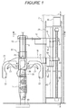
- the yarn unwinding assisting device is composed of, for example, a fixed cylinder 15 fixed to a first holder 14 above the bobbin 1, a movable cylinder 17 fixed to a second holder 16, and a first elevating and lowering mechanism 18 and a second elevating and lowering mechanism 19 which individually elevate and lower the cylinders 15, 17, respectively.
- the fixed cylinder 15 and the movable cylinder 17 are concentrically arranged such that the movable cylinder 17 is located outside the fixed cylinder 15 so as to overlappingly surround the fixed cylinder 15.
- Support arms 21 are fixed to the second holder 16 so as to lie opposite each other across a chase portion 20 of the bobbin 1.
- a sensor 22 and one of posture correcting arm 23 are arranged on each of the opposite surfaces of the support arms 21; the sensor 22 senses the chase portion 20, and the posture correcting arms 23 sandwichingly hold an upper part of a core tube of the bobbin 1 when required.
- the first and second elevating and lowering mechanisms 18, 19 are arranged adjacent to each other in a lateral direction.
- the fixed cylinder 15 is composed of a cylinder with an open upper end and an open lower end, and a yarn guide 25 is provided in a central portion of an opening in a bottom surface of the fixed cylinder 15.
- the movable cylinder 16 is composed of a cylinder larger than the fixed cylinder 15. An upper end of the movable cylinder is open, and an introduction port 26 tapered such that the diameter thereof increases toward the bottom of the port is formed at a lower end of the movable cylinder 16.
- the first elevating and lowering mechanism 18 is composed of a lateral pair of guide shafts (guide members) 30 that upper ends of the guide shafts 30 are fixed to the frame 29, a slider 31 guided by both guide shafts 30 so as to elevate and lower freely, and a driving structure that elevates and lowers the slider 31 along the guide shafts 30.
- a lower end of each of the guide shafts 30 is fixed to a bracket 32 projecting from a vertically middle part of the frame 29.
- the first holder 14 is fixed to a front surface of the slider 31.
- the driving structure is composed of a stepping motor (driving source) 35 fixed to an upper end of the frame 29, a feed screw shaft 36 rotationally driven by the stepping motor 35, and a female threaded member 37 elevated and lowered by the feed screw shaft 36.
- An upper end of the feed screw shaft 36, located parallel to the guide shafts 30, is coupled to the stepping motor 35 via a coupling, and a lower end of the feed screw shaft 36 is rotatably supported by the bracket 32.
- the female threaded member 37 is fixed to a rear surface of the slider 31, described above.
- the fixed cylinder 15 can be elevated or lowered.
- the female threaded member 37 can be elevated or lowered only when the feed screw shaft 36 is rotationally driven by the stepping motor 35.
- the female threaded member 37 can self-hold a position to which the female threaded member 37 has been elevated or lowered.
- the second elevating and lowering mechanism 19 is composed of a lateral pair of guide shafts (guide members) 40 that an upper end and a lower end both are fixed to the frame 29, a slider 41 guided by both guide shafts 40 so as to elevate and lower freely, and a driving structure that elevates and lowers the slider 41 along the guide shafts 40.
- the second holder 16 is fixed to a front surface of the slider 41.
- the driving structure is composed of a stepping motor (driving source) 45 fixed to the upper end of the frame 29, a feed screw shaft 46 rotationally driven by the stepping motor 45, and a female threaded member 47 elevated and lowered by the feed screw shaft 46.
- An upper end of the feed screw shaft 46 located parallel to the guide shafts 40, is coupled to the stepping motor 45 via a coupling.
- a lower end of the feed screw shaft 46 is rotatably supported by the frame 29.
- the female threaded member 47 is fixed to a rear surface of the slider 41, described above.
- the stepping motor 45 is rotationally driven forward or backward, the feed screw shaft 46 rotates concurrently to allow the female threaded member 47 to be displaceably elevated or lowered.
- the movable cylinder 17 can be elevated or lowered.
- the female threaded member 47 has a function of self-holding the position to which the female threaded member 47 has been elevated or lowered.
- the sensor 22 is composed of an optical sensor including a floodlighting portion and a light receiving portion.
- the sensor 22 senses a yarn layer on the chase portion 20 depending on whether or not sensing light emitted by the floodlighting portion is received by the light receiving portion. Furthermore, the sensor 22 can sense the height of the chase portion 20 to determine whether the bobbin 1 is a full bobbin in a fully wound condition, a half bobbin from which a part of the yarn layer has been unwound by the automatic winder, or a smaller bobbin with a small amount of remaining yarn.
- the paired posture correcting arms 23 swing downward to hold an upper end of the core tube so that the upper end is sandwiched between the posture correcting arms 23.
- the bobbin 1 is thus positioned.
- the positioning aligns a central axis of the bobbin 1 with a cylinder central axis of the fixed cylinder 15 and the movable cylinder 17.
- the posture correcting arms 23 return swingably to a position shown by a solid line in Figure 1 , where the posture correcting arms 23 stand by.
- reference numeral 50 is a control circuit that controls operating states of the first and second elevating and lowering mechanisms 18, 19.
- a sensing signal from the light receiving portion of the sensor 22 is output to the control circuit 50.
- a position signal from an encoder (position detector) on the stepping motor 45 is output to the control circuit 50.
- the automatic winder includes a frame control device that controls the control circuit 50 for the group of winder units. The frame control device can control the individual control circuits 50 at a time.
- the fixed cylinder 15 is operatively lowered by the first elevating and lowering mechanism 18 from the initial position to an operating position thereof located at a predetermined height.
- the movable cylinder 17 is operatively lowered by the second elevating and lowering mechanism 19 from the initial position to an operating position thereof located at a predetermined height.
- the operating position of the fixed cylinder 15 corresponds to the vertical size of the bobbin 1. As shown in Figure 1 , the opening at the lower end of the fixed cylinder 15 is positioned at a distance of 10 mm from the upper end of the core tube of the bobbin 1. Similarly, the operating position of the movable cylinder 17 corresponds to the height position of the chase portion 20 of the bobbin 1. At the operating position, the opening at the lower end of the movable cylinder 17 faces to the top of the chase portion 20.
- a winding core of the package P is rotationally driven to start winding back the yarn Y.
- the fixed cylinder 15 and the movable cylinder 17 regulate the spread of a balloon formed by the yarn Y unwound from the bobbin 1 to apply an appropriate tension to the wound-back yarn Y.
- the height of the chase portion 20 decreases gradually. Then, light to be sensed by the sensor 22 which has been blocked by a larger-diameter end of the chase portion 20 is received by the light receiving portion, which then outputs a light reception signal to the control circuit 50. Upon receiving the light reception signal, the control circuit 50 transmits an operation instruction signal to the stepping motor 45 of the second elevating and lowering mechanism 19, and the slider 41 is thus lowered via the female threaded member 47. The stepping motor 45 is stopped when the light sensed by the sensor 22 is blocked by the larger-diameter end of the chase portion 20 again.
- the movable cylinder 17 can be lowered to a new operating position in conjunction with a change in the position of the chase portion 20.
- the lowering operation of the movable cylinder 17 in conjunction with the change in the position of the chase portion 20 is repeated until all of the yarn Y wound around the bobbin 1 is unwound and supplied.
- the positioning by the posture correcting arms 23, the splicing by the yarn splicing device 4, and other required operations are also performed as described above.
- the position of the chase portion 20 of the half bobbin is lower than that of the bobbin 1 in the fully wound condition.
- the movable cylinder 17 is operatively lowered at one stroke from the initial position to an operating position thereof where the light to be sensed by the sensor 22 is blocked by the larger-diameter end of the chase portion 20.
- the series of operations are similarly performed.
- the initial position of the yarn unwinding assisting device is changed.
- bobbin data is pre-input to the control circuit 50, and for example, an execution button is depressed for a turn-on operation. Then, the initial positions of the fixed cylinder 15 and the movable cylinder 17 are automatically determined by the control circuit 50.
- the stepping motors 35, 45 are driven to elevate or lower the fixed cylinder 15 and the movable cylinder 17 to place the fixed cylinder 15 and the movable cylinder 17 at the initial positions thereof corresponding to the bobbin 1 from the new lot.
- the control circuit 50 recognizes the home positions of the first and second elevating and lowering mechanisms 18, 19.
- the control circuit 50 can further determine the current positions of the fixed cylinder 15 and the movable cylinder 17 based on the number of steps detected by the encoders (position detectors) of the stepping motors 35, 45.
- the control circuit 50 can determine the initial positions and operating positions of the fixed cylinder 15 and the movable cylinder 17 in association with the bobbin 1 with the different vertical size, based on the pre-input bobbin data.
- the stepping motors 35, 45 can be driven so as to move the fixed cylinder 15 and the movable cylinder 17 from the initial positions determined from the current positions.
- the automatic winder according to the present invention can automatically change the positions of the fixed cylinder 15 and the movable cylinder 17. Consequently, compared to the conventional apparatuses requiring manual setup changes, the present automatic winder can concurrently and quickly change the setup of the group of winder units. Furthermore, the setup can be changed in a very short time, thus improving the operating rate of the automatic winder.
- transmission elements of the driving structure are the feed screw shafts 36, 46 and the female threaded members 37, 47.
- the transmission elements of the driving structure may be a vertical pair of timing pulleys and a timing belt, with the sliders 31, 41 fixed to a portion of the timing belt which follows a straight portion.
- the transmission elements of the driving structure may be a rack guided and supported so as to be slidable in the vertical direction and a pinion driving the rack in the vertical direction.
- the fixed cylinder 15 is driven by the first elevating and lowering mechanism so as to adjust the initial position of the fixed cylinder 15.
- the fixed cylinder 15 may be driven by the first elevating and lowering mechanism according to the tension of the yarn Y.
Landscapes
- Replacing, Conveying, And Pick-Finding For Filamentary Materials (AREA)
- Guides For Winding Or Rewinding, Or Guides For Filamentary Materials (AREA)
Claims (4)
- Dispositif d'aide au dévidage de fil prévu dans une unité de bobinage, le dispositif d'aide au dévidage de fil comprenant un cylindre fixe (15) maintenu dans un état fixe, pour aider au dévidage du fil d'une bobine, et un cylindre mobile (16) se déplaçant conjointement au dévidage du fil de la bobine, tout en aidant au dévidage du fil de la bobine, et en cela le dispositif d'aide au dévidage de fil est caractérisé en ce que le cylindre fixe (15) est monté et descendu au moyen d'un premier mécanisme de montée et de descente (18), doté d'une source d'entraînement, de façon à modifier la position initiale du cylindre fixe (15), et un cylindre mobile (16) est monté et descendu au moyen d'un deuxième mécanisme de montée et de descente (19) doté d'une source d'entraînement.
- Dispositif d'aide au dévidage de fil selon la revendication 1, caractérisé en ce que la source d'entraînement du premier mécanisme de montée et de descente (18) et la source d'entraînement du deuxième mécanisme de montée et de descente (19) comprennent chacune un moteur pas-à-pas (35, 45).
- Dispositif d'aide au dévidage de fil selon la revendication 2, caractérisé en ce que le dispositif d'aide au dévidage de fil comprend également un circuit de commande (50) contrôlant les états de fonctionnement de, à la fois, le premier et le deuxième mécanisme de montée et de descente, et en se basant sur les entrées préalables des données de la bobine dans le circuit de commande (50), le circuit de commande contrôlant les états de fonctionnement des deux mécanismes de montée et de descente, pour permettre de régler automatiquement la position initiale et la position de fonctionnement du cylindre fixe (15) et du cylindre mobile (16).
- Bobinoir automatique incluant une pluralité d'unités de bobinage disposées à l'intérieur de celui-ci , chacune étant dotée du dispositif d'aide au dévidage selon la revendication 3, le bobinoir automatique étant caractérisé en ce qu'il comprend un dispositif de commande de cadre contrôlant le circuit de commande (50), et par le fait que le dispositif de commande du cadre peut contrôler une pluralité de circuits de commande (50) simultanément.
Applications Claiming Priority (1)
| Application Number | Priority Date | Filing Date | Title |
|---|---|---|---|
| JP2008088647A JP2009242028A (ja) | 2008-03-28 | 2008-03-28 | 自動ワインダーの糸解舒補助装置、および自動ワインダー |
Publications (3)
| Publication Number | Publication Date |
|---|---|
| EP2105397A2 EP2105397A2 (fr) | 2009-09-30 |
| EP2105397A3 EP2105397A3 (fr) | 2012-08-08 |
| EP2105397B1 true EP2105397B1 (fr) | 2016-11-16 |
Family
ID=40785665
Family Applications (1)
| Application Number | Title | Priority Date | Filing Date |
|---|---|---|---|
| EP09154194.6A Active EP2105397B1 (fr) | 2008-03-28 | 2009-03-03 | Dispositif d'assistance au déroulement pour bobinoir automatique |
Country Status (3)
| Country | Link |
|---|---|
| EP (1) | EP2105397B1 (fr) |
| JP (1) | JP2009242028A (fr) |
| CN (1) | CN101544324B (fr) |
Families Citing this family (7)
| Publication number | Priority date | Publication date | Assignee | Title |
|---|---|---|---|---|
| JP2011105460A (ja) * | 2009-11-18 | 2011-06-02 | Murata Machinery Ltd | 糸巻取機 |
| JP2012197147A (ja) * | 2011-03-22 | 2012-10-18 | Murata Machinery Ltd | 巻取ユニット、自動ワインダ、及び給糸ボビンの位置合わせ方法 |
| JP2013035664A (ja) * | 2011-08-09 | 2013-02-21 | Murata Machinery Ltd | 糸巻取装置及び糸解舒方法 |
| JP2013067459A (ja) | 2011-09-21 | 2013-04-18 | Murata Machinery Ltd | 自動ワインダーの糸解舒補助装置 |
| CN110871977B (zh) * | 2018-09-03 | 2024-07-26 | 天津工业大学 | 一种用于纱库式自动络筒机的管纱取放装置 |
| JP2020172362A (ja) * | 2019-04-10 | 2020-10-22 | 村田機械株式会社 | ガイド筒 |
| IT201900009687A1 (it) * | 2019-06-21 | 2020-12-21 | Savio Macch Tessili Spa | Dispositivo e metodo per il controllo di un balloon durante la dipanatura di un filato da una spola |
Citations (1)
| Publication number | Priority date | Publication date | Assignee | Title |
|---|---|---|---|---|
| JPH1029765A (ja) * | 1996-07-10 | 1998-02-03 | Murata Mach Ltd | 解舒装置 |
Family Cites Families (4)
| Publication number | Priority date | Publication date | Assignee | Title |
|---|---|---|---|---|
| DE3917406A1 (de) * | 1989-05-29 | 1990-12-06 | Zinser Textilmaschinen Gmbh | Antriebsvorrichtung fuer mindestens eine ringbank und fuer baenke von balloneinengungsringen und/oder fadenfuehrern einer ringspinn- oder zwirnmaschine |
| JPH08198520A (ja) | 1995-01-23 | 1996-08-06 | Murata Mach Ltd | ワインダの解舒補助装置 |
| DE60120544T2 (de) * | 2000-04-12 | 2007-06-06 | Murata Kikai K.K. | Spulautomat mit einer Vorrichtung zur Unterdrückung der Garnhaarigkeit |
| DE102005036704A1 (de) * | 2005-08-04 | 2007-02-15 | Saurer Gmbh & Co. Kg | Spulstelle einer Kreuzspulen herstellenden Textilmaschine |
-
2008
- 2008-03-28 JP JP2008088647A patent/JP2009242028A/ja active Pending
-
2009
- 2009-02-18 CN CN2009100064500A patent/CN101544324B/zh active Active
- 2009-03-03 EP EP09154194.6A patent/EP2105397B1/fr active Active
Patent Citations (1)
| Publication number | Priority date | Publication date | Assignee | Title |
|---|---|---|---|---|
| JPH1029765A (ja) * | 1996-07-10 | 1998-02-03 | Murata Mach Ltd | 解舒装置 |
Also Published As
| Publication number | Publication date |
|---|---|
| EP2105397A3 (fr) | 2012-08-08 |
| EP2105397A2 (fr) | 2009-09-30 |
| CN101544324A (zh) | 2009-09-30 |
| CN101544324B (zh) | 2012-10-03 |
| JP2009242028A (ja) | 2009-10-22 |
Similar Documents
| Publication | Publication Date | Title |
|---|---|---|
| EP2105397B1 (fr) | Dispositif d'assistance au déroulement pour bobinoir automatique | |
| EP2671830B1 (fr) | Machine textile, procédé permettant de déterminer la position d'attente d'élément entraîné d'unité d'enroulement et unité d'enroulement | |
| EP2502863B1 (fr) | Unité d'enroulement, enrouleur automatique et procédé d'alignement de bobine d'alimentation de fil | |
| EP2105401A2 (fr) | Appareil d'extraction d'extremité de fil | |
| EP2388226B1 (fr) | Unité d'enroulement et machine d'enroulement de fils équipée de celle-ci | |
| EP2690045B1 (fr) | Dispositif de surveillance de fil, unité de bobinage de fil et machine de bobinage de fil | |
| JP6080428B2 (ja) | 綾巻きパッケージを製造する繊維機械のための糸スプライシング装置 | |
| EP2388225B1 (fr) | Unité d'enroulement | |
| EP2072440B1 (fr) | Dispositif d'assistance de déroulement et méthode pour faire fonctionner un dispositif d'assistance de déroulement | |
| EP2502865B1 (fr) | Dévidoir | |
| EP2738129A2 (fr) | Machine de bobinage de fil et machine textile la comprenant | |
| EP2388223B1 (fr) | Unité d'enroulement et machine d'enroulement de fils équipée de celle-ci | |
| CN211895446U (zh) | 张力施加线材的供给装置 | |
| JP2015182868A (ja) | ボビンストッカ及び糸巻取機 | |
| EP2749516B1 (fr) | Dispositif d'épissage de fil et machine d'enroulement de fils | |
| EP2669229B1 (fr) | Dispositif de décharge d'une bobine et machine de bobinage de fil | |
| EP2738128A2 (fr) | Machine de renvideur de fil | |
| EP2567921B1 (fr) | Unité de renvidage | |
| CN111132918B (zh) | 纱线卷取机 | |
| JP2018027857A (ja) | 綾巻きパッケージを製造する繊維機械の作業ユニット | |
| JP2014101189A (ja) | 繊維機械 | |
| EP2573015B1 (fr) | Dispositif d'assistance de déroulement de fil pour enrouleur automatique | |
| EP4197949B1 (fr) | Machine de bobinage de fil | |
| JP2021167240A (ja) | シールテープ巻き付け装置 | |
| HK1164821A1 (en) | Device for feeding a quasi-endless material web |
Legal Events
| Date | Code | Title | Description |
|---|---|---|---|
| PUAI | Public reference made under article 153(3) epc to a published international application that has entered the european phase |
Free format text: ORIGINAL CODE: 0009012 |
|
| AK | Designated contracting states |
Kind code of ref document: A2 Designated state(s): AT BE BG CH CY CZ DE DK EE ES FI FR GB GR HR HU IE IS IT LI LT LU LV MC MK MT NL NO PL PT RO SE SI SK TR |
|
| AX | Request for extension of the european patent |
Extension state: AL BA RS |
|
| PUAL | Search report despatched |
Free format text: ORIGINAL CODE: 0009013 |
|
| AK | Designated contracting states |
Kind code of ref document: A3 Designated state(s): AT BE BG CH CY CZ DE DK EE ES FI FR GB GR HR HU IE IS IT LI LT LU LV MC MK MT NL NO PL PT RO SE SI SK TR |
|
| AX | Request for extension of the european patent |
Extension state: AL BA RS |
|
| RIC1 | Information provided on ipc code assigned before grant |
Ipc: B65H 49/02 20060101AFI20120629BHEP Ipc: B65H 57/22 20060101ALI20120629BHEP |
|
| 17P | Request for examination filed |
Effective date: 20121114 |
|
| AKX | Designation fees paid |
Designated state(s): DE IT |
|
| GRAP | Despatch of communication of intention to grant a patent |
Free format text: ORIGINAL CODE: EPIDOSNIGR1 |
|
| INTG | Intention to grant announced |
Effective date: 20160606 |
|
| GRAS | Grant fee paid |
Free format text: ORIGINAL CODE: EPIDOSNIGR3 |
|
| GRAA | (expected) grant |
Free format text: ORIGINAL CODE: 0009210 |
|
| AK | Designated contracting states |
Kind code of ref document: B1 Designated state(s): DE IT |
|
| REG | Reference to a national code |
Ref country code: DE Ref legal event code: R096 Ref document number: 602009042387 Country of ref document: DE |
|
| REG | Reference to a national code |
Ref country code: DE Ref legal event code: R097 Ref document number: 602009042387 Country of ref document: DE |
|
| PLBE | No opposition filed within time limit |
Free format text: ORIGINAL CODE: 0009261 |
|
| STAA | Information on the status of an ep patent application or granted ep patent |
Free format text: STATUS: NO OPPOSITION FILED WITHIN TIME LIMIT |
|
| 26N | No opposition filed |
Effective date: 20170817 |
|
| PGFP | Annual fee paid to national office [announced via postgrant information from national office to epo] |
Ref country code: DE Payment date: 20250218 Year of fee payment: 17 |
|
| PGFP | Annual fee paid to national office [announced via postgrant information from national office to epo] |
Ref country code: IT Payment date: 20250218 Year of fee payment: 17 |