EP4432430A1 - Verfahren zur herstellung eines beutelgehäuses für eine sekundärbatterie - Google Patents
Verfahren zur herstellung eines beutelgehäuses für eine sekundärbatterie Download PDFInfo
- Publication number
- EP4432430A1 EP4432430A1 EP22911994.6A EP22911994A EP4432430A1 EP 4432430 A1 EP4432430 A1 EP 4432430A1 EP 22911994 A EP22911994 A EP 22911994A EP 4432430 A1 EP4432430 A1 EP 4432430A1
- Authority
- EP
- European Patent Office
- Prior art keywords
- secondary battery
- sealant layer
- layer
- pouch
- pouch exterior
- Prior art date
- Legal status (The legal status is an assumption and is not a legal conclusion. Google has not performed a legal analysis and makes no representation as to the accuracy of the status listed.)
- Pending
Links
Images


Classifications
-
- H—ELECTRICITY
- H01—ELECTRIC ELEMENTS
- H01M—PROCESSES OR MEANS, e.g. BATTERIES, FOR THE DIRECT CONVERSION OF CHEMICAL ENERGY INTO ELECTRICAL ENERGY
- H01M50/00—Constructional details or processes of manufacture of the non-active parts of electrochemical cells other than fuel cells, e.g. hybrid cells
- H01M50/10—Primary casings; Jackets or wrappings
- H01M50/102—Primary casings; Jackets or wrappings characterised by their shape or physical structure
- H01M50/105—Pouches or flexible bags
-
- H—ELECTRICITY
- H01—ELECTRIC ELEMENTS
- H01M—PROCESSES OR MEANS, e.g. BATTERIES, FOR THE DIRECT CONVERSION OF CHEMICAL ENERGY INTO ELECTRICAL ENERGY
- H01M50/00—Constructional details or processes of manufacture of the non-active parts of electrochemical cells other than fuel cells, e.g. hybrid cells
- H01M50/10—Primary casings; Jackets or wrappings
- H01M50/116—Primary casings; Jackets or wrappings characterised by the material
- H01M50/117—Inorganic material
- H01M50/119—Metals
-
- H—ELECTRICITY
- H01—ELECTRIC ELEMENTS
- H01M—PROCESSES OR MEANS, e.g. BATTERIES, FOR THE DIRECT CONVERSION OF CHEMICAL ENERGY INTO ELECTRICAL ENERGY
- H01M50/00—Constructional details or processes of manufacture of the non-active parts of electrochemical cells other than fuel cells, e.g. hybrid cells
- H01M50/10—Primary casings; Jackets or wrappings
- H01M50/116—Primary casings; Jackets or wrappings characterised by the material
- H01M50/121—Organic material
-
- H—ELECTRICITY
- H01—ELECTRIC ELEMENTS
- H01M—PROCESSES OR MEANS, e.g. BATTERIES, FOR THE DIRECT CONVERSION OF CHEMICAL ENERGY INTO ELECTRICAL ENERGY
- H01M50/00—Constructional details or processes of manufacture of the non-active parts of electrochemical cells other than fuel cells, e.g. hybrid cells
- H01M50/10—Primary casings; Jackets or wrappings
- H01M50/116—Primary casings; Jackets or wrappings characterised by the material
- H01M50/124—Primary casings; Jackets or wrappings characterised by the material having a layered structure
- H01M50/126—Primary casings; Jackets or wrappings characterised by the material having a layered structure comprising three or more layers
- H01M50/129—Primary casings; Jackets or wrappings characterised by the material having a layered structure comprising three or more layers with two or more layers of only organic material
-
- Y—GENERAL TAGGING OF NEW TECHNOLOGICAL DEVELOPMENTS; GENERAL TAGGING OF CROSS-SECTIONAL TECHNOLOGIES SPANNING OVER SEVERAL SECTIONS OF THE IPC; TECHNICAL SUBJECTS COVERED BY FORMER USPC CROSS-REFERENCE ART COLLECTIONS [XRACs] AND DIGESTS
- Y02—TECHNOLOGIES OR APPLICATIONS FOR MITIGATION OR ADAPTATION AGAINST CLIMATE CHANGE
- Y02E—REDUCTION OF GREENHOUSE GAS [GHG] EMISSIONS, RELATED TO ENERGY GENERATION, TRANSMISSION OR DISTRIBUTION
- Y02E60/00—Enabling technologies; Technologies with a potential or indirect contribution to GHG emissions mitigation
- Y02E60/10—Energy storage using batteries
Definitions
- the present invention relates to a method for manufacturing a pouch case for a secondary battery, and more specifically, a method for manufacturing a pouch case for a secondary battery, the method including reducing cracks of a sealant layer of a pouch exterior for a secondary battery.
- a pouch exterior for a secondary battery is pressed to a specific depth using a punch and molded.
- the shape of the pouch exterior for a secondary battery is deformed by a pressure caused by the punch and a cup part is formed.
- a pinhole or a crack may be formed on a barrier layer of the molded pouch exterior for a secondary battery, or wrinkles may be formed thereon, and a whitening phenomenon may occur in a sealant layer.
- the whitening phenomenon of the sealant layer is known as a phenomenon in which the surface of the sealant layer looks white due to fine cracks and microvoids generated by tensile stress when the pouch exterior for a secondary battery is molded.
- An aspect of the present invention provides a method for manufacturing a pouch case for a secondary battery capable of reducing the whitening of a sealant layer.
- a method for manufacturing a pouch case for a secondary battery including the steps of: (S1) preparing a pouch exterior for a secondary battery including a structure in which a substrate layer, a barrier layer, and a sealant layer are sequentially stacked; (S2) molding the pouch exterior for a secondary battery to form a cup part; and (S3) reducing cracks of the sealant layer of the pouch exterior for a secondary battery.
- the sealant layer of the molded pouch exterior for a secondary battery is heated, thereby reducing cracks and whitening of the sealant layer, and thus it is possible to manufacture a pouch case for a secondary battery having improved durability and stability.
- the method for manufacturing a pouch case for a secondary battery according to the present invention includes the following steps (S1) to (S3):
- the inventors of the present invention have found that after forming a cup part by molding a pouch exterior for a secondary battery, the sealant layer of the pouch exterior for a secondary battery is heated, thereby reducing the cracks and the whitening phenomenon of the sealant layer, and have completed the present invention.
- the sealant layer of the pouch exterior for a secondary battery when the sealant layer of the pouch exterior for a secondary battery is heated after the cup part is formed by molding the pouch exterior for a secondary battery, materials contained in the sealant layer may be expanded and thus defects such as cracks or voids present inside the sealant layer may be filled. Accordingly, the durability of the sealant layer may be significantly improved, and the pouch case for a secondary battery including the sealant layer may also be significantly improved.
- a pouch exterior for a secondary battery including a structure in which a substrate layer, a barrier layer, and a sealant layer are sequentially stacked is prepared (S1).
- FIG. 1 schematically illustrates a cross-section of a pouch exterior for a secondary battery.
- a pouch exterior 100 for a secondary battery includes a structure in which a substrate layer 110, a barrier layer 120, and a sealant layer 130 are sequentially stacked.
- the substrate layer 110 may be disposed at the outermost side of the pouch case for a secondary battery, and serve to protect the barrier layer 120, the sealant layer 130, and an electrode assembly (not shown) and an electrolyte (not shown) disposed inside the pouch case for a secondary battery from external materials, air, moisture, or the like.
- the substrate layer 110 may include at least one selected from the group consisting of polyethylene, polypropylene, polyethylene terephthalate, and nylon.
- the substrate layer 110 includes the material, and thus can effectively protect the barrier layer 120, the sealant layer 130, the electrode assembly, and the electrolyte from external materials, air, moisture, or the like.
- the substrate layer 110 may include two or more layers, and specifically, the substrate layer 110 may include a first layer (not shown) and a second layer (not shown).
- the substrate layer 110 includes two or more layers, and thus can more effectively protect the barrier layer 120, the sealant layer 130, the electrode assembly, the electrolyte, and the like from external materials, air, moisture, or the like.
- the first layer when the substrate layer 110 includes the first layer and the second layer, the first layer may include nylon, and the second layer may include polyethylene terephthalate. Since the first layer includes nylon, insulating properties between the barrier layer 120 and the second layer may be further secured, and since the second layer includes polyethylene terephthalate, foreign substances introduced from the outside of the pouch case for a secondary battery may be effectively blocked.
- the substrate layer 110 may have a thickness of 10-50 ⁇ m, specifically 15-45 um, and more specifically 18-35 um. When the thickness of the substrate layer 110 satisfies the above numerical range, the substrate layer 110 may not be damaged even when the sealant layer 130 is sufficiently heated in step (S3) as described later, and may have excellent insulating properties.
- the barrier layer 120 may serve to block the introduction of external materials, air, moisture, or the like into the pouch case for a secondary battery.
- the barrier layer 120 may include metal materials, and specifically, the barrier layer 120 may be an aluminum (Al) alloy. Since the barrier layer 120 includes an aluminum alloy, the introduction of external materials, air, moisture, or the like into the pouch case for a secondary battery may be effectively blocked.
- Al aluminum
- the barrier layer 120 may have a thickness of 20-80 ⁇ m, specifically, 25-65 um, and more specifically, 30-60 um. When the thickness of the barrier layer 120 satisfies the above numerical range, the barrier layer 120 may not be damaged and may have excellent insulating properties even when the sealant layer 130 is sufficiently heated in step (S3) as described later.
- the sealant layer 130 may be disposed on the innermost side of the pouch case for a secondary battery, and serve to protect an electrode assembly, an electrolyte, or the like.
- parts of the sealant layer 130 may be fused to each other by heat and serve to seal the inside of the pouch case for a secondary battery.
- the pouch case for a secondary battery is bisected and folded to contact each other, parts of the sealant layer 130 may be in contact with each other inside, and when heat is applied in the state, the parts of the sealant layer 130 may be fused to each other by heat. Accordingly, the inside of the pouch case for a secondary battery may be sealed.
- the sealant layer 130 may include at least one selected from the group consisting of polyethylene, polypropylene, an ethylene propylene copolymer, a polypropylene-butylene-ethylene terpolymer, a polyethylene-acrylic acid copolymer, and a polypropylene-acrylic acid copolymer, and preferably, the sealant layer 130 may include polypropylene. Since the sealant layer 130 includes the above-described materials, the parts of the sealant layer 130 may be effectively fused to each other by heat, and the electrode assembly, the electrolyte, and the like disposed in the pouch case for a secondary battery may be effectively protected.
- the sealant layer 130 may have a thickness of 60-100 ⁇ m, specifically 65-95 um, and more specifically 70-90 um.
- the thickness of the sealant layer 130 satisfies the above numerical range, even when the sealant layer 130 is heated in step (S3) as described later, the sealant layer 130 is not easily melted and sufficient heat energy is supplied so that the defects such as cracks present in the sealant layer 130 may be effectively reduced or removed.
- the substrate layer 110 may include an adhesive layer (not shown).
- the adhesive layer may be adhered between each layer to improve bonding strength. Accordingly, it is possible to effectively prevent the substrate layer 110 from being separated from the pouch case 100 for a secondary battery.
- the pouch exterior 100 for a secondary battery is molded to form a cup part 210 (S2).
- both ends of the pouch exterior 100 for a secondary battery are fixed using a stripper and a die. While both ends of the pouch exterior for a secondary battery are fixed, the pouch exterior 100 for a secondary battery disposed between both ends is pressurized and molded through a punch.
- the speed of molding the pouch exterior 100 for a secondary battery may be 1-100 mm/sec, specifically, 5-50 mm/sec, and more specifically, 10-30 mm/sec.
- the pressure applied to the sealant layer 130 per time is adjusted to an appropriate level, so that the amount of cracks generated in the sealant layer 130 by the molding may be reduced and the whitening phenomenon may be reduced.
- a cup part 210 may be formed between both ends of the pouch exterior 100 for a secondary battery.
- the cup part 210 may include an accommodation space capable of accommodating an electrode assembly and the like therein.
- FIG. 2 schematically illustrates a cross-section of the molded pouch exterior for a secondary battery.
- the molded pouch exterior 200 for a secondary battery may include a cup part 210 and an accommodation space 220 partitioned by the cup part 210.
- the cup part 210 may be formed by being pressurized by a punch as described above.
- the cup part 210 may have a concave shape including the accommodation space therein, but is not necessarily limited thereto, and the cup part 210 may be adjusted in various shapes by changing the shape of the punch as necessary.
- the depth d of the cup part 210 may be 4-10 mm, specifically 5-9 mm, and more specifically 5.5-8 mm.
- the depth d of the cup part 210 may be appropriately adjusted according to the contents accommodated, and even if the depth d of the cup part 210 is formed to be somewhat deep, as described later, the sealant layer 130 disposed in the inner surface of the cup part 210 is heated after the molding, and thus cracks may be reduced and the durability of the manufactured pouch case for a secondary battery may be improved.
- the sealant layer 130 of the pouch exterior 100 for a secondary battery is heated and thus cracks of the sealant layer 130 may be reduced.
- the materials contained in the sealant layer 130 may be expanded by heat, and thus the defects such as cracks or voids contained in the sealant layer 130 may be filled. Accordingly, the durability of the pouch case for a secondary battery to be manufactured may be improved.
- the cracks formed in the sealant layer 130 may be filled by the transferred heat energy. Accordingly, even when the molded pouch exterior 100 for a secondary battery has a low mechanical strength due to the occurrence of whitening phenomenon of the sealant layer 130 by defects such as cracks, the mechanical strength of the sealant layer 130 and/or the pouch exterior 100 for a secondary battery may be improved through step (S3) and used without having to discard the molded pouch exterior 100 for a secondary battery.
- the surface temperature of the sealant layer 130 may be 40-110 °C, preferably, 50-105 °C, and more preferably, 70-100 °C.
- the cracks formed in the sealant layer 130 may be reduced or completely removed.
- the surface temperature of the sealant layer 130 is too high, the sealant layer 130 may be melted and deformed, and when the surface temperature of the sealant layer 130 is too low, energy may not be sufficiently transferred to the sealant layer 130, and thus the materials contained in the sealant layer 130 may not be expanded and the cracks may not be reduced.
- a method of heating may be, for example, emitting infrared rays to the sealant layer 130 or conducting heat to the sealant layer 130 using a heating block.
- the method of emitting the infrared rays has the advantage that heat transfer is uniform.
- the wavelength of infrared rays may be 1-100 ⁇ m, and the emitting time of infrared rays may be 1-60 seconds.
- the wavelength of infrared rays may be 2.5-50 ⁇ m, and the emitting time of infrared rays may be 4-32 seconds, and preferably 16-32 seconds.
- the region to which the heat is applied may be the entire region of the sealant layer 130 disposed on the inner surface of the cup part 210, and in this case, defects such as cracks or microvoids present in the sealant layer 130 may be generally reduced or removed.
- the region to which the heat is applied may be a partial region of the sealant layer 130 disposed on the inner surface of the cup part 210, and specifically, when the region to which the heat is applied is a partial region of the sealant layer 130 bent by the molding in step (S2), the whitening phenomenon may be reduced in the region in which defects such as cracks or microvoids are intensively generated in the pouch exterior 100 for a secondary battery, and the mechanical strength or durability of the sealant layer 130 may be improved.
- the region to which the heat is applied may be, for example, at least one of a first region 300A, a second region 300B, and a third region 300C as described below, and preferably, may be the first region 300A.
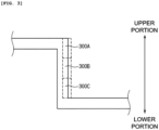
- FIG. 3 is an enlarged view illustrating the inner surface of the cup part 210 of the molded pouch exterior 200 for a secondary battery illustrated in FIG. 2 .
- the inner surface of the cup part 210 includes the first region 300A, the second region 300B, and the third region 300C.
- the first region 300A, the second region 300B, and the third region 300C may be parts of the sealant layer 130, respectively.
- the first region 300A represents an upper portion of the inner surface of the cup part 210
- the second region 300B represents a central portion of the inner surface of the cup part 210
- the third region 300C represents a lower portion of the inner surface of the cup part 210.
- the first region 300A may be a region from the uppermost end of the cup part 210 to 0.2d-0.3 d with respect to the depth d of the cup part 210
- the second region 300B may be a region from the end point of the first region 300A to 0.4d-0.5 d
- the third region 300C may be a region from the end point of the second region 300B to 0.2d-0.3 d.
- the first region 300A is a region in which the cup part 210 starts to be formed, and is a region in which a bending is generated by a punch in step (S2).
- the first region 300A may be a region in which a plurality of defects such as cracks are generated, and the degree of whitening may be severe, and the mechanical strength may be low.
- the second region 300B is a central portion of the inner surface of the cup part 210 and is a region in which no bending is generated
- the third region 300C is a lower portion of the inner surface of the cup 210 and is a region in which no bending is generated. Since the second region 300B and the third region 300C are less deformed by molding than the first region 300A, defects such as cracks are not generated. Accordingly, the degree of whitening of the second region 300B and the third region 300C may be low, and the mechanical strength may be somewhat high.
- the region to which the heat is applied may be the first region 300A which is the upper portion of the inner surface of the cup part 210, and the region to which the infrared rays are emitted, as a specific example of the method for applying the heat, may be the first region 300A which is the upper portion of the inner surface of the cup part 210.
- the first region 300A is a region in which a plurality of defects such as cracks are generated due to a large degree of deformation by molding as described above, and the infrared rays are emitted to the first region 300A and thus defects such as cracks or voids present in the sealant layer 130 may be effectively reduced or removed. Accordingly, a relatively weak part of the manufactured pouch case for a secondary battery may be reinforced, and the durability of the pouch case for a secondary battery may be improved.
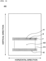
- the region to which the heat is applied may be an edge of the cup part 210 extending in the horizontal direction in the sealant layer 130. Since the edge of the cup part 210 extending in the horizontal direction in the sealant layer 130 is stretched in the vertical direction during the molding, cracks may be more easily formed than other parts, and thus the cracks formed by applying heat after the molding may be intensively removed to improve the durability.
- FIG. 4 exemplarily illustrates regions H1 and H2 to which the heat is applied.
- a pouch exterior for a secondary battery including a structure in which a 15 um-thick nylon layer as a first layer of the substrate layer, a 12 ⁇ m-thick polyethylene terephthalate layer as a second layer of the substrate layer, a 40 ⁇ m-thick aluminum alloy layer as the barrier layer, and an 80 ⁇ m-thick polypropylene layer as the sealant layer were stacked.
- the adhesive layers were disposed between the first layer and the second layer, and between the barrier layer and the first layer, respectively.
- both ends of the pouch exterior for a secondary battery were fixed using a stripper and a die, and the pouch exterior for a secondary battery was molded using a punch to form a cup part.
- the molding speed was 15 mm/sec, and the molding depth was 5.7 mm.
- Step (S3) Manufacturing the pouch case for a secondary battery by reducing cracks of the sealant layer of the pouch exterior for a secondary battery.
- the sealant layer of the molded pouch exterior for a secondary battery was heated to reduce the cracks present in the sealant layer.
- a method for emitting infrared rays to the sealant layer using an infrared lamp was used in the Example.
- the molded pouch exterior for a secondary battery was placed, and the infrared lamp was placed at a position spaced 5 cm from the pouch exterior.
- the wavelength of the infrared lamp was set to 2.5-50 ⁇ m, and the output of the infrared lamp was set to 200 W.
- the infrared lamp was used to emit infrared rays to the upper and lower portions (the regions indicated by H1 and H2 in FIG. 4 ) of the edge of the cup part extending in the horizontal direction of the sealant layer.
- the emitting time of the infrared rays was 4 seconds, and the infrared rays were emitted so that the surface temperature of the sealant layer reached about 40 °C.
- a pouch case for a secondary battery was manufactured in the same manner as in Example 1, except that in step (S3) above, the emitting time of the infrared rays using the infrared lamp was 12 seconds and the infrared rays were emitted so that the surface temperature of the sealant layer reached about 60 °C.
- a pouch case for a secondary battery was manufactured in the same manner as in Example 1, except that in step (S3) above, the emitting time of the infrared rays using the infrared lamp was 20 seconds and the infrared rays were emitted so that the surface temperature of the sealant layer reached about 80 °C.
- a pouch case for a secondary battery was manufactured in the same manner as in Example 1, except that in step (S3) above, the emitting time of the infrared rays using the infrared lamp was 28 seconds and the infrared rays were emitted so that the surface temperature of the sealant layer reached about 100 °C.
- a pouch case for a secondary battery was manufactured in the same manner as in Example 1, except that in step (S3) above, the emitting time of the infrared rays using the infrared lamp was 50 seconds and the infrared rays were emitted so that the surface temperature of the sealant layer reached about 150 °C.
- a pouch case for a secondary battery was manufactured in the same manner as in Example 1, except that in step (S3) above, the infrared rays were not emitted using the infrared lamp.
- FIG. 4 shows a location where the crack level is evaluated.
- FIG. 4 is a plan view of the molded pouch exterior for a secondary battery; A portion (M) which is spaced about 2 cm in the horizontal direction from one apex of a cup part 410 of each pouch exterior 400 for a secondary battery and corresponds to an upper portion of the inner surface of the cup part 410 was cut into 3 cm x 2.5 cm to be prepared as a specimen. After the specimen was attached onto the slide glass, the cracks were observed through an optical microscope.
- the crack level inside the sealant layer and the crack level on the surface of the sealant layer are expressed as 0 to 5 by checking, with the naked eye, the degree of the cracks through the photographs observed by the optical microscope. Going from 0 to 5 means that there are more cracks.
- Example 5 In the case of Example 5, after the pouch exterior for a secondary battery was molded, infrared rays were emitted so that a sufficient level of heat was transferred to the sealant layer, and accordingly, the materials inside the sealant layer were expanded, thereby removing all the cracks, but physical deformation such as curl was generated in the substrate layer or the barrier layer of the pouch exterior for a secondary battery.
Landscapes
- Chemical & Material Sciences (AREA)
- Chemical Kinetics & Catalysis (AREA)
- Electrochemistry (AREA)
- General Chemical & Material Sciences (AREA)
- Inorganic Chemistry (AREA)
- Sealing Battery Cases Or Jackets (AREA)
Applications Claiming Priority (2)
| Application Number | Priority Date | Filing Date | Title |
|---|---|---|---|
| KR1020210186151A KR102926461B1 (ko) | 2021-12-23 | 2021-12-23 | 이차 전지용 파우치 케이스의 제조 방법 |
| PCT/KR2022/021108 WO2023121361A1 (ko) | 2021-12-23 | 2022-12-22 | 이차 전지용 파우치 케이스의 제조 방법 |
Publications (2)
| Publication Number | Publication Date |
|---|---|
| EP4432430A1 true EP4432430A1 (de) | 2024-09-18 |
| EP4432430A4 EP4432430A4 (de) | 2025-04-02 |
Family
ID=86903095
Family Applications (1)
| Application Number | Title | Priority Date | Filing Date |
|---|---|---|---|
| EP22911994.6A Pending EP4432430A4 (de) | 2021-12-23 | 2022-12-22 | Verfahren zur herstellung eines beutelgehäuses für eine sekundärbatterie |
Country Status (6)
| Country | Link |
|---|---|
| US (1) | US20250062449A1 (de) |
| EP (1) | EP4432430A4 (de) |
| JP (1) | JP2024544713A (de) |
| KR (1) | KR102926461B1 (de) |
| CN (1) | CN118382956A (de) |
| WO (1) | WO2023121361A1 (de) |
Families Citing this family (1)
| Publication number | Priority date | Publication date | Assignee | Title |
|---|---|---|---|---|
| KR20250131127A (ko) * | 2024-02-26 | 2025-09-02 | 주식회사 엘지에너지솔루션 | 파우치 케이스의 성형 장치 및 파우치 케이스의 성형 방법 |
Family Cites Families (10)
| Publication number | Priority date | Publication date | Assignee | Title |
|---|---|---|---|---|
| EP1209094B1 (de) * | 2000-03-08 | 2006-06-14 | Dai Nippon Printing Co., Ltd. | Verpackungsmaterial für polymerzelle sowie verfahren zu dessen herstellung |
| JP4806837B2 (ja) * | 2000-04-07 | 2011-11-02 | 大日本印刷株式会社 | ポリマー電池外装体の製造方法 |
| JP2002231196A (ja) * | 2001-02-01 | 2002-08-16 | At Battery:Kk | 薄形電池の製造方法 |
| JP2002343311A (ja) * | 2001-05-18 | 2002-11-29 | Dainippon Printing Co Ltd | 電池用外装体およびその製造方法 |
| KR101837234B1 (ko) * | 2014-01-28 | 2018-03-09 | 주식회사 엘지화학 | 파우치 성형장치 |
| JP6266375B2 (ja) * | 2014-02-18 | 2018-01-24 | セイコーインスツル株式会社 | 電気化学セル |
| US10556400B2 (en) * | 2014-09-26 | 2020-02-11 | Dai Nippon Printing Co., Ltd. | Battery packaging material |
| JP6724483B2 (ja) * | 2015-03-31 | 2020-07-15 | 大日本印刷株式会社 | 電池用包装材料を成形するための金型 |
| JP7066965B2 (ja) * | 2016-06-02 | 2022-05-16 | 凸版印刷株式会社 | 蓄電装置用外装材 |
| KR102851596B1 (ko) * | 2019-10-22 | 2025-08-28 | 주식회사 엘지에너지솔루션 | 이차전지용 파우치 필름 성형 장치 및 방법 |
-
2021
- 2021-12-23 KR KR1020210186151A patent/KR102926461B1/ko active Active
-
2022
- 2022-12-22 WO PCT/KR2022/021108 patent/WO2023121361A1/ko not_active Ceased
- 2022-12-22 CN CN202280081854.XA patent/CN118382956A/zh active Pending
- 2022-12-22 US US18/720,769 patent/US20250062449A1/en active Pending
- 2022-12-22 EP EP22911994.6A patent/EP4432430A4/de active Pending
- 2022-12-22 JP JP2024535527A patent/JP2024544713A/ja active Pending
Also Published As
| Publication number | Publication date |
|---|---|
| US20250062449A1 (en) | 2025-02-20 |
| JP2024544713A (ja) | 2024-12-03 |
| CN118382956A (zh) | 2024-07-23 |
| EP4432430A4 (de) | 2025-04-02 |
| WO2023121361A1 (ko) | 2023-06-29 |
| KR102926461B1 (ko) | 2026-02-11 |
| KR20230096560A (ko) | 2023-06-30 |
Similar Documents
| Publication | Publication Date | Title |
|---|---|---|
| EP4435938A1 (de) | Verfahren zur herstellung eines beutelgehäuses für eine sekundärbatterie | |
| EP4432430A1 (de) | Verfahren zur herstellung eines beutelgehäuses für eine sekundärbatterie | |
| US20200067034A1 (en) | Crack-Prevention Sealing Block for Pouch-Shaped Secondary Batteries, Pouch-Shaped Battery Case Manufactured Using the Same, and Method of Sealing Pouch-Shaped Battery Case | |
| EP4439811A1 (de) | Beutelfolienlaminat und damit hergestelltes batteriegehäuse | |
| EP4015193B1 (de) | Vorrichtung und verfahren zur herstellung einer pouch-folie für sekundärbatterie | |
| CN113614888B (zh) | 保护膜及其粘贴方法以及半导体部件的制造方法 | |
| CN111152540B (zh) | 一种曲面贴合装置、贴合设备及曲面产品贴合方法 | |
| KR101866862B1 (ko) | 성형성이 향상된 셀 파우치 및 이의 제조 방법 | |
| JP2020521295A (ja) | 二次電池の製造方法、二次電池用パウチの製造方法及び二次電池用パウチ | |
| US7393706B2 (en) | Method of manufacturing optical semiconductor device, package molding jig, method of manufacturing package molding jig and manufacturing apparatus for package molding jig | |
| RU2211107C2 (ru) | Способ получения консервных банок посредством утонения стенок | |
| JP7486880B2 (ja) | ベンティング誘導部が形成されたパウチ型電池ケースの製造方法及び前記方法によって製造されたパウチ型電池ケース | |
| JP2025501547A (ja) | パウチフィルム積層体およびこれを用いて製造された電池ケース | |
| US20050006135A1 (en) | Airtight cable and a manufacturing method of airtight cable | |
| EP4106086B1 (de) | Herstellungsverfahren für pouchförmige batteriezellen, einschliesslich sekundärdichtung und pouchförmige batteriezelle, die dadurch hergestellt wird | |
| KR102804247B1 (ko) | 파우치형 케이스 성형장치 및 이를 이용한 파우치형 케이스의 제조방법 | |
| JPH11245928A (ja) | 食品容器 | |
| KR20230096558A (ko) | 이차 전지용 파우치 외장재의 불량 검사 방법 | |
| US6423174B1 (en) | Apparatus and insertless method for forming cavity substrates using coated membrane | |
| KR20260024795A (ko) | 파우치 케이스 제조 장치 및 파우치 케이스의 제조 방법 | |
| JPH1029019A (ja) | アルミニュウムフィルム冷間成形用の成形装置 | |
| JPH07119701A (ja) | アキュムレータ用ダイヤフラムの製造方法 |
Legal Events
| Date | Code | Title | Description |
|---|---|---|---|
| STAA | Information on the status of an ep patent application or granted ep patent |
Free format text: STATUS: THE INTERNATIONAL PUBLICATION HAS BEEN MADE |
|
| PUAI | Public reference made under article 153(3) epc to a published international application that has entered the european phase |
Free format text: ORIGINAL CODE: 0009012 |
|
| STAA | Information on the status of an ep patent application or granted ep patent |
Free format text: STATUS: REQUEST FOR EXAMINATION WAS MADE |
|
| 17P | Request for examination filed |
Effective date: 20240610 |
|
| AK | Designated contracting states |
Kind code of ref document: A1 Designated state(s): AL AT BE BG CH CY CZ DE DK EE ES FI FR GB GR HR HU IE IS IT LI LT LU LV MC ME MK MT NL NO PL PT RO RS SE SI SK SM TR |
|
| A4 | Supplementary search report drawn up and despatched |
Effective date: 20250228 |
|
| DAV | Request for validation of the european patent (deleted) | ||
| DAX | Request for extension of the european patent (deleted) | ||
| RIC1 | Information provided on ipc code assigned before grant |
Ipc: H01M 50/119 20210101ALI20250224BHEP Ipc: H01M 50/124 20210101ALI20250224BHEP Ipc: H01M 50/121 20210101ALI20250224BHEP Ipc: H01M 50/129 20210101ALI20250224BHEP Ipc: H01M 50/105 20210101AFI20250224BHEP |
|
| STAA | Information on the status of an ep patent application or granted ep patent |
Free format text: STATUS: EXAMINATION IS IN PROGRESS |
|
| 17Q | First examination report despatched |
Effective date: 20251202 |