EP4435308A1 - Ringelement - Google Patents
Ringelement Download PDFInfo
- Publication number
- EP4435308A1 EP4435308A1 EP22910839.4A EP22910839A EP4435308A1 EP 4435308 A1 EP4435308 A1 EP 4435308A1 EP 22910839 A EP22910839 A EP 22910839A EP 4435308 A1 EP4435308 A1 EP 4435308A1
- Authority
- EP
- European Patent Office
- Prior art keywords
- thin
- end portion
- ring member
- walled portion
- walled
- Prior art date
- Legal status (The legal status is an assumption and is not a legal conclusion. Google has not performed a legal analysis and makes no representation as to the accuracy of the status listed.)
- Pending
Links
- 238000010079 rubber tapping Methods 0.000 abstract description 11
- 230000002265 prevention Effects 0.000 description 16
- 238000006243 chemical reaction Methods 0.000 description 15
- 238000006073 displacement reaction Methods 0.000 description 10
- 238000010008 shearing Methods 0.000 description 6
- 238000010586 diagram Methods 0.000 description 5
- 238000007789 sealing Methods 0.000 description 2
- 230000003247 decreasing effect Effects 0.000 description 1
- 230000000694 effects Effects 0.000 description 1
- 230000037431 insertion Effects 0.000 description 1
- 238000003780 insertion Methods 0.000 description 1
Images



Classifications
-
- F—MECHANICAL ENGINEERING; LIGHTING; HEATING; WEAPONS; BLASTING
- F16—ENGINEERING ELEMENTS AND UNITS; GENERAL MEASURES FOR PRODUCING AND MAINTAINING EFFECTIVE FUNCTIONING OF MACHINES OR INSTALLATIONS; THERMAL INSULATION IN GENERAL
- F16L—PIPES; JOINTS OR FITTINGS FOR PIPES; SUPPORTS FOR PIPES, CABLES OR PROTECTIVE TUBING; MEANS FOR THERMAL INSULATION IN GENERAL
- F16L37/00—Couplings of the quick-acting type
- F16L37/08—Couplings of the quick-acting type in which the connection between abutting or axially overlapping ends is maintained by locking members
- F16L37/084—Couplings of the quick-acting type in which the connection between abutting or axially overlapping ends is maintained by locking members combined with automatic locking
- F16L37/088—Couplings of the quick-acting type in which the connection between abutting or axially overlapping ends is maintained by locking members combined with automatic locking by means of a split elastic ring
-
- F—MECHANICAL ENGINEERING; LIGHTING; HEATING; WEAPONS; BLASTING
- F16—ENGINEERING ELEMENTS AND UNITS; GENERAL MEASURES FOR PRODUCING AND MAINTAINING EFFECTIVE FUNCTIONING OF MACHINES OR INSTALLATIONS; THERMAL INSULATION IN GENERAL
- F16L—PIPES; JOINTS OR FITTINGS FOR PIPES; SUPPORTS FOR PIPES, CABLES OR PROTECTIVE TUBING; MEANS FOR THERMAL INSULATION IN GENERAL
- F16L21/00—Joints with sleeve or socket
- F16L21/08—Joints with sleeve or socket with additional locking means
-
- F—MECHANICAL ENGINEERING; LIGHTING; HEATING; WEAPONS; BLASTING
- F16—ENGINEERING ELEMENTS AND UNITS; GENERAL MEASURES FOR PRODUCING AND MAINTAINING EFFECTIVE FUNCTIONING OF MACHINES OR INSTALLATIONS; THERMAL INSULATION IN GENERAL
- F16L—PIPES; JOINTS OR FITTINGS FOR PIPES; SUPPORTS FOR PIPES, CABLES OR PROTECTIVE TUBING; MEANS FOR THERMAL INSULATION IN GENERAL
- F16L27/00—Adjustable joints; Joints allowing movement
- F16L27/12—Adjustable joints; Joints allowing movement allowing substantial longitudinal adjustment or movement
Definitions
- the present invention relates to a ring member used for a pipe joint.
- the ring member according to the present invention is fitted in a groove formed in the outer circumference of a spigot of one of pipes to be joined to each other to form a protrusion that protrudes from the outer surface of the spigot and extends in the circumferential direction of the spigot.
- the protrusion formed according to the present invention comes into contact with a lock ring located inside a socket of the other of the pipes to be joined to each other, thereby preventing the pipes from being separated.
- Japanese Patent Laid-Open No. 9-196262 discloses a ring member of this type.
- the ring member is fitted in a groove formed in the outer circumference of a spigot of a pipe to form, on the outer circumference of the spigot, a protrusion for preventing pipes joined to each other from being separated.
- the ring member has a split part split at a point in the circumferential direction, which is formed by one end portion of the ring member in the circumferential direction and another end portion of the ring member in the circumferential direction.
- the one end portion and the other end portion overlap one another in the radial direction of the pipes, with the one end portion located on the inner side in the radial direction of the pipes and the other end portion located on the outer side in the radial direction of the pipes, and are connected to each other by a connector member.
- the ring member according to Japanese Patent Laid-Open No. 9-196262 comes into contact with a lock ring in a state where the ring member is fitted in a groove and thus receives a reaction force (removal prevention force) from the lock ring. Therefore, the other end portion in the circumferential direction of the ring member, which is located on the outer side in the radial direction of the pipes when the one end portion and the other end portion overlap one another and is to come into contact with the lock ring, tends to be displaced in the opposite direction to the spigot removal direction with respect to the one end portion that is located on the inner side in the radial direction of the pipes when the one end portion and the other end portion overlap one another and is fitted in the groove. Therefore, an excessive shearing force acts on the connector member that connects the one end portion and the other end portion in the circumferential direction of the ring member to each other.
- An object of the present invention is to provide a ring member that can reduce a shearing force acting on a connector member when the ring member comes into contact with a lock ring.
- a ring member according to the present invention that attains the object described above is used for a pipe joint that prevents a spigot of a first pipe from separating from a socket of a second pipe.
- the ring member includes: a split part split in the circumferential direction at a point in the circumferential direction; one end portion in the circumferential direction and another end portion in the circumferential direction, the one end portion and the other end portion forming the split part; and a connector member that connects the one end portion and the other end portion of the split part to each other in a state where the one end portion and the other end portion overlap one another in the radial direction of the first pipe.
- the one end portion is located on the inner side than the other end portion in the radial direction of the first pipe.
- the ring member is configured in such a manner that the one end portion is fitted into a groove formed in the outer circumference of the spigot and the other end portion can come into contact with a lock ring disposed inside the socket.
- the ring member has, on one of the one end portion and the other end portion, an engaging portion that is engaged with the other of the one end portion and the other end portion in the axial direction of the pipes when the ring member comes into contact with the lock ring.
- a reaction force (removal prevention force) from the lock ring is received by one of the one end portion and the other end portion of the split part of the ring member that is fitted in the groove via the engaging portion of the other of the one end portion and the other end portion, so that the displacement of the one end portion and the other end portion with respect to each other in the axial direction of the pipes is restricted. Therefore, the shearing force acting on the connector member due to the force that causes the displacement is reduced.
- the engaging portion is preferably provided on one of the one end portion and the other end portion of the split part on the side in the axial direction of the pipes where the ring member comes into contact with the lock ring.
- the one end portion and the other end portion of the split part can be engaged with each other at a position close to the position where the ring member and the lock ring come into contact with each other.
- the engaging portion is preferably provided on the other end portion and extends inwardly in the radial direction of the pipes.
- the engaging portion can be fitted into the groove of the spigot, and the one end portion and the other end portion forming the split part can be engaged with each other in the groove.
- one of the one end portion and the other end portion forming the split part has the engaging portion that is engaged with the other of the one end portion and the other end portion forming the split part when the ring member comes into contact with the lock ring. Therefore, the reaction force (removal prevention fore) from the lock ring that occurs as a result of the ring member coming into contact with the lock ring is received by the other end portion forming the split part and is also received by the one end portion forming the split part via the engaging portion.
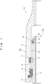
- the ring member 20 As shown in FIGS. 1 and 2 , the ring member 20 according to the first embodiment of the present invention is used for a pipe joint 10.
- the pipe joint 10 has a spigot 11 and a socket 12.
- the spigot 11 is formed at an end of a first pipe 10A.
- the socket 12 is formed at an end of a second pipe 10B that is to be joined to the first pipe 10A.
- the spigot 11 is inserted into the socket 12.
- the ring member 20 protrudes from an outer circumference 11a of the spigot 11 and comes into contact with a lock ring 13 that is located inside the socket 12, thereby preventing the spigot 11 from separating from the socket 12.
- a housing groove 14 for a sealing member is formed in an inner circumference of a distal end portion of the socket 12.
- a sealing member 15 made of rubber is fitted in the housing groove 14.
- a housing groove 16 for the lock ring is formed in a part of the inner circumference of the socket 12 deeper than the housing groove 14.
- the lock ring 13 is fitted in the housing groove 16.
- a ring 17 for centering made of rubber is interposed between an inner circumference surface of the housing groove 16 and an outer circumference surface of the lock ring 13. The ring 17 aligns the axis of the lock ring 13 with the axis of the socket 12.
- annular groove 18 is formed in the outer circumference 11a of a distal end portion of the spigot 11.
- the ring member 20 is fitted in the annular groove 18.
- the ring member 20 is fitted in the annular groove 18 to form a protrusion that comes into contact with the lock ring 13.
- the ring member 20 is formed by a split body 21 having a split part 22 split in the circumferential direction at a point in the circumferential direction.
- the ring member 20 is an open ring member.
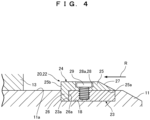
- the split part 22 of the ring member 20 has a first thin-walled portion 23 having a curved shape located on the inner circumference side and a second thin-walled portion 24 having a curved shape located on the outer circumference side.
- the first thin-walled portion 23 is formed at one end portion in the circumferential direction of the body 21, which constitutes the split part 22.
- the inner circumference surface of the first thin-walled portion 23 is continuous with the inner circumference surface of the body 21. In other words, the inner circumference surface of the first thin-walled portion 23 extends at the same radial position with the same curvature as the inner circumference surface of the body 21.
- the second thin-walled portion 24 is formed at the other end portion in the circumferential direction of the body 21, which constitutes the split part 22.
- the outer circumference surface of the second thin-walled portion 24 is continuous with the outer circumference surface of the body 21. In other words, the outer circumference surface of the second thin-walled portion 24 extends at the same radial position with the same curvature as the outer circumference surface of the body 21.
- the first thin-walled portion 23 and the second thin-walled portion 24 overlap one another in the radial direction of the ring member 20 (the radial direction of the first pipe 10A).
- the first thin-walled portion 23 and the second thin-walled portion 24 are arranged in such a manner that the outer circumference surface of the first thin-walled portion 23 is in contact with the inner circumference surface of the second thin-walled portion 24.
- the split part 22 of the body 21 is formed so that the sum of the thickness of the first thin-walled portion 23 (the thickness in the radial direction of the ring member 20) and the thickness of the second thin-walled portion 24 (the thickness in the radial direction of the ring member 20) is equal to the thickness of the other part of the body 21 than the split part 22 (the thickness in the radial direction of the ring member 20) .
- the first thin-walled portion 23 and the second thin-walled portion 24 overlap one another over a predetermined length in the circumferential direction and each have a length in the circumferential direction greater than the length of the part thereof overlapping the other. With the first thin-walled portion 23 and the second thin-walled portion 24 configured as described above, the ring member 20 can be increased or decreased in diameter to some extent while the first thin-walled portion 23 and the second thin-walled portion 24 are kept overlapping one another.
- the first thin-walled portion 23 is located on the inner circumference side of the ring member 20 when overlapping with the second thin-walled portion 24.
- the first thin-walled portion 23 is fitted into the annular groove 18 of the spigot 11 when the ring member 20 is attached to the outer circumference 11a of the spigot 11.
- the annular groove 18 has a rectangular cross section.
- the ring member 20 also has a rectangular cross section that corresponds to that of the annular groove 18.
- the thickness of the first thin-walled portion 23 (the thickness in the radial direction of the ring member 20) is approximately equal to or slightly smaller than the depth of the angular groove 18 in the radial direction of the spigot 11.
- the width dimension of the first thin-walled portion 23 (the dimension in the axial direction of the ring member 20) is smaller than the dimension in the width direction of the annular groove 18 (the dimension in the axial direction of the pipe joint 10).
- the second thin-walled portion 24 has a L-shaped cross section.
- the second thin-walled portion 24 overlaps with the first thin-walled portion 23 and is located on the outer circumference side of the ring member 20.
- the second thin-walled portion 24 protrudes in the radial direction of the spigot 11 from the outer circumference 11a of the spigot 11 when the first thin-walled portion 23 is fitted into the annular groove 18 of the spigot 11.
- the second thin-walled portion 24 serves as a protrusion of the spigot 11 that comes into contact with the lock ring 13. That is, the second thin-walled portion 24 comes into contact with the lock ring 13 when the spigot 11 is separating from the socket 12.
- the second thin-walled portion 24 has a contact portion 25 and an engaging portion 26.
- the engaging portion 26 extends in the vertical direction (toward the inner side in the radial direction) from one end in the axial direction of the contact portion 25, and thus the second thin-walled portion 24 has the L-shaped cross section as described above.
- the contact portion 25 rests on the outer circumference surface of the first thin-walled portion 23.
- the contact portion 25 protrudes from the outer circumference 11a of the spigot 11 when the ring member 20 is fitted into the annular groove 18. Since the contact portion 25 protrudes from the outer circumference 11a of the spigot 11, the contact portion 25 comes into contact with the lock ring 13 when the spigot 11 is separating from the socket 12.
- the end portion of the contact portion 25 on the tip end side of the spigot 11 in the axial direction that is, the end portion of the contact portion 25 opposite to the end portion that comes into contact with the lock ring 13, is tapered toward the tip end of the spigot 11 and thus has an inclined surface 27.
- the engaging portion 26 When the contact portion 25 comes into contact with the lock ring 13, the engaging portion 26 is engaged with the first thin-walled portion 23.
- the engaging portion 26 protrudes inwardly in the radial direction from the contact portion 25.
- the engaging portion 26 is formed at the end of the contact portion 25 of the second thin-walled portion 24 that is located toward the lock ring 13.
- the engaging portion 26 When the ring member 20 is attached to the outer circumference 11a of the spigot 11, the engaging portion 26 is fitted into a part of the annular grove 18 of the spigot 11 that is located toward the lock ring 13 and is not occupied by the first thin-walled portion 23.
- the length of the engaging portion 26 protruding inwardly in the radial direction is approximately equal to or slightly shorter than the depth of the annular groove 18 in the radial direction of the spigot 11.
- a hole 28 for insertion of a connector member for connection with the first thin-walled portion 23 is formed in a part of the second thin-walled portion 24, and the hole 28 penetrates the second thin-walled portion 24 in the radial direction of the pipe.
- the hole 28 has a wide portion 28a on the outer circumference surface side of the second thin-walled portion 24.
- the head of the tapping screw 29 is housed in the wide portion 28a. Since the first thin-walled portion 23 and the second thin-walled portion 24 are connected by the tapping screw 29, the ring member 20 is fixed to the outer circumference of the spigot 11 with a part of the ring member 20 protruding in the radial direction from the outer circumference 11a of the spigot 11 of the first pipe 10A.
- the first thin-walled portion 23 is connected to the second thin-walled portion 24 in a state where the first thin-walled portion 23 is located in a space defined by a curved surface 25a of the second thin-walled portion 24 and a first vertical surface 26a of the engaging portion 26.
- the curved surface 25a of the second thin-walled portion 24 is a curved surface on the inner side in the radial direction of the contact portion 25 of the second thin-walled portion 24.
- the first vertical surface 26a of the engaging portion 26 is a side surface of the engaging portion 26 located toward the first thin-walled portion 23 that extends in the radial direction perpendicularly to the contact portion 25. Since the first thin-walled portion 23 and the second thin-walled portion 24 overlap one another, the first thin-walled portion 23 is held in the annular groove 18 in the state where the first thin-walled portion 23 is covered by the contact portion 25 and engaging portion 26 of the second thin-walled portion 24.
- the ring member 20 When the ring member 20 comes into contact with the lock ring 13, the ring member 20 receives a reaction force (removal prevention force) from the lock ring 13 in the opposite direction to the removal direction R of the spigot 11.
- the second thin-walled portion 24 of the split part 22 of the body 21 of the ring member 20 receives the reaction force (removal prevention force) from the lock ring 13. More specifically, the second thin-walled portion 24 receives the reaction force (removal prevention force) from the lock ring 13 at a second vertical surface 25b of the contact portion 25.
- the second vertical surface 25b of the contact portion 25 is a vertical surface that protrudes from the outer circumference 11a of the spigot 11 in the radial direction of the pipe and faces toward the lock ring 13 when the body 21 is fitted in the annular groove 18.
- the second thin-walled portion 24 When the second thin-walled portion 24 receives the reaction force (removal prevention force) from the lock ring 13, the second thin-walled portion 24 would otherwise be displaced toward the first thin-walled portion 23 in the opposite direction to the removal direction R of the spigot 11. At this point in time, however, the first vertical surface 26a of the engaging portion 26 of the second thin-walled portion 24 comes into contact with a third vertical surface 23a of the first thin-walled portion 23 in the annular groove 18.
- the third vertical surface 23a of the first thin-walled portion 23 is a surface of the first thin-walled portion 23 that is perpendicular to the bottom surface of the annular groove 18 when the first thin-walled portion 23 is fitted in the annular groove 18 and faces the first vertical surface 26a of the engaging portion 26 of the second thin-walled portion 24.
- the third vertical surface 23a of the first thin-walled portion 23 fitted in the annular groove 18 receives the reaction force (removal prevention force) from the lock ring 13 via the engaging portion 26 of the second thin-walled portion 24, so that the displacement of the second thin-walled portion 24 with respect to the first thin-walled portion 23 in the opposite direction to the removal direction R of the spigot 11 is restricted.
- the second thin-walled portion 24 forming the split part 22 of the body 21 of the ring member 20 has the engaging portion 26 that is engaged with the first thin-walled portion 23 that forms the split part 22 when the body 21 of the ring member 20 comes into contact with the lock ring 13. Therefore, the reaction force (removal prevention force) from the lock ring 13 that occurs when the body 21 comes into contact with the lock ring 13 is received by the second thin-walled portion 24 and is also received by the first thin-walled portion 23 via the engaging portion 26.
- the second thin-walled portion 24 has the engaging portion 26 that is to be engaged with the first thin-walled portion 23 on the side where the contact portion 25 comes into contact with the lock ring 13.
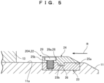
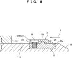
- an engaging portion 26 may be provided in a middle part of a second thin-walled portion 24 in the axial direction.
- a first recess portion 23b that can be engaged with the engaging portion 26 is formed in a middle part of a first thin-walled portion 23.
- the engaging portion 26 is fitted in the first recess portion 23b.
- the other components than those described above are the same as those in the first embodiment.
- the first recess portion 23b is a groove extending in the circumferential direction in which the engaging portion 26 of the second thin-walled portion 24 can be fitted.
- the present invention is not limited to this.
- a first thin-walled portion 23 to be fitted into an annular groove 18 may have an engaging portion 26. In these cases, the engaging portion 26 protrudes outwardly in the radial direction.
- the engaging portion 26 may be provided on the side where the ring member 20B comes into contact with a lock ring 13. In this case, the engaging portion 26 comes into contact with not only the lock ring 13 but also a second vertical surface 25b of a second thin-walled portion 24.
- the second vertical surface 25b is an end surface of the thin-walled portion 24 located toward the lock ring 13.
- an engaging portion 26 may be provided on a first thin-walled portion 23 on the opposite side to a lock ring 13. In this case, the engaging portion 26 comes into contact with a fourth vertical surface 25C of a second thin-walled portion 24.
- the fourth vertical surface 25C is an end surface of the second thin-walled portion 24 located on the opposite side to the lock ring 13.
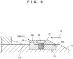
- an engaging portion 26 may be provided on a middle part of a first thin-walled portion 23 in the axial direction.
- a second recess portion 25d that can be engaged with the engaging portion 26 fitted therein is formed in a middle part of a second thin-walled portion 24.
- the second recess portion 25d is a groove extending in the circumferential direction in which the engaging portion 26 of the first thin-walled portion 23 can be fitted.
- first thin-walled portion 23 and the second thin-walled portion 24 are connected to each other by the tapping screw 29 as a fastener element in the first to fifth embodiments, the present invention is not limited to this.
- the first thin-walled portion 23 and the second thin-walled portion 24 may be connected to each other by connector members formed by other fastener elements, such as a rivet, or other connector members of the non-fastening type.
Landscapes
- Engineering & Computer Science (AREA)
- General Engineering & Computer Science (AREA)
- Mechanical Engineering (AREA)
- Joints With Sleeves (AREA)
- Joints Allowing Movement (AREA)
- Mutual Connection Of Rods And Tubes (AREA)
Applications Claiming Priority (2)
| Application Number | Priority Date | Filing Date | Title |
|---|---|---|---|
| JP2021205637A JP7634471B2 (ja) | 2021-12-20 | 2021-12-20 | リング部材 |
| PCT/JP2022/044660 WO2023120125A1 (ja) | 2021-12-20 | 2022-12-05 | リング部材 |
Publications (2)
| Publication Number | Publication Date |
|---|---|
| EP4435308A1 true EP4435308A1 (de) | 2024-09-25 |
| EP4435308A4 EP4435308A4 (de) | 2025-03-19 |
Family
ID=86902169
Family Applications (1)
| Application Number | Title | Priority Date | Filing Date |
|---|---|---|---|
| EP22910839.4A Pending EP4435308A4 (de) | 2021-12-20 | 2022-12-05 | Ringelement |
Country Status (7)
| Country | Link |
|---|---|
| US (1) | US12565949B2 (de) |
| EP (1) | EP4435308A4 (de) |
| JP (1) | JP7634471B2 (de) |
| CN (1) | CN118414517A (de) |
| CA (1) | CA3240742A1 (de) |
| TW (1) | TW202338246A (de) |
| WO (1) | WO2023120125A1 (de) |
Family Cites Families (11)
| Publication number | Priority date | Publication date | Assignee | Title |
|---|---|---|---|---|
| JPS5176626A (ja) * | 1974-12-26 | 1976-07-02 | Kubota Ltd | Taishinkantsugite |
| GB1520332A (en) * | 1975-05-16 | 1978-08-09 | Kubota Ltd | Separationprevented pipe joint construction |
| JPH09196262A (ja) | 1996-01-17 | 1997-07-29 | Kubota Corp | 挿口に突部を有する管およびその製造方法 |
| GB2308629B (en) * | 1995-12-28 | 1999-07-14 | Kubota Kk | Pipe having ridge on spigot and method of forming the ridge |
| JP3253853B2 (ja) * | 1996-04-16 | 2002-02-04 | 有限会社ケーテック | 揺動伸縮自在管継手 |
| JP4070045B2 (ja) * | 1998-02-12 | 2008-04-02 | コスモ工機株式会社 | 流体管の抜出防止装置 |
| JP3988846B2 (ja) * | 1998-03-30 | 2007-10-10 | コスモ工機株式会社 | 流体管の抜出防止装置 |
| JP2001280562A (ja) | 2000-03-31 | 2001-10-10 | Kurimoto Ltd | 管継手におけるロックリング |
| GB2455085A (en) * | 2007-11-27 | 2009-06-03 | Fergus Johnathan Ardern | Clip comprising a resiliently deformable split ring |
| KR102185497B1 (ko) * | 2020-03-23 | 2020-12-02 | 주식회사 고리 | 꺽임강도 및 내진 기능이 강화된 관 |
| JP2025076626A (ja) | 2023-11-02 | 2025-05-16 | 日東工業株式会社 | 電気電子機器収納用箱集合体及び電気電子機器収納用箱 |
-
2021
- 2021-12-20 JP JP2021205637A patent/JP7634471B2/ja active Active
-
2022
- 2022-12-05 US US18/721,752 patent/US12565949B2/en active Active
- 2022-12-05 EP EP22910839.4A patent/EP4435308A4/de active Pending
- 2022-12-05 WO PCT/JP2022/044660 patent/WO2023120125A1/ja not_active Ceased
- 2022-12-05 CA CA3240742A patent/CA3240742A1/en active Pending
- 2022-12-05 CN CN202280084080.6A patent/CN118414517A/zh active Pending
- 2022-12-19 TW TW111148786A patent/TW202338246A/zh unknown
Also Published As
| Publication number | Publication date |
|---|---|
| WO2023120125A1 (ja) | 2023-06-29 |
| US12565949B2 (en) | 2026-03-03 |
| CN118414517A (zh) | 2024-07-30 |
| JP7634471B2 (ja) | 2025-02-21 |
| EP4435308A4 (de) | 2025-03-19 |
| JP2023091102A (ja) | 2023-06-30 |
| US20240353036A1 (en) | 2024-10-24 |
| TW202338246A (zh) | 2023-10-01 |
| CA3240742A1 (en) | 2023-06-29 |
Similar Documents
| Publication | Publication Date | Title |
|---|---|---|
| US5707085A (en) | Fluid coupling | |
| US5647685A (en) | Frictional type connector for connecting a rotator to a shaft | |
| EP0855546A1 (de) | Rohrverbindung | |
| US4413845A (en) | Pipe couplings | |
| US4863199A (en) | Separation preventive pipe joint | |
| JP5213636B2 (ja) | 継手用シール装置およびこれを備えた流体継手 | |
| KR100322637B1 (ko) | 관이음부 | |
| EP1681477A1 (de) | Federring | |
| US20090026762A1 (en) | Assembly of male and female members | |
| CN114585847A (zh) | 管接头 | |
| KR101064549B1 (ko) | 내진기능을 가지는 관이음매 | |
| EP4435308A1 (de) | Ringelement | |
| EP1950472A1 (de) | Dichtungsvorrichtung | |
| CN116490712B (zh) | 管接头、压圈及管的接合方法 | |
| WO2021126215A1 (en) | Fluid connector with an expansion ring | |
| JP2004211831A (ja) | 管の継手構造 | |
| US12529424B2 (en) | Gasket | |
| JP4023936B2 (ja) | フレキシブルチューブ用継手 | |
| JP4488635B2 (ja) | フレキシブルチューブ用継手および同継手用のリテーナ | |
| JP3041477B2 (ja) | 管接続装置 | |
| JP2000104871A (ja) | 管継手用ロックリング及び管継手 | |
| US12160066B2 (en) | Connector assembly, connector for such a connector assembly, and method for installing the connector assembly | |
| JP2561694B2 (ja) | 管継手 | |
| JP3154896B2 (ja) | 離脱防止管継手 | |
| JPH10110881A (ja) | コネクターとパイプの接続構造体 |
Legal Events
| Date | Code | Title | Description |
|---|---|---|---|
| STAA | Information on the status of an ep patent application or granted ep patent |
Free format text: STATUS: THE INTERNATIONAL PUBLICATION HAS BEEN MADE |
|
| PUAI | Public reference made under article 153(3) epc to a published international application that has entered the european phase |
Free format text: ORIGINAL CODE: 0009012 |
|
| STAA | Information on the status of an ep patent application or granted ep patent |
Free format text: STATUS: REQUEST FOR EXAMINATION WAS MADE |
|
| 17P | Request for examination filed |
Effective date: 20240619 |
|
| AK | Designated contracting states |
Kind code of ref document: A1 Designated state(s): AL AT BE BG CH CY CZ DE DK EE ES FI FR GB GR HR HU IE IS IT LI LT LU LV MC ME MK MT NL NO PL PT RO RS SE SI SK SM TR |
|
| RAP3 | Party data changed (applicant data changed or rights of an application transferred) |
Owner name: KUBOTA CORPORATION |
|
| A4 | Supplementary search report drawn up and despatched |
Effective date: 20250217 |
|
| RIC1 | Information provided on ipc code assigned before grant |
Ipc: F16L 37/088 20060101ALI20250211BHEP Ipc: F16L 27/12 20060101ALI20250211BHEP Ipc: F16L 21/08 20060101AFI20250211BHEP |
|
| DAV | Request for validation of the european patent (deleted) | ||
| DAX | Request for extension of the european patent (deleted) |