EP4435313A1 - Système et procédé de surveillance d'une zone dangereuse d'une machine - Google Patents
Système et procédé de surveillance d'une zone dangereuse d'une machine Download PDFInfo
- Publication number
- EP4435313A1 EP4435313A1 EP24160435.4A EP24160435A EP4435313A1 EP 4435313 A1 EP4435313 A1 EP 4435313A1 EP 24160435 A EP24160435 A EP 24160435A EP 4435313 A1 EP4435313 A1 EP 4435313A1
- Authority
- EP
- European Patent Office
- Prior art keywords
- sensor
- machine
- area
- control
- evaluation unit
- Prior art date
- Legal status (The legal status is an assumption and is not a legal conclusion. Google has not performed a legal analysis and makes no representation as to the accuracy of the status listed.)
- Granted
Links
Images

Classifications
-
- F—MECHANICAL ENGINEERING; LIGHTING; HEATING; WEAPONS; BLASTING
- F16—ENGINEERING ELEMENTS AND UNITS; GENERAL MEASURES FOR PRODUCING AND MAINTAINING EFFECTIVE FUNCTIONING OF MACHINES OR INSTALLATIONS; THERMAL INSULATION IN GENERAL
- F16P—SAFETY DEVICES IN GENERAL; SAFETY DEVICES FOR PRESSES
- F16P3/00—Safety devices acting in conjunction with the control or operation of a machine; Control arrangements requiring the simultaneous use of two or more parts of the body
- F16P3/12—Safety devices acting in conjunction with the control or operation of a machine; Control arrangements requiring the simultaneous use of two or more parts of the body with means, e.g. feelers, which in case of the presence of a body part of a person in or near the danger zone influence the control or operation of the machine
- F16P3/14—Safety devices acting in conjunction with the control or operation of a machine; Control arrangements requiring the simultaneous use of two or more parts of the body with means, e.g. feelers, which in case of the presence of a body part of a person in or near the danger zone influence the control or operation of the machine the means being photocells or other devices sensitive without mechanical contact
- F16P3/142—Safety devices acting in conjunction with the control or operation of a machine; Control arrangements requiring the simultaneous use of two or more parts of the body with means, e.g. feelers, which in case of the presence of a body part of a person in or near the danger zone influence the control or operation of the machine the means being photocells or other devices sensitive without mechanical contact using image capturing devices
-
- B—PERFORMING OPERATIONS; TRANSPORTING
- B25—HAND TOOLS; PORTABLE POWER-DRIVEN TOOLS; MANIPULATORS
- B25J—MANIPULATORS; CHAMBERS PROVIDED WITH MANIPULATION DEVICES
- B25J9/00—Program-controlled manipulators
- B25J9/16—Program controls
- B25J9/1674—Program controls characterised by safety, monitoring, diagnostic
- B25J9/1676—Avoiding collision or forbidden zones
-
- G—PHYSICS
- G05—CONTROLLING; REGULATING
- G05B—CONTROL OR REGULATING SYSTEMS IN GENERAL; FUNCTIONAL ELEMENTS OF SUCH SYSTEMS; MONITORING OR TESTING ARRANGEMENTS FOR SUCH SYSTEMS OR ELEMENTS
- G05B19/00—Program-control systems
- G05B19/02—Program-control systems electric
- G05B19/04—Program control other than numerical control, i.e. in sequence controllers or logic controllers
- G05B19/042—Program control other than numerical control, i.e. in sequence controllers or logic controllers using digital processors
- G05B19/0428—Safety, monitoring
-
- B—PERFORMING OPERATIONS; TRANSPORTING
- B25—HAND TOOLS; PORTABLE POWER-DRIVEN TOOLS; MANIPULATORS
- B25J—MANIPULATORS; CHAMBERS PROVIDED WITH MANIPULATION DEVICES
- B25J19/00—Accessories fitted to manipulators, e.g. for monitoring, for viewing; Safety devices combined with or specially adapted for use in connection with manipulators
- B25J19/02—Sensing devices
- B25J19/021—Optical sensing devices
- B25J19/022—Optical sensing devices using lasers
-
- B—PERFORMING OPERATIONS; TRANSPORTING
- B25—HAND TOOLS; PORTABLE POWER-DRIVEN TOOLS; MANIPULATORS
- B25J—MANIPULATORS; CHAMBERS PROVIDED WITH MANIPULATION DEVICES
- B25J19/00—Accessories fitted to manipulators, e.g. for monitoring, for viewing; Safety devices combined with or specially adapted for use in connection with manipulators
- B25J19/02—Sensing devices
- B25J19/021—Optical sensing devices
- B25J19/023—Optical sensing devices including video camera means
-
- G—PHYSICS
- G05—CONTROLLING; REGULATING
- G05B—CONTROL OR REGULATING SYSTEMS IN GENERAL; FUNCTIONAL ELEMENTS OF SUCH SYSTEMS; MONITORING OR TESTING ARRANGEMENTS FOR SUCH SYSTEMS OR ELEMENTS
- G05B2219/00—Program-control systems
- G05B2219/20—Pc systems
- G05B2219/24—Pc safety
- G05B2219/24024—Safety, surveillance
Definitions
- the present invention relates to a system for monitoring a danger area of a machine according to the preamble of claim 1 and a method for monitoring a danger area of a machine according to the preamble of claim 9.
- the state of the art for protecting industrial robots is the use of safety laser scanners to secure areas or light grids to secure access.
- the presence of a person or other object in the danger zone is detected and the dangerous movement of the robot is switched off.
- Distance and speed monitoring represents a higher level of development of this well-known approach, in which a robot is initially slowed down depending on the distance between the person and the robot and the approach speed, which reduces the risk, and is only stopped when a further approach threshold is exceeded. Alternatively, the robot is redirected to free areas to avoid a hazard.
- An object of the invention is to provide an improved system and an improved method in which persons can be in the danger zone and yet the machine is safely shut down if a danger to the person could arise.
- a system for monitoring a danger area of a machine with at least one sensor with at least one spatial monitoring area for monitoring the danger area, and a control and evaluation unit, wherein the sensor is designed to cyclically send 3D data of the monitoring area to the control and evaluation unit, wherein the sensor is further designed to generate at least one protection area in the monitoring area, wherein the control and evaluation unit is designed to compare the received 3D data of the monitoring area with known position data of the machine and to check for agreement, wherein the control and evaluation unit is designed to localize objects in the monitoring area of the sensor based on the 3D data and to determine their distance from a dangerous part of the machine, wherein the control and evaluation unit is designed to bridge the sensor with the protection area as long as there is a match in the position data and not to bridge the sensor with the protection area if there is no match in the position data and not to bridge the sensor with the protection area if the Distance of objects to at least one dangerous part of the machine falls below predefined first distance values.
- the object is further achieved according to claim 9 by a method for monitoring a danger area of a machine, with at least one sensor with at least one spatial monitoring area for monitoring the danger area, and a control and evaluation unit, wherein the sensor cyclically sends 3D data of the monitoring area to the control and evaluation unit, wherein the sensor generates at least one protection area in the monitoring area, wherein the control and evaluation unit compares the received 3D data of the monitoring area with known position data of the machine and checks for agreement, wherein the control and evaluation unit localizes objects in the monitoring area of the sensor based on the 3D data and determines their distance from a dangerous part of the machine, wherein the control and evaluation unit bridges the sensor with the protection area as long as there is a match in the position data and does not bridge the sensor with the protection area if there is no match in the position data, and does not bridge the sensor with the protection area if the distance of objects to at least one dangerous part of the machine exceeds predefined first distance values falls below.
- muting i.e. a bridging or a conditional bridging of a safety function of the machine
- a non-safe control and evaluation unit or a control unit that is designed to compare 3D image data of the danger zone of the sensor with the known position data of the robot and to check for consistency.
- control and evaluation unit is designed to locate other objects in the sensor's field of view using the sensor's 3D data and to determine their distance from the robot.
- these functions do not have to be carried out in accordance with the functional safety specifications.
- One or more sensors are preferably safety-certified. These record 3D data of the danger area in real time and with synchronization information and deliver the data to the control and evaluation unit.
- the sensor for example a safe 3D camera with integrated protection area function, is designed for classic monitoring of the approach area around the machine.
- a safe controller for binary switching signals as a control and evaluation unit in order to combine activation signals or bridging signals and the signal from the sensor.
- the basic idea of the invention is that the actual protection of the machine is carried out using a simple protection area function of the sensor or safety sensor. This means that if a person is present in the protection area, a shutdown signal is sent to the machine or its control system or its machine control system. This protection is tried and tested and can be implemented with a high degree of reliability. In the following, it is referred to as the primary safety function.
- the other parts of the system provide a function that depends on the situation and the consistency and plausibility of the remaining information (3D data and machine position data) generates a signal to deactivate or bypass the primary safety function.
- the sensor(s) or 3D sensors provide information or 3D data about the machine's environment, which are used in two different ways.
- This 3D data is used to check whether the areas in which the machine control system should contain moving parts of the machine are also occupied by an object in the 3D data or in the 3D image. This can be checked with a precise location using a so-called voxel grid approach, for example. Volume pixels are created, with a pixel or voxel corresponding to a point in space. This sub-function is used for plausibility and represents an effective check of the proper functioning of the sensor and the machine control system.
- stationary objects in the monitoring area can be used in the same way for plausibility checks, for example the floor that is detected by the sensor. Since a specific expectation is checked here, where coincidental agreement can be ruled out in the event of an error, and since this is a simple deactivation signal or muting signal, it is sufficient, in the simplest case, to use a non-safe control and evaluation unit or a non-safe control system for the test.
- the distance between the person and the dangerous part of the machine is also determined in the 3D data. For example, using the voxel grid approach mentioned above, whereby spatial points are determined, or using other methods. If a specified distance threshold is undershot, the deactivation signal or bypass signal is deleted and the primary safety function switches off the machine.
- the response time of the safety measure is not limited by the response time of the sensor.
- the shutdown signal of the primary safety function or sensor is already present when a person is present in the protection area and is suppressed by the deactivation signal or muting signal. As soon as the deactivation signal or muting signal is removed, the shutdown signal reaches the machine and the machine is stopped immediately.
- An approach process can be summarized as follows: A person approaches the machine and enters the protection zone or the protection area. Without muting in the sense of this invention, the primary safety function would now initiate a shutdown. However, the 3D sensor also detects the exact position of the person and bypasses the primary safety function, provided the distance to the danger point is still sufficiently large. At this point, the person is still far enough away for the machine to continue working. If necessary, the machine is switched to a mode with a slower movement sequence, for example. There is a match between the position data of the moving part of the machine from the machine control and the 3D data of the sensor, so that a deactivation signal or bypass signal has so far prevented the machine from being switched off.
- the person continues to approach.
- the sensor or 3D sensor detects the approach, which was not critical until then, and the control and evaluation unit causes the moving part of the machine to move back via the machine control system.
- the 3D data from the sensor and the machine data from the machine control system still match and the shutdown signal of the primary safety function continues to be deactivated or bypassed.
- the person continues to approach and reaches a critical distance range.
- the sensor or 3D sensor detects the critical approach and deletes the deactivation or bypass signal.
- the primary shutdown signal reaches the machine and causes the machine to stop.
- the system By checking the plausibility of information obtained in a variety of ways, i.e. the 3D data from the sensor and the machine data from the machine control system, the system achieves a high level of safety without requiring safe control hardware.
- the response time of the primary safety sensor is less relevant with this approach.
- the shutdown signal is already present when the deactivation signal or the bypass signal is canceled.
- a first sensor is designed as a sensor to cyclically supply 3D data of the monitoring area to the control and evaluation unit and a second sensor is designed as a sensor to generate the protection area.
- the first sensor can be, for example, a 3D camera, a laser scanner with a protection area.
- the 3D camera can be, for example, a 3D time-of-flight camera or, for example, a 3D stereo camera.
- the second sensor can be, for example, a 3D camera, a laser scanner with a protection area or a protection area.
- the 3D camera can be, for example, a 3D time-of-flight camera or, for example, a 3D stereo camera.
- control and evaluation unit is designed to cause at least one part of the machine to perform an evasive movement or a To slow down if the distance of objects to a dangerous part of the machine falls below predefined second distance values.
- control and evaluation unit is designed to redirect or brake the dangerous part of the machine in order to maintain the productivity of the work process. This makes the control of the machine very flexible, since this part of the function is not part of the safety function.
- control and evaluation unit is designed to compare the received 3D data of the monitoring area of the sensor with known position data of the environment and to check for agreement.
- a static environment is taught. This makes it easier to detect and track dynamically moving objects such as people.
- control and evaluation unit is designed to compare the received 3D data of the sensor's monitoring area with position data from other sensors and to check for agreement.
- the 3D data of the sensor is thus compared with 3D data from other sensors and can thus be checked for plausibility.
- the additional sensor can be, for example, a time-of-flight sensor, a laser scanner, a laser scanner with multiple scan planes, a time-of-flight camera, a stereo camera, an FMCW lidar sensor, a radar sensor, an ultra-wideband radio sensor or an infrared camera.
- Such sensors are suitable for effectively monitoring a spatial surveillance area.
- Time-of-flight measuring systems enable distance measurement by determining the time difference between the emission of light and the return of the light reflected from the measuring object.
- the time-of-flight sensor works according to a direct time-of-flight (dTOF) method, whereby short light pulses or groups of light pulses are emitted and the The time until a remission or reflection of the light pulses is received by an object is measured.
- the light signals are formed by light pulses.
- phase method according to which transmitted light is amplitude modulated and a phase shift between transmitted and received light is determined, whereby the phase shift is also a measure of the light time of flight (indirect time-of-flight method, iTOF).
- CW continuous wave
- synonymous continuous wave method whereby a temporally constant light signal is used.
- the single photon events are distributed into two counters via a gating signal and a phase is calculated from the ratio of the counter readings.
- a 3D camera monitors the surveillance area using a large number of recorded distance values.
- a 3D camera has the advantage that a volume-like protection area can be easily monitored.
- a stereo camera monitors the surveillance area using a large number of recorded distance values.
- the distance values are determined based on the two cameras of the stereo camera, which are mounted at a basic distance from each other.
- a stereo camera also has the advantage that a volume-like protection area can be monitored.
- a time-of-flight camera is used to determine distance values based on the measured time of light, which is determined by an image sensor.
- a time-of-flight camera also has the advantage that a volume-like protection area can be monitored.
- the radar sensors form spatial monitoring areas to monitor the protection area.
- the protection areas can have almost any geometry.
- the protection areas starting from the radar sensor housing are conical or club-shaped for spatial protection areas.
- an opening angle of a protection area is +/-60°. Smaller or larger opening angles are also provided.
- rectangular protection areas or cuboid protection areas can also be formed.
- the or each radar sensor with the receiving antenna emits radar waves in the frequency range from 40 GHz to 125 GHz.
- the frequency band of the radar sensor can be smaller than the specified frequency range.
- the senor is an ultra-wideband radio sensor.
- the ultra-wideband radio sensor forms a radio location system, in particular an ultra-wideband radio location system, wherein the frequency used is in the range from 3.1 GHz to 10.6 GHz, wherein the transmission energy per radio station is a maximum of 0.5 mW.
- An absolute bandwidth of an ultra-wideband radiolocation system is at least 500 MHz or a relative bandwidth is at least 20% of the central frequency.
- the range of such a radio tracking system is, for example, 0 to 50 m.
- the short duration of the radio pulses is used for tracking.
- the radio location system only emits radio waves with low energy.
- the system is very flexible and does not suffer from interference.
- control and evaluation unit is designed to activate the protection area if the dangerous part of the machine is in an unauthorized position.
- This plausibility check can be extended to include comparing the position of machine parts with previously configured non-permitted positions or non-permitted areas, so-called 'no-go areas'. This can prevent parts of the machine from being in positions where they are not allowed to be. Here too, it is advantageous that shutdowns only occur when a person actually approaches. This increases the productivity of the system.
- the machine is a mobile machine or a stationary machine.
- the stationary machine can be, for example, a press, a machine tool, an assembly machine or similar.
- the stationary machines have a stationary part and at least one moving part, whereby the moving part can carry out a dangerous movement.
- the mobile machine can, for example, be an autonomously driving vehicle or an autonomously driving robot.
- the machine is a robot and the danger zone of the machine is a danger zone of the robot.
- the robot can, for example, be a multi-axis robot, for example an assembly robot in a production line.
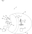
- Figure 1 shows system 1 for monitoring a danger area 2 of a machine 3, with at least one sensor 4 with at least one spatial monitoring area 5 for monitoring the danger area 2, and a control and evaluation unit 6, wherein the sensor 4 is designed to cyclically send 3D data of the monitoring area 5 to the control and evaluation unit 6, wherein the sensor 4 is further designed to generate at least one protection area 7 in the monitoring area 5, wherein the control and evaluation unit 6 is designed to compare the received 3D data of the monitoring area 5 with known position data of the machine 3 and to check for agreement, wherein the control and evaluation unit 6 is designed to localize objects 8 in the monitoring area 5 of the sensor 4 based on the 3D data and to determine their distance from a dangerous part 9 of the machine 3, wherein the control and evaluation unit 6 is designed to bridge the sensor 4 with the protection area 7 as long as there is a match the position data is present and the sensor 4 is not to be bypassed with the protection area 7 if the position data do not match and the sensor 4 is not to be bypassed with the protection area 7 if the distance from objects
- the machine 3 is a robot 12 and the danger zone 2 of the machine 3 is a danger zone 2 of the robot 12.
- the robot 12 can, for example, be a multi-axis robot 12, for example an assembly robot in a production line.
- machine 3 is a mobile machine or a fixed machine.
- a non-safe control and evaluation unit 6 or a control unit which is designed to compare 3D image data of the monitoring area 5 of the sensor 4 with the known position data of the robot 12 and to check for agreement.
- control and evaluation unit 6 is designed to localize other objects 8 in the field of view of the sensor 4 based on the 3D data of the sensor 4 and to determine their distance from the robot 12.
- these functions do not have to be carried out according to the specifications of functional safety.
- One or, for example, several sensors 4, in particular 3D sensors, are preferably safety-certified. These record 3D data of the monitoring area, protection area or danger area in real time and with synchronization information and deliver the data to the control and evaluation unit 6.
- the sensor 4 for example a safe 3D camera with integrated protection area function, is designed for the classic monitoring of the approach area around the robot 12.
- control and evaluation unit 6 it may be advantageous to use a secure controller for binary switching signals as the control and evaluation unit 6 in order to combine activation signals or bridging signals and the signal from the sensor 4.
- the basic idea is that the actual protection of the robot 12 is carried out using a simple protection area function of the sensor 4 or safety sensor. This means that if a person 13 is present as object 8 in the protection area 7, a shutdown signal is sent to the robot 12 or its control or its machine control. This protection is tried and tested and can be implemented with a high degree of reliability. In the following, it is referred to as the primary safety function.
- the other system components provide a function that, depending on the situation and the consistency and plausibility of the other information (3D data and machine position data), generates a signal to deactivate or bypass the primary safety function.
- the sensor(s) 4 or 3D sensors provide information or 3D data about the environment of the robot 12, which are used in two different ways.
- a check is carried out to determine whether the areas in which the robot's moving parts 9 should be located according to the robot control are also occupied by an object 8 in the 3D data or in the 3D image.
- This sub-function serves to check the plausibility and represents an effective check of the proper functioning of the sensor 4 and the robot control.
- stationary objects 8 in the monitoring area 5 can also be used in the same way for plausibility checks, for example the floor that is detected by the sensor 4. Since a specific expectation is checked here, in which the chance coincidence can be ruled out in the event of an error, and since this is a simple deactivation signal or muting signal, it is sufficient, in the simplest case, to use a non-safe control and evaluation unit 6 or a non-safe control system for the test.
- the 3D data also determines the distance between the person 12 or the object 8 and the dangerous part of the robot 13. If a predetermined distance threshold is undershot, the deactivation signal or bypass signal is deleted and the primary safety function switches off the robot 12.
- the shutdown signal from sensor 4 is already present and is suppressed by the deactivation signal or muting signal. As soon as the deactivation signal or muting signal is removed, the shutdown signal reaches robot 12 and robot 12 is stopped immediately.
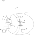
- An approach process can be summarized as follows: A person 13 approaches according to Figure 2 the robot 12 and enters the protection area 7. At this point in time, the distance of the person 13 is still large enough for the robot 12 to continue working. If necessary, the robot 12 is switched to a mode with a slowed movement sequence, for example. There is a match between the position data of the moving part 9 of the robot 12 from the machine control and the 3D data of the sensor 4, so that a deactivation signal or bridging signal has so far prevented the robot 12 from being switched off.
- the person 13 continues to approach and reaches a critical distance range.
- the sensor 4 or 3D sensor detects the critical approach and deletes the deactivation or bypass signal.
- the primary shutdown signal reaches the robot 12 and causes the robot 12 to stop.
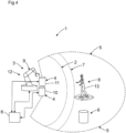
- a first sensor 10 designed as sensor 4 to cyclically supply 3D data of the monitoring area 5 to the control and evaluation unit 6 and a second sensor 11 designed as sensor 4 to generate a protection area 7.
- the first sensor 10 can be, for example, a 3D camera, a laser scanner with a protection area.
- the 3D camera can be, for example, a 3D time-of-flight camera or, for example, a 3D stereo camera.
- the second sensor 11 can be, for example, a 3D camera, a laser scanner with a protection area or a protection area.
- the 3D camera can be, for example, a 3D time-of-flight camera or, for example, a 3D stereo camera.
- control and evaluation unit 6 is designed to cause at least one part 9 of the robot 12 to perform an evasive movement or a slowdown if the distance of objects 8 to a dangerous part 9 of the robot falls below predefined second distance values.
- control and evaluation unit 6 is designed to redirect or brake the dangerous part 9 of the robot in order to maintain the productivity of the work process. This makes the control of the robot very flexible, since this part of the function is not part of the safety function.
- control and evaluation unit 6 is designed to compare the received 3D data of the monitoring area 5 with known position data of the environment and to check for consistency.
- a static environment is learned. This makes it easier to detect and track dynamically moving objects 8 such as people 13.
- control and evaluation unit 6 is designed to activate the protection area 7 if the dangerous part 9 of the robot 12 is in an unauthorized position.
Landscapes
- Engineering & Computer Science (AREA)
- Mechanical Engineering (AREA)
- Robotics (AREA)
- Physics & Mathematics (AREA)
- General Engineering & Computer Science (AREA)
- Multimedia (AREA)
- Optics & Photonics (AREA)
- General Physics & Mathematics (AREA)
- Automation & Control Theory (AREA)
- Manipulator (AREA)
Applications Claiming Priority (1)
| Application Number | Priority Date | Filing Date | Title |
|---|---|---|---|
| DE102023107215.3A DE102023107215A1 (de) | 2023-03-22 | 2023-03-22 | System und Verfahren zur Überwachung eines Gefahrenbereichs einer Maschine |
Publications (2)
| Publication Number | Publication Date |
|---|---|
| EP4435313A1 true EP4435313A1 (fr) | 2024-09-25 |
| EP4435313B1 EP4435313B1 (fr) | 2025-08-06 |
Family
ID=90123271
Family Applications (1)
| Application Number | Title | Priority Date | Filing Date |
|---|---|---|---|
| EP24160435.4A Active EP4435313B1 (fr) | 2023-03-22 | 2024-02-29 | Système et procédé de surveillance d'une zone dangereuse d'une machine |
Country Status (4)
| Country | Link |
|---|---|
| US (1) | US20240316778A1 (fr) |
| EP (1) | EP4435313B1 (fr) |
| CN (1) | CN118689140A (fr) |
| DE (1) | DE102023107215A1 (fr) |
Families Citing this family (2)
| Publication number | Priority date | Publication date | Assignee | Title |
|---|---|---|---|---|
| DE102023102951B4 (de) * | 2023-02-07 | 2025-03-13 | Sick Ag | Verfahren und berührungsloser Distanzsensor zum Absichern einer Maschine |
| DE102023107973B4 (de) * | 2023-03-29 | 2025-04-24 | Sick Ag | System und Verfahren zur Überwachung eines Gefahrenbereichs eines Roboters |
Citations (1)
| Publication number | Priority date | Publication date | Assignee | Title |
|---|---|---|---|---|
| WO2021025660A1 (fr) * | 2018-11-20 | 2021-02-11 | Transocean Sedco Forex Ventures Limited | Système et procédé de sécurité de personnes basé sur la proximité |
Family Cites Families (4)
| Publication number | Priority date | Publication date | Assignee | Title |
|---|---|---|---|---|
| DE102015113364B3 (de) * | 2015-08-13 | 2016-08-11 | Sick Ag | Sicherheitssystem und Verfahren zur Überwachung |
| DE102017101905B4 (de) * | 2017-01-31 | 2021-07-29 | Sick Ag | Überwachungseinrichtung |
| EP3859382B1 (fr) * | 2020-01-28 | 2022-08-03 | Sick Ag | Système de sécurité et procédé de localisation d'une personne ou d'un objet dans une zone de surveillance à l'aide d'un système de sécurité |
| US20240012383A1 (en) * | 2022-07-07 | 2024-01-11 | Datalogic Ip Tech S.R.L. | Clustering and detection system and method for safety monitoring in a collaborative workspace |
-
2023
- 2023-03-22 DE DE102023107215.3A patent/DE102023107215A1/de active Pending
-
2024
- 2024-02-29 CN CN202410229488.9A patent/CN118689140A/zh active Pending
- 2024-02-29 EP EP24160435.4A patent/EP4435313B1/fr active Active
- 2024-03-20 US US18/611,352 patent/US20240316778A1/en active Pending
Patent Citations (1)
| Publication number | Priority date | Publication date | Assignee | Title |
|---|---|---|---|---|
| WO2021025660A1 (fr) * | 2018-11-20 | 2021-02-11 | Transocean Sedco Forex Ventures Limited | Système et procédé de sécurité de personnes basé sur la proximité |
Also Published As
| Publication number | Publication date |
|---|---|
| EP4435313B1 (fr) | 2025-08-06 |
| US20240316778A1 (en) | 2024-09-26 |
| CN118689140A (zh) | 2024-09-24 |
| DE102023107215A1 (de) | 2024-09-26 |
Similar Documents
| Publication | Publication Date | Title |
|---|---|---|
| DE4411448C5 (de) | Verfahren und Vorrichtung zur Kontrolle eines vorgegebenen Überwachungsbereichs | |
| EP4435313B1 (fr) | Système et procédé de surveillance d'une zone dangereuse d'une machine | |
| EP3078985B1 (fr) | Capteur optoelectronique et procede de surveillance de transmission d'un disque frontal | |
| EP2386876A1 (fr) | Capteur de sécurité optoélectronique mesurant l'éloignement et procédé de surveillance d'une zone de surveillance | |
| EP2315052A1 (fr) | Scanner de sécurité | |
| EP3287809B1 (fr) | Procédé de fonctionnement d'un dispositif de baleyage et dispositif de baleyage | |
| DE102019132024A1 (de) | Sicherheitssystem | |
| EP3220164B1 (fr) | Procédé de fonctionnement d'un capteur écartométrique de surveillance et capteur écartométrique de surveillance | |
| EP3012663B1 (fr) | Systeme de securite destine a securiser l'environnement d'un objet | |
| EP2395372B1 (fr) | Scanner de sécurité | |
| EP2631668B1 (fr) | Système optique et procédé de contrôle de la capacité de fonctionnement d'un système optique | |
| DE19754220A1 (de) | Verfahren und Vorrichtung zur Erkennung einer bevorstehenden oder möglichen Kollision | |
| AT517784A1 (de) | Verfahren zur automatisierten Steuerung einer Maschinenkomponente | |
| DE202019106569U1 (de) | Sicherheitssystem | |
| EP4116733A1 (fr) | Caméra destinée à la capture des données d'image tridimensionnelle et procédé de vérification de la fonctionnalité d'une caméra | |
| DE202023101445U1 (de) | System zur Überwachung eines Gefahrenbereichs einer Maschine | |
| DE102017111367A1 (de) | Abstandsmesssystem, -verfahren und diese verwendendes Robotersystem | |
| DE102022130166A1 (de) | Sicherheitssystem und Verfahren mit einem Sicherheitssystem | |
| DE102022133248B4 (de) | System mit einem Sensor und Verfahren mit einem Sensor zur Überwachung mehrerer Schutzbereiche | |
| DE202022106978U1 (de) | System mit einem Sensor | |
| EP3825731A1 (fr) | Capteur optoélectronique de sécurité et procédé de détermination sécurisée de position propre | |
| EP3527332A1 (fr) | Dispositif capteur de sécurité et procédé de sécurisation d'une machine mobile | |
| EP3798668B1 (fr) | Capteur | |
| EP4431985B1 (fr) | Suivi d'objet sécurisé d'un objet | |
| DE102017119283A1 (de) | Sensorsystem |
Legal Events
| Date | Code | Title | Description |
|---|---|---|---|
| PUAI | Public reference made under article 153(3) epc to a published international application that has entered the european phase |
Free format text: ORIGINAL CODE: 0009012 |
|
| STAA | Information on the status of an ep patent application or granted ep patent |
Free format text: STATUS: THE APPLICATION HAS BEEN PUBLISHED |
|
| AK | Designated contracting states |
Kind code of ref document: A1 Designated state(s): AL AT BE BG CH CY CZ DE DK EE ES FI FR GB GR HR HU IE IS IT LI LT LU LV MC ME MK MT NL NO PL PT RO RS SE SI SK SM TR |
|
| STAA | Information on the status of an ep patent application or granted ep patent |
Free format text: STATUS: REQUEST FOR EXAMINATION WAS MADE |
|
| 17P | Request for examination filed |
Effective date: 20241219 |
|
| GRAP | Despatch of communication of intention to grant a patent |
Free format text: ORIGINAL CODE: EPIDOSNIGR1 |
|
| STAA | Information on the status of an ep patent application or granted ep patent |
Free format text: STATUS: GRANT OF PATENT IS INTENDED |
|
| GRAS | Grant fee paid |
Free format text: ORIGINAL CODE: EPIDOSNIGR3 |
|
| INTG | Intention to grant announced |
Effective date: 20250602 |
|
| GRAA | (expected) grant |
Free format text: ORIGINAL CODE: 0009210 |
|
| STAA | Information on the status of an ep patent application or granted ep patent |
Free format text: STATUS: THE PATENT HAS BEEN GRANTED |
|
| AK | Designated contracting states |
Kind code of ref document: B1 Designated state(s): AL AT BE BG CH CY CZ DE DK EE ES FI FR GB GR HR HU IE IS IT LI LT LU LV MC ME MK MT NL NO PL PT RO RS SE SI SK SM TR |
|
| REG | Reference to a national code |
Ref country code: GB Ref legal event code: FG4D Free format text: NOT ENGLISH |
|
| REG | Reference to a national code |
Ref country code: CH Ref legal event code: EP |
|
| REG | Reference to a national code |
Ref country code: DE Ref legal event code: R096 Ref document number: 502024000135 Country of ref document: DE |
|
| REG | Reference to a national code |
Ref country code: IE Ref legal event code: FG4D Free format text: LANGUAGE OF EP DOCUMENT: GERMAN |
|
| REG | Reference to a national code |
Ref country code: NL Ref legal event code: MP Effective date: 20250806 |
|
| PG25 | Lapsed in a contracting state [announced via postgrant information from national office to epo] |
Ref country code: IS Free format text: LAPSE BECAUSE OF FAILURE TO SUBMIT A TRANSLATION OF THE DESCRIPTION OR TO PAY THE FEE WITHIN THE PRESCRIBED TIME-LIMIT Effective date: 20251206 |
|
| PG25 | Lapsed in a contracting state [announced via postgrant information from national office to epo] |
Ref country code: NO Free format text: LAPSE BECAUSE OF FAILURE TO SUBMIT A TRANSLATION OF THE DESCRIPTION OR TO PAY THE FEE WITHIN THE PRESCRIBED TIME-LIMIT Effective date: 20251106 |
|
| REG | Reference to a national code |
Ref country code: LT Ref legal event code: MG9D |
|
| PG25 | Lapsed in a contracting state [announced via postgrant information from national office to epo] |
Ref country code: PT Free format text: LAPSE BECAUSE OF FAILURE TO SUBMIT A TRANSLATION OF THE DESCRIPTION OR TO PAY THE FEE WITHIN THE PRESCRIBED TIME-LIMIT Effective date: 20251209 |
|
| PG25 | Lapsed in a contracting state [announced via postgrant information from national office to epo] |
Ref country code: FI Free format text: LAPSE BECAUSE OF FAILURE TO SUBMIT A TRANSLATION OF THE DESCRIPTION OR TO PAY THE FEE WITHIN THE PRESCRIBED TIME-LIMIT Effective date: 20250806 |
|
| PG25 | Lapsed in a contracting state [announced via postgrant information from national office to epo] |
Ref country code: HR Free format text: LAPSE BECAUSE OF FAILURE TO SUBMIT A TRANSLATION OF THE DESCRIPTION OR TO PAY THE FEE WITHIN THE PRESCRIBED TIME-LIMIT Effective date: 20250806 Ref country code: NL Free format text: LAPSE BECAUSE OF FAILURE TO SUBMIT A TRANSLATION OF THE DESCRIPTION OR TO PAY THE FEE WITHIN THE PRESCRIBED TIME-LIMIT Effective date: 20250806 |
|
| PG25 | Lapsed in a contracting state [announced via postgrant information from national office to epo] |
Ref country code: GR Free format text: LAPSE BECAUSE OF FAILURE TO SUBMIT A TRANSLATION OF THE DESCRIPTION OR TO PAY THE FEE WITHIN THE PRESCRIBED TIME-LIMIT Effective date: 20251107 |
|
| PG25 | Lapsed in a contracting state [announced via postgrant information from national office to epo] |
Ref country code: SE Free format text: LAPSE BECAUSE OF FAILURE TO SUBMIT A TRANSLATION OF THE DESCRIPTION OR TO PAY THE FEE WITHIN THE PRESCRIBED TIME-LIMIT Effective date: 20250806 |
|
| PG25 | Lapsed in a contracting state [announced via postgrant information from national office to epo] |
Ref country code: LV Free format text: LAPSE BECAUSE OF FAILURE TO SUBMIT A TRANSLATION OF THE DESCRIPTION OR TO PAY THE FEE WITHIN THE PRESCRIBED TIME-LIMIT Effective date: 20250806 |
|
| PG25 | Lapsed in a contracting state [announced via postgrant information from national office to epo] |
Ref country code: PL Free format text: LAPSE BECAUSE OF FAILURE TO SUBMIT A TRANSLATION OF THE DESCRIPTION OR TO PAY THE FEE WITHIN THE PRESCRIBED TIME-LIMIT Effective date: 20250806 Ref country code: BG Free format text: LAPSE BECAUSE OF FAILURE TO SUBMIT A TRANSLATION OF THE DESCRIPTION OR TO PAY THE FEE WITHIN THE PRESCRIBED TIME-LIMIT Effective date: 20250806 |
|
| PG25 | Lapsed in a contracting state [announced via postgrant information from national office to epo] |
Ref country code: RS Free format text: LAPSE BECAUSE OF FAILURE TO SUBMIT A TRANSLATION OF THE DESCRIPTION OR TO PAY THE FEE WITHIN THE PRESCRIBED TIME-LIMIT Effective date: 20251106 |
|
| PG25 | Lapsed in a contracting state [announced via postgrant information from national office to epo] |
Ref country code: ES Free format text: LAPSE BECAUSE OF FAILURE TO SUBMIT A TRANSLATION OF THE DESCRIPTION OR TO PAY THE FEE WITHIN THE PRESCRIBED TIME-LIMIT Effective date: 20250806 |
|
| PG25 | Lapsed in a contracting state [announced via postgrant information from national office to epo] |
Ref country code: SM Free format text: LAPSE BECAUSE OF FAILURE TO SUBMIT A TRANSLATION OF THE DESCRIPTION OR TO PAY THE FEE WITHIN THE PRESCRIBED TIME-LIMIT Effective date: 20250806 |
|
| PG25 | Lapsed in a contracting state [announced via postgrant information from national office to epo] |
Ref country code: DK Free format text: LAPSE BECAUSE OF FAILURE TO SUBMIT A TRANSLATION OF THE DESCRIPTION OR TO PAY THE FEE WITHIN THE PRESCRIBED TIME-LIMIT Effective date: 20250806 |
|
| PGFP | Annual fee paid to national office [announced via postgrant information from national office to epo] |
Ref country code: DE Payment date: 20260217 Year of fee payment: 3 |
|
| PG25 | Lapsed in a contracting state [announced via postgrant information from national office to epo] |
Ref country code: IT Free format text: LAPSE BECAUSE OF FAILURE TO SUBMIT A TRANSLATION OF THE DESCRIPTION OR TO PAY THE FEE WITHIN THE PRESCRIBED TIME-LIMIT Effective date: 20250806 |
|
| PGFP | Annual fee paid to national office [announced via postgrant information from national office to epo] |
Ref country code: FR Payment date: 20260223 Year of fee payment: 3 |
|
| PG25 | Lapsed in a contracting state [announced via postgrant information from national office to epo] |
Ref country code: CZ Free format text: LAPSE BECAUSE OF FAILURE TO SUBMIT A TRANSLATION OF THE DESCRIPTION OR TO PAY THE FEE WITHIN THE PRESCRIBED TIME-LIMIT Effective date: 20250806 |
|
| PG25 | Lapsed in a contracting state [announced via postgrant information from national office to epo] |
Ref country code: EE Free format text: LAPSE BECAUSE OF FAILURE TO SUBMIT A TRANSLATION OF THE DESCRIPTION OR TO PAY THE FEE WITHIN THE PRESCRIBED TIME-LIMIT Effective date: 20250806 Ref country code: SK Free format text: LAPSE BECAUSE OF FAILURE TO SUBMIT A TRANSLATION OF THE DESCRIPTION OR TO PAY THE FEE WITHIN THE PRESCRIBED TIME-LIMIT Effective date: 20250806 |