EP4435442A1 - Appareil de contrôle et procédé de contrôle d'un câble haute ou moyenne tension - Google Patents
Appareil de contrôle et procédé de contrôle d'un câble haute ou moyenne tension Download PDFInfo
- Publication number
- EP4435442A1 EP4435442A1 EP24163197.7A EP24163197A EP4435442A1 EP 4435442 A1 EP4435442 A1 EP 4435442A1 EP 24163197 A EP24163197 A EP 24163197A EP 4435442 A1 EP4435442 A1 EP 4435442A1
- Authority
- EP
- European Patent Office
- Prior art keywords
- voltage
- frequency
- test
- signal
- test device
- Prior art date
- Legal status (The legal status is an assumption and is not a legal conclusion. Google has not performed a legal analysis and makes no representation as to the accuracy of the status listed.)
- Granted
Links
Images



Classifications
-
- G—PHYSICS
- G01—MEASURING; TESTING
- G01R—MEASURING ELECTRIC VARIABLES; MEASURING MAGNETIC VARIABLES
- G01R31/00—Arrangements for testing electric properties; Arrangements for locating electric faults; Arrangements for electrical testing characterised by what is being tested not provided for elsewhere
- G01R31/08—Locating faults in cables, transmission lines, or networks
- G01R31/081—Locating faults in cables, transmission lines, or networks according to type of conductors
- G01R31/083—Locating faults in cables, transmission lines, or networks according to type of conductors in cables, e.g. underground
-
- G—PHYSICS
- G01—MEASURING; TESTING
- G01R—MEASURING ELECTRIC VARIABLES; MEASURING MAGNETIC VARIABLES
- G01R31/00—Arrangements for testing electric properties; Arrangements for locating electric faults; Arrangements for electrical testing characterised by what is being tested not provided for elsewhere
- G01R31/12—Testing dielectric strength or breakdown voltage ; Testing or monitoring effectiveness or level of insulation, e.g. of a cable or of an apparatus, for example using partial discharge measurements; Electrostatic testing
- G01R31/14—Circuits therefor, e.g. for generating test voltages, sensing circuits
-
- G—PHYSICS
- G01—MEASURING; TESTING
- G01R—MEASURING ELECTRIC VARIABLES; MEASURING MAGNETIC VARIABLES
- G01R31/00—Arrangements for testing electric properties; Arrangements for locating electric faults; Arrangements for electrical testing characterised by what is being tested not provided for elsewhere
- G01R31/12—Testing dielectric strength or breakdown voltage ; Testing or monitoring effectiveness or level of insulation, e.g. of a cable or of an apparatus, for example using partial discharge measurements; Electrostatic testing
- G01R31/1227—Testing dielectric strength or breakdown voltage ; Testing or monitoring effectiveness or level of insulation, e.g. of a cable or of an apparatus, for example using partial discharge measurements; Electrostatic testing of components, parts or materials
- G01R31/1263—Testing dielectric strength or breakdown voltage ; Testing or monitoring effectiveness or level of insulation, e.g. of a cable or of an apparatus, for example using partial discharge measurements; Electrostatic testing of components, parts or materials of solid or fluid materials, e.g. insulation films, bulk material; of semiconductors or LV electronic components or parts; of cable, line or wire insulation
- G01R31/1272—Testing dielectric strength or breakdown voltage ; Testing or monitoring effectiveness or level of insulation, e.g. of a cable or of an apparatus, for example using partial discharge measurements; Electrostatic testing of components, parts or materials of solid or fluid materials, e.g. insulation films, bulk material; of semiconductors or LV electronic components or parts; of cable, line or wire insulation of cable, line or wire insulation, e.g. using partial discharge measurements
-
- G—PHYSICS
- G01—MEASURING; TESTING
- G01R—MEASURING ELECTRIC VARIABLES; MEASURING MAGNETIC VARIABLES
- G01R31/00—Arrangements for testing electric properties; Arrangements for locating electric faults; Arrangements for electrical testing characterised by what is being tested not provided for elsewhere
- G01R31/50—Testing of electric apparatus, lines, cables or components for short-circuits, continuity, leakage current or incorrect line connections
- G01R31/52—Testing for short-circuits, leakage current or ground faults
-
- G—PHYSICS
- G01—MEASURING; TESTING
- G01R—MEASURING ELECTRIC VARIABLES; MEASURING MAGNETIC VARIABLES
- G01R31/00—Arrangements for testing electric properties; Arrangements for locating electric faults; Arrangements for electrical testing characterised by what is being tested not provided for elsewhere
- G01R31/50—Testing of electric apparatus, lines, cables or components for short-circuits, continuity, leakage current or incorrect line connections
- G01R31/58—Testing of lines, cables or conductors
Definitions
- the present invention relates to a test device for testing a high-voltage or medium-voltage cable, in particular for testing insulation in coaxial cables for power/energy distribution in electrical supply networks using VLF test methods.
- the invention also relates to a method for testing, in particular for diagnosing and locating, a high-voltage or medium-voltage cable fault.
- the testing of high or medium voltage cables includes testing for the purpose of determining any existing defects or previous damage (here also referred to as a defect in a high or medium voltage cable).
- Defects can, for example, form in the insulation of a high voltage cable.
- a defect can be a defect in the cable insulation that causes a breakthrough.
- a defect can also be a defect in the cable insulation that does not yet cause a breakthrough or does cause a breakthrough. These can be so-called water trees or electrical trees.
- mobile VLF test devices enable a test object to be tested using a test voltage, for example in the range of 20 kVpeak to 120 kVpeak (generally not limited), which is generated with a high-precision voltage curve at a frequency in the range of 0.01 Hz to 1 Hz, the so-called Very Low Frequency (VLF), and is applied to the test object as a power cable on the conductor opposite protective earth.
- VLF-based test methods are well known and defined, for example, in IEEE 400.2.
- VLF test equipment For voltage generation, VLF test equipment includes special VLF test generators (also referred to as VLF high voltage sources).
- VLF test generator can preferably include two high voltage sources (cascaded transformers) and an output amplifier (in the form of current sources) which together generate a very low-noise sinusoidal output voltage (the "test voltage"). Circuit arrangements for generating such test voltages are for example in the EN 10 2012 024 560 B3 the applicant or the DE 195 13 441 A1 revealed.
- a loss factor can be determined in a so-called tangent delta measurement.
- the current through the defect can be recorded - despite the test object being connected to protective earth - i.e. without the test object having to be separated from protective earth.
- a current recording element e.g. resistor as a current shunt
- the current can be recorded at a collection point in the VLF test generator, through which the current flows from the test object back to the high-voltage cascade (see e.g.
- test current is recorded, for example, with a resistance in the range of 0.01 k ⁇ to 1 k ⁇ in a frequency range up to usually 5 kHz (not more than 50 kHz) and is used to determine the power loss (resistive leakage current) via the phase shift.
- various so-called fault location methods are known for locating a defect in a test object. These methods are based on the determination that there is a fault in a power cable, which was detected, for example, by a voltage breakdown between the conductor and the shield during operation or during a test. To locate the fault, a voltage in the range of, for example, 8 kV to 40 kV is again applied to the test object using a high-voltage generator until there is another breakdown in the high-voltage cable.
- the devices are structurally limited in terms of the energy they can provide. Usually, energies in the 1000 kJ range (current pulse based on, for example, 10 ⁇ F to 20 ⁇ F in the kA range) can be provided.
- the current pulse triggers an oscillation (transient wave) in the test object, the course of which is recorded.
- the oscillation in the test object can, for example, be B. by means of a capacitive voltage divider, which is connected externally (i.e. on the high-voltage side) to the test object for voltage measurement in addition to the high-voltage generator.
- it can be detected by means of an inductance, which is provided externally (i.e. on the high-voltage side) on a supply line for measuring the circulating current. The distance to the fault is determined from the frequency of the oscillation.
- the inventors have recognized the disadvantages of these fault location methods based on externally mounted devices.
- the mounting for a correct current measurement is inaccurate and limited in sensitivity.
- One aspect of this disclosure is based on the object of specifying a device and a method for fault pre-location that is easy to carry out, for example, in conjunction with a cable testing process.
- advantages of fault location that can be carried out during the test have been recognized, as a result of which the growth of the fault can be reduced or avoided if fault pre-location can be completed before a breakdown.
- Such a diagnosis without forced breakdown can partially preserve the insulation of a partially defective cable, delay the replacement of the defective cable and, in particular, save time if testing and diagnosis can be carried out simultaneously.
- a further aspect of this disclosure is based on the object of providing a compact and cost-effective design of a test device for testing a high-voltage or medium-voltage cable, which enables safe, simple and cost-effective test procedures to be carried out.
- At least one of these objects is achieved by a testing device for testing a high-voltage or medium-voltage cable according to claim 1 and by a method according to claim 11 or 12. Further developments are specified in the subclaims.
- a test device for testing a high-voltage or medium-voltage cable in particular by means of a very low frequency (VLF) test method, has a circuit arrangement.
- This comprises a test voltage generation unit, which comprises a low-voltage-side ground input and a high-voltage-side output and is designed to provide a variable test voltage at the high-voltage-side output, a power connection for connecting the test voltage generation unit to a Supply voltage source, a test object connection for connecting the high-voltage side output to a conductor of the high-voltage or medium-voltage cable, in particular via a measuring connection cable, and a protective earth connection for connecting to protective earth.
- VLF very low frequency
- test device comprises an evaluation electronics which is connected to the low-frequency signal tap for receiving the low-frequency diagnostic signal and is designed for a VLF phase rotation measurement and which is connected to the high-frequency signal tap for receiving the high-frequency pre-location signal and is designed for a fault distance evaluation.
- the circuit arrangement can be set up to use the variable test voltage to simultaneously generate the low-frequency diagnostic signal for an insulation test of the high-voltage or medium-voltage cable via the VLF phase rotation measurement and the high-frequency pre-location signal for fault pre-location via the measurement of transient high-frequency oscillations.
- the low-voltage-side earthing input can only be connected to protective earth via the connecting conductor.
- the high-frequency signal tap can comprise an electrical and/or magnetic coupling with the connecting conductor and the coupling can be designed to detect the pre-location signal with frequencies in the range of 20 kHz to 2 MHz with a sampling rate with frequencies in the range of 1 MHz to several 100 MHz.
- the coupling can be designed as an inductive coupling, in particular via a coil such as a Rogowski coil or (air) coil with or without an inductive core.
- the high-frequency signal tap can be designed to continuously detect a high-frequency current oscillation in the connecting conductor.
- the high-frequency current oscillation can be particularly a breakdown of the insulation in the high- or medium-voltage cable or a high-frequency current oscillation associated with an impending breakdown may be detectable.
- the test voltage generation unit can generate the test voltage for a tangent delta measurement.
- the low-frequency signal tap can be designed to detect an instantaneous value of a current in the connecting conductor.
- it can comprise an impedance in the connecting conductor, in particular a parallel circuit of a resistor and a capacitor.
- the evaluation electronics can be set up to determine a loss factor associated with the high-voltage or medium-voltage cable from the diagnostic signal and is designed in particular to detect low frequencies of the diagnostic signal in the range from 0.01 Hz to 1 Hz with a sampling rate with frequencies in the range from 500 Hz to 10 kHz.
- the evaluation electronics can comprise at least one analog and/or digital signal processing unit and/or a processor and/or a buffer memory.
- the test device may further comprise a control unit with a memory and a display, wherein the control unit is connected to the evaluation electronics and is configured to store an error distance variable in the memory, output it on the display and/or use an error distance variable as a control parameter for controlling the test device, in particular for terminating a VLF test.
- a control unit with a memory and a display
- the control unit is connected to the evaluation electronics and is configured to store an error distance variable in the memory, output it on the display and/or use an error distance variable as a control parameter for controlling the test device, in particular for terminating a VLF test.
- the test device may further comprise a housing in which the circuit arrangement and the evaluation electronics and optionally a control unit are arranged.
- the processor may apply a discrete Fourier transform to the measurement data set to identify the plurality of dominant oscillations and generate a transformed measurement data set in the frequency domain, detect at least one dominant oscillation frequency, transform the at least one dominant oscillation frequency back to the time domain, and derive it as at least one dominant oscillation for correlating with the cached measurement data set.
- the processor may apply a continuous wavelet transform to the measurement data set to identify the plurality of dominant oscillations, detect at least one dominant characteristic in the spectrum, transfer the at least one dominant characteristic to the time domain, and derive it as at least one dominant oscillation for correlating with the cached measurement data set.
- the high-frequency pre-location signal can be evaluated with regard to a fault distance in such a way that a fault distance value is calculated for a fundamental oscillation whose plausibility is above a threshold value.
- parameters associated with the fundamental oscillation such as oscillation frequency, periodicity and quality information and/or the fault distance value can be stored in a memory, saved in a measurement protocol, output on a display and/or fed to a control of the test device as a control parameter, in particular for terminating a VLF test.
- a VLF test device which, in addition to the tangent delta measurement, allows an integrated fault pre-location measurement, which is carried out in the form of continuous sampling of RF data in the frequency range of e.g. 0.01 MHz to 1 MHz (corresponding to fault distances in the range of e.g. 10 km to 40 m) with sampling rates of up to 2 MHz and more (e.g. 4 MHz) and does not require prior breakdown detection.
- a target core area for fault pre-location is usually in the range of 100 m to 10 km. Due to the different measurement signals, the bandwidth required for the fault pre-location measurement is spectrally decoupled from the tangent delta measurement. It is carried out in an independent signal tap and is subject to a specific signal evaluation that does not require breakdown detection.
- the fault prelocation measurement can be carried out at a low voltage potential (preferably close to protective earth potential) - in the VLF test device.
- a low voltage potential preferably close to protective earth potential
- no spatially voluminous expansion of a measuring device is necessary.
- Fault location using the state-of-the-art external pre-location method may employ high capacitances discharged into the cable to ignite a fault location and initiate oscillation.
- the discharge of such high energies may further damage or destroy the fault location and adjacent areas in addition to the existing fault.
- the voltage limitation is limited by large components; for example, fault location in the state of the art is usually limited to maximum voltages of e.g. 32 kV or 40 kV, since otherwise the capacitors for discharging to the cable become disproportionately large.
- the design of the VLF-HV generator is such that the current necessarily oscillates both positively and negatively at the current collection point; therefore, the current can be inductively detected over a very wide current range without the need for a control adjustment with multiple breakdowns, since a magnetic saturation effect can be largely prevented.
- the new approach described here implements a method that makes it possible to detect superimposed oscillations in a signal, such as those that can occur in the case of a short spark or multiple breakdowns. This increases the quality of the evaluation.
- a VLF test device can be used to locate a fault in a test object.
- data can be collected and evaluated to determine the fault distance in parallel to the tangent-delta test and diagnosis of a possible fault in the test object.
- an evaluation for determining the fault distance can be carried out at the same time as the tangent delta test.
- a high-frequency oscillation is recorded in the form of a high-frequency pre-location signal, whereby the latter signal can be triggered in connection with a fault, in particular when a breakdown occurs. If a "correct" oscillation frequency can be assigned to the oscillation, the associated periodicity is proportional to the distance of the fault along the cable.
- a signal of the oscillation can be recorded, for example, inductively/magnetically using a coil (e.g. Rogowski or air coil with or without an inductive core, example inductances from 0.1 ⁇ H to 10 ⁇ H, in particular 1 ⁇ H to 6 ⁇ H, and a bandwidth of several MHz) or alternatively in voltage via a current shunt. Since the current collection point is only present internally in the VLF-HV generator, this location offers the possibility of using the measuring current for tangent delta diagnosis as well as for fault location.
- a coil e.g. Rogowski or air coil with or without an inductive core, example inductances from 0.1 ⁇ H to 10 ⁇ H, in particular 1 ⁇ H to 6 ⁇ H, and a bandwidth of several MHz
- the invention is therefore also based on the knowledge regarding the tapping of the vibration signal.
- the vibration signal cannot simply be tapped, for example, from the high-voltage connection cable, since the current can circulate via several protective earth-related connections, so that if it is tapped there, the resolution may not be sufficient or correspondingly higher pulse currents would have to be generated in order to achieve a measurable vibration signal.
- the fault pre-location concepts described here are particularly unique in that the clever positioning of the vibration detection in the current measurement path of a VLF-HV generator (i.e. at the current collection point) makes it possible to directly determine the distance to the fault location in the event of a breakdown during the test.
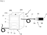
- Fig.1 shows a schematic representation of a portable test device 1 for testing a test object 3, e.g. a high or medium voltage cable such as a coaxial cable, according to the inventive concept.
- the test device 1 comprises a circuit arrangement 5, essentially a VLF test voltage generation unit 7 for generating a suitable (VLF) test voltage, and (measurement and) evaluation electronics 9 coupled to the circuit arrangement 5 and integrated into the test device.
- the evaluation electronics 9 are set up both for a tangent delta measurement (tangent delta measurement unit 11) and for fault pre-location (fault pre-location unit 13).
- the hardware (processing unit) underlying the evaluation electronics 9 has, for example, digital processor systems with microprocessor circuits having data inputs and control outputs, which are operated according to computer-readable instructions stored on a computer-readable medium.
- the evaluation electronics 9 comprise high computing power for real-time analysis of the continuously acquired and evaluated data sets as well as long-term (non-volatile) memory for storing the program instructions as well as very fast short-term (volatile) memory for storing acquired data and evaluation results during (or resulting from) the data acquisition and data processing of low and/or high frequency signals described below.
- the test device 1 is supplied with energy via, for example, the power grid (generally a supply voltage source) (power connection 15).
- a conductor 3A of the test object 3 is connected to the test device 1 via a (HV) connection cable 17 (with exemplary lengths of 5 m to 15 m).
- a shield 3B of the test object 3 as well as the circuit arrangement 5, as explained in more detail below, are connected to protective earth 19, whereby the power connection 15 can also carry a protective earth 19 (see also Fig. 2 ).
- an insulation 3C to be tested.
- the circuit arrangement 5 is arranged in a housing 21 of the test device 1 and can comprise electronic components such as signal processing with operational amplifiers, at least one integrator, a sample and hold element, at least one analog-digital converter for digitization for further processing in a processor which has at least one memory for storing sampling data (measurement data).
- the circuit arrangement 5 can also be connected to or (partially) integrated into a control 23 of the test device 1 provided in the test device 1 or completely or partially outside the test device 1. This in turn generates a test voltage together with the high-voltage sources contained in the circuit arrangement 5 by providing the power for the current sources required to regulate the test voltage, for example via a transformer and downstream cascade multiplier.
- an operating display 25A (display) for displaying the acquired test data and at least one operating element 25B for setting a measurement parameter are provided (schematically shown in Fig.1
- the operating display 25A and the operating element 25B form, for example, a user interface of the control 23.
- Fig. 2 shows an exemplary circuit diagram for the circuit arrangement 5 of the Fig.1 illustrated test device 1 with the test object 3 connected via the connection cable 17.
- the test voltage generation unit 7 comprises, for example, two high-voltage sources 27 which are supplied with energy via the power connection 15 and are set up to provide a positive (+) or negative (-) high voltage of variable amplitude at their respective outputs, for example by operating a modulation with a multiple of the mains frequency.
- a high-voltage switch arrangement 29 is provided, which is acted upon by means of a control 31 for the defined charging and discharging of the test object 3, which represents a certain capacitive load.
- the control 31 is set up to ensure a, preferably sinusoidal, voltage curve on the test object 3.
- the high-voltage switch arrangement 29 comprises, for example, two semiconductor switch cascades 29A, each with an amplifier 29B, which are acted upon by the control 31. Furthermore, the high-voltage sources 27 are controlled by the control 23 using a clock signal generator T, so that the two high-voltage sources 27 can each provide a test voltage that is synchronized using the clock signal generator T, can be defined in terms of curve shape and amplitude, is advantageously edge-free and in particular sinusoidal, and is not influenced by the control 31.
- the test voltage generation unit 7 comprises a low-voltage-side grounding input 7A and a high-voltage-side output 7B.
- the output 7B is electrically connected to a test object connection 33, to which the conductor 3A of the test object 3 is electrically connected for testing.
- the test voltage generation unit 7 is grounded at the low-voltage-side grounding input 7A via a protective earth connection 35 (internal earth potential during operation).
- the shield 3B (sheath) of the test object 3 is also connected to Protective earth is connected so that the shield 3B and the VLF test device 1, in particular the test voltage generation unit 7, are on a common protective earth.
- the shield 3B is at earth potential (protective earth 19) at the beginning and at the end.
- an electrical circuit can form through which a measuring current can flow and which extends from the test voltage generation unit 7 via the test object 3, in particular the defect 37, and through the protective earth connection 35 via the earth input 7A back to the test voltage generation unit 7.
- the measuring current is accessible for measurement within the test device 1 and in a low-voltage environment via a connecting conductor 39, which electrically connects the low-voltage-side ground input 7A to the protective earth connection 35 (internal earth potential during operation).
- the connecting conductor 39 thus represents a current collection point for measuring the measuring current and is used for a low-frequency signal tap 41, for example via an impedance 41A, to generate a diagnostic signal.
- the diagnostic signal is used as part of analog and/or digital signal processing in the tangent-delta measuring unit 11 to determine the phase and thus the power loss.
- a high-frequency signal tap 43 for example inductively via a coil 43A, is positioned in the low-voltage environment of the connecting conductor 39 to generate a high-frequency pre-location signal.
- the high-frequency signal tap 43 can be positioned before or after the low-frequency signal tap 41 along the connecting conductor 39.
- the background is that in the event of a breakdown at the defect 37 or during the formation of a breakdown or in the event of a correspondingly high-energy partial discharge, a high-frequency oscillation is formed, the frequency of which depends on a position of the defect 37 in the test object, in particular on a distance D of the defect 37 to the test object connection 33 (understood by the person skilled in the art as given by a distance size of the fault/defect - fault distance size).
- Information about this high-frequency oscillation can be obtained via the high-frequency pre-location signal in the evaluation electronics 9, in particular with analog and/or digital signal processing in the fault pre-location unit 13.
- the information can be stored in the Control of test device 1 or output/saved to a tester as part of a measurement protocol.
- Information regarding fault pre-location can be obtained continuously during the tangent delta measurement, since the high-frequency pre-location signal can be continuously recorded and evaluated.
- the evaluation includes, for example, a plausibility check for reasonable fault distances by obtaining fundamental frequencies from the high-frequency pre-location signal, which are then compared with the cable length.
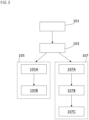
- Fig.3 uses a flow chart to illustrate the process of testing insulation in, for example, coaxial cables for power/energy distribution in electrical supply networks.
- information on insulation is obtained for testing and diagnostic measurements using a phase rotation measurement (tangent delta measurement) and a measurement of fast (high-frequency), transient oscillations during or before a breakdown of the cable insulation and is evaluated in particular for distance calculation (pre-location).
- the conductor 3A of the test object 3 is connected to a test object connection 33 of the test device 1 (for example via the connection cable 17) and the shield 3B of the test object 3 is in the mounted state of the test object or is connected to protective earth 19 (step 101).
- the test voltage here a very low frequency (VLF) test voltage
- VLF very low frequency
- the test voltage varies sinusoidally at a frequency of 0.01 Hz to 1 Hz with a voltage amplitude typically in the range of 20 kVpeak to 120 kVpeak, in particular from 40 kVpeak to 100 kVpeak.
- the clock signal generator T provides a time base for clocking the high voltage sources 27, so that the sinusoidal test voltage can be generated by semiconductor switch cascades 29A (as current sources) via the control 23 at the output 7B of the test voltage generation unit 7.
- the voltage applied to the test object 3 subjects the insulation 3C of the test object 3, arranged between conductor 3A and shield 3B, to a defined field strength and enables the insulation 3C to be tested.
- a regulated current flows from the semiconductor switch cascades 29A (as current sources) through the test object 3, which flows via the protective earth, in particular the protective earth connection 35, back to the Test voltage generation unit 7 (the high voltage sources 27) forms a closed circuit.
- an instantaneous value of the current, a course of the current and its phase position are determined via an impedance (as an example of a low-frequency signal tap), preferably a parallel circuit of resistor and capacitor, and by means of signal processing carried out in the evaluation electronics 9 and forwarded to the control unit.
- a low-frequency diagnostic signal associated with the measuring current is generated for a phase rotation measurement with a low-frequency signal tap at the current collection point (step 105A) and evaluated by the evaluation unit with regard to the phase position and the loss factor (step 105B).
- the determination of the loss factor and the underlying arrangement are preferably designed to detect and evaluate low frequencies associated with the measuring current in the range of the diagnostic signal 0.01 Hz to 1 Hz. For example, a digital sampling rate is available for frequencies in the range of 500 Hz to 10 kHz.
- step 107 For fault pre-location (step 107), high-frequency oscillations are measured (step 107A) via an inductive coupling (as an example of a high-frequency signal tap) and a high-frequency pre-location signal is generated (step 107B) and evaluated with regard to a fault distance (step 107C) using signal processing carried out in the evaluation electronics 9.
- currents are recorded continuously and thus also in the event of a possible breakdown of the insulation 3C in the test object 3 or even before the breakdown and are continuously evaluated for plausibility in accordance with the known parameters of the test object 3 (such as the length).
- the inductive coupling is preferably designed for frequencies assigned to the measuring current during breakdown (transient wave, oscillation) in the range from 20 kHz to 2 MHz.
- a digital sampling rate is for frequencies in the range from 1 MHz to several 100 MHz.
- the signal processing in step 107C is used to detect traveling waves.
- the signal processing involves a continuous sampling of the fault pre-location signal, optionally with a window of the pre-location signal (step 109 - "permanent sampling and framing") and an (intermediate) storage of the continuously resulting measurement data in, for example, a cyclic memory/ring buffer (step 111 - "storing in cyclic buffer”).
- the windowing can be used, for example, to prepare a partial area of the cyclically recorded signal as a section for further signal processing.
- the signal processing includes an identification step (step 113 - "identifying fundamental waves"), in which one or more dominant oscillations and their parameters (such as frequency, phase position and amplitude, as well as amplitude ratio) can be determined from the signal.
- the identification step can provide oscillation data in a time domain, for example for a back-transformed time domain section, which are used for subsequent evaluation calculations.
- a correlation of identified dominant vibrations with the original measurement data can be carried out (step 115 - "performing correlation of fundamentals") in order to select or confirm the most suitable vibration (or several suitable vibrations) and preferably to identify the vibration that best fits the measurement data.
- a correlation represents a measure of the agreement of the measurement signal with the identified vibration.
- an identified dominant oscillation can be checked for plausibility with regard to the test object (step 117 - "evaluating parameters of fundamentals"). If the plausibility check is successful (e.g. the determined plausibility is above a threshold value), this dominant oscillation represents a fundamental oscillation that is due to a defect.
- the parameters determined for the oscillation can be stored by the control unit in a measurement protocol (step 119B) and/or displayed on the display (step 119C).
- Fig.5 shows a schematic flow chart of exemplary implementations for fundamental oscillation identification (step 113 in Fig.4 ).
- the fundamental oscillation identification starts from step 109, in which, for example, measurement data is continuously digitally recorded in the cyclic memory in a target time window that corresponds to the monitored cable length, whereby windowing can be carried out for signal processing.
- the permanent evaluation can, in a first variant (in the time domain), continuously detect zero crossings and/or peak values for the dominant oscillation in the Determine the measurement data stored in the cyclic memory (step 121) and note their positions in the memory (and/or alternatively the associated difference values). These can be forwarded and processed as a running index stack, for example. For example, the underlying frequencies of one or more dominant oscillations (“fundamentals”) can be identified from the index stack using the given time base (sampling rate) (step 123).
- the identified frequencies can be checked for the best possible approximation using the cyclic memory and the original measurement data via a correlation. If a suitable fundamental frequency is found and this corresponds to the limiting parameters of the test object, which are given due to the expected or suitable cable length, the identified fundamental frequency can be added to a measurement report.
- the permanent evaluation can, in a second variant (in the frequency domain) - starting from step 109 - transform the windowed signal into a frequency spectrum based on a sinusoidal oscillation using a discrete Fourier transformation (step 131 - "discrete Fourier transformation into frequency domain"). In the frequency domain, a weighting of possible dominant sinusoidal amplitudes results.
- a selection of dominant (sinusoidal) oscillations can be made based on an amplitude evaluation (step 133 - "identifying one or more dominant frequencies in frequency domain”).
- the identified frequencies can be transformed back (step 135 - "inverse Fourier transformation") and superimposed on the measurement signal in the time domain as a dominant oscillation (transient).
- the identified frequencies/dominant oscillations can be checked for the best possible approximation using the measurement data stored in the cyclic memory via a correlation (steps 115 and 117 in Fig.4 ). If a suitable fundamental oscillation is found and this corresponds to the limiting parameters of the test object, which are given due to the expected or suitable cable length, the identified fundamental oscillation can be added to the measurement report.
- the permanent evaluation can, in a third variant (in the "spectral range") - starting from step 109 - transform the windowed signal into a spectrum based on expected (typical) and predefined waveforms using a continuous wavelet transformation (step 141 - "continuous wavelet transformation”).
- the spectrum contains a relative weighting of possible dominant oscillations (pattern matching).
- the identification of dominant fundamental vibrations can be carried out, for example, using one of the three methods described above. These can be provided in addition to the tangent-delta measurement evaluation in the computing unit of the test device 1 (in particular in the measuring and evaluation unit 9), whereby the evaluation steps can be implemented on one or more computing modules.
- Fig.6 shows an example measurement data set of an HF signal HFS (signal strength Is plotted against time t in an input signal time section/windowing) that was stored in the buffer after digitizing a pre-location signal acquired at the high-frequency signal tap.
- a fundamental oscillation in the MHz frequency range that decays after breakdown can be seen, as well as additional higher frequency components in the form of modulations of the fundamental oscillation.
- the HF signal HFS can be used as the basis for an evaluation in the time domain.
- One or more oscillations can be determined automatically or manually (e.g. by placing a cursor on a displayed graph) using zero crossing or peak value detection over the time difference between two positions.
- Fig.7 shows the RF signal HFS of the Fig.6 with a superimposed fundamental oscillation GS of the oscillation, whereby the frequency of the fundamental oscillation GS was obtained, for example, from an evaluation in the frequency domain.
- the correlation between the fundamental wave GS and the HF signal HFS is a parameter for the quality indication of the identified fundamental wave GS.
- Fig.8 illustrates an evaluation of the fundamental oscillation of the HF signal HFS of the Fig.5 via a frequency spectrum SP, ie in the frequency domain (frequency strength If plotted against frequency f in a frequency range relevant to the test object).
- the HF signal HFS (and/or under certain circumstances the pre-location signal) can be processed manually or automatically according to the length of the cable and/or the propagation speed (signal processing, windowing) before it is transformed into the frequency domain.
- two frequency maxima M1, M2 were identified in the frequency spectrum SP for two dominant oscillations.
- the frequency of the maximum M1 turned out to be incorrect.
- the frequency of the maximum M2 was in Fig.6 superimposed on the HF signal HFS and corresponds to the frequency of the fundamental oscillation, which allows conclusions to be drawn about the distance of the fault during fault pre-location.
- the result of the fault pre-location does not necessarily represent a fault in the insulation. Rather, it results in a probability. If a cluster of certain fault distances forms around a location during the measurement, i.e. as part of the continuous monitoring and evaluation, this can be seen as an indication of a real fault in the insulation or the imminent formation of a fault.
- the evaluation indicates an insulation fault at a real fault distance
- a new measurement can be carried out in response to confirm the fault in the sense of a clear identification.
- the result of the evaluation can cause the control system to terminate the VLF test prematurely to protect the cable, so that the maximum voltage of the tangent delta measurement, which is usually in the range of 2 to 3 times the useful voltage U0, is not reached. In this way, the test object can be protected and, for example, defect consolidation or breakdown can be avoided.
- the fault location methods described here relate in particular to cable defects with high resistance or temporary defects.
- measurements are carried out on a current signal that flows through a connected device under test (DUT; power cable, coaxial cable, etc.). If, for example, a breakdown occurs on the device under test (arc, breakdown), this triggers a transient wave (oscillation) whose frequency / period is proportional to the distance of the breakdown. Since the device under test, as a power cable, is usually connected directly to protective earth at the shield, it is suggested that the current be recorded at a suitable point in the VLF-HV generator - at the so-called IE collection point (internal earth potential).
- IE collection point internal earth potential
- unit may be implemented, for example, as discrete physical units, as conceptual functional units, e.g. as software code (as part of an evaluation program) stored in a storage unit (memory), as routines by a microprocessor and/or within a hybrid hardware/firmware structure within the knowledge of one skilled in the art.
- two or more "units”, etc. may be integrated together in a single physical circuit structure (e.g., an integrated unit or structure).
- a processor may be controlled by programming code (stored instructions), the programming code being capable of performing the respective functions when executed by a processor, such as a microprocessor.
- the "evaluation unit” disclosed herein can be embodied in the structure of a central processing unit (CPU) configured with instructions for carrying out the operations for deriving fundamental wave information.
- the CPU can comprise one or more microprocessors in conjunction with one or more memory elements.
- a memory element can store one or more microprocessor-readable instructions (programs) which, when executed by the microprocessor, carry out, for example, the Fourier or wavelet transformation.
- the measuring and evaluation unit 9 and the controller can carry out various Include units that interact with each other to perform desired actions such as receiving, accessing and/or sending records, identifying maxima, etc.
Landscapes
- Physics & Mathematics (AREA)
- General Physics & Mathematics (AREA)
- Testing Relating To Insulation (AREA)
- Testing Of Short-Circuits, Discontinuities, Leakage, Or Incorrect Line Connections (AREA)
- Locating Faults (AREA)
Applications Claiming Priority (1)
| Application Number | Priority Date | Filing Date | Title |
|---|---|---|---|
| DE102023106958.6A DE102023106958A1 (de) | 2023-03-20 | 2023-03-20 | Prüfgerät und Verfahren zur Prüfung eines Hoch- oder Mittelspannungskabels |
Publications (3)
| Publication Number | Publication Date |
|---|---|
| EP4435442A1 true EP4435442A1 (fr) | 2024-09-25 |
| EP4435442C0 EP4435442C0 (fr) | 2025-06-11 |
| EP4435442B1 EP4435442B1 (fr) | 2025-06-11 |
Family
ID=90365134
Family Applications (1)
| Application Number | Title | Priority Date | Filing Date |
|---|---|---|---|
| EP24163197.7A Active EP4435442B1 (fr) | 2023-03-20 | 2024-03-13 | Appareil de contrôle et procédé de contrôle d'un câble haute ou moyenne tension |
Country Status (5)
| Country | Link |
|---|---|
| US (1) | US20240319257A1 (fr) |
| EP (1) | EP4435442B1 (fr) |
| DE (1) | DE102023106958A1 (fr) |
| ES (1) | ES3037233T3 (fr) |
| PL (1) | PL4435442T3 (fr) |
Families Citing this family (3)
| Publication number | Priority date | Publication date | Assignee | Title |
|---|---|---|---|---|
| CN119780638B (zh) * | 2025-03-10 | 2025-07-08 | 广州安电测控技术有限公司 | 一种电缆振荡超低频耐压与局放一体化测试方法及系统 |
| CN120490738B (zh) * | 2025-07-14 | 2025-09-12 | 国网黑龙江省电力有限公司大庆供电公司 | 一种配网架空线路的绝缘缺陷放电在线监测系统 |
| CN120490744B (zh) * | 2025-07-21 | 2025-11-04 | 清华四川能源互联网研究院 | 特高压gis断路器均压电容绝缘状态评估方法和系统 |
Citations (5)
| Publication number | Priority date | Publication date | Assignee | Title |
|---|---|---|---|---|
| US5352984A (en) * | 1992-11-04 | 1994-10-04 | Cable Repair Systems Corporation | Fault and splice finding system and method |
| DE19513441A1 (de) | 1995-04-13 | 1996-10-17 | Baur Pruef Und Mestechnik Gmbh | Verfahren zur Prüfung der Isolation elektrischer Betriebsmittel sowie Schaltungsanordnung zur Ausführung des Verfahrens |
| DE102009037445A1 (de) * | 2009-08-10 | 2011-02-24 | Hagenuk KMT Kabelmeßtechnik GmbH | Schaltungsanordnung zur Prüfung und Fehlervorortung |
| DE102012024560B3 (de) | 2012-12-17 | 2014-03-27 | B2 Electronic Gmbh | Schaltungsanordnung und Verfahren zur Erzeugung einer Prüfspannung und Prüfgerät zur Ermittlung eines Verlustfaktors, welches die Schaltungsanordnung enthält |
| US9989581B2 (en) * | 2013-11-29 | 2018-06-05 | Hagenuk Kmt Kabelmesstechnik Gmbh | Method and device for locating partial discharges in electric cables |
Family Cites Families (1)
| Publication number | Priority date | Publication date | Assignee | Title |
|---|---|---|---|---|
| CN114740305A (zh) | 2022-03-31 | 2022-07-12 | 广东电网有限责任公司广州供电局 | 一种含谐波电流的电缆检测试验系统 |
-
2023
- 2023-03-20 DE DE102023106958.6A patent/DE102023106958A1/de active Pending
-
2024
- 2024-03-13 ES ES24163197T patent/ES3037233T3/es active Active
- 2024-03-13 PL PL24163197.7T patent/PL4435442T3/pl unknown
- 2024-03-13 EP EP24163197.7A patent/EP4435442B1/fr active Active
- 2024-03-19 US US18/609,722 patent/US20240319257A1/en active Pending
Patent Citations (6)
| Publication number | Priority date | Publication date | Assignee | Title |
|---|---|---|---|---|
| US5352984A (en) * | 1992-11-04 | 1994-10-04 | Cable Repair Systems Corporation | Fault and splice finding system and method |
| DE19513441A1 (de) | 1995-04-13 | 1996-10-17 | Baur Pruef Und Mestechnik Gmbh | Verfahren zur Prüfung der Isolation elektrischer Betriebsmittel sowie Schaltungsanordnung zur Ausführung des Verfahrens |
| DE102009037445A1 (de) * | 2009-08-10 | 2011-02-24 | Hagenuk KMT Kabelmeßtechnik GmbH | Schaltungsanordnung zur Prüfung und Fehlervorortung |
| DE102009037445B4 (de) | 2009-08-10 | 2012-07-26 | Hagenuk KMT Kabelmeßtechnik GmbH | Schaltungsanordnung zur Prüfung und Fehlervorortung |
| DE102012024560B3 (de) | 2012-12-17 | 2014-03-27 | B2 Electronic Gmbh | Schaltungsanordnung und Verfahren zur Erzeugung einer Prüfspannung und Prüfgerät zur Ermittlung eines Verlustfaktors, welches die Schaltungsanordnung enthält |
| US9989581B2 (en) * | 2013-11-29 | 2018-06-05 | Hagenuk Kmt Kabelmesstechnik Gmbh | Method and device for locating partial discharges in electric cables |
Non-Patent Citations (4)
| Title |
|---|
| "CIGRE B1 773", September 2019, article "Decay method" |
| "IEEE 1234-2019", article "Impulse current method (also surge pulse reflection)" |
| B2 ELECTRONICS: "HVA68TD", 1 December 2023 (2023-12-01), XP093192051, Retrieved from the Internet <URL:https://batavia.internal.epo.org/citenpl/prod/web/citenpl/citenpl.html> * |
| HVI HIGH VOLTAGE INC: "Application: VLF Cable Testing & Fault Locating", 1 May 2020 (2020-05-01), XP093192014, Retrieved from the Internet <URL:https://hvinc.com/wp-content/uploads/2020/05/Application-Cable-Testing-Fault-Locating-VLF-Thumper-Combo.pdf> * |
Also Published As
| Publication number | Publication date |
|---|---|
| EP4435442C0 (fr) | 2025-06-11 |
| EP4435442B1 (fr) | 2025-06-11 |
| PL4435442T3 (pl) | 2025-08-18 |
| DE102023106958A1 (de) | 2024-09-26 |
| ES3037233T3 (en) | 2025-09-30 |
| US20240319257A1 (en) | 2024-09-26 |
Similar Documents
| Publication | Publication Date | Title |
|---|---|---|
| EP4435442B1 (fr) | Appareil de contrôle et procédé de contrôle d'un câble haute ou moyenne tension | |
| EP0241764B1 (fr) | Procédé et appareil pour détecter et localiser des dommages dans des installations électriques | |
| EP2482089B1 (fr) | Procédé et système de localisation d'une erreur sur un câble | |
| DE69333936T2 (de) | Lokalisierung von fehlern in kabeln | |
| EP2739983B1 (fr) | Procédé et dispositif servant à détecter une dégradation de l'état de l'isolation dans une machine électrique en fonctionnement | |
| EP1537390B1 (fr) | Procede pour saisir des oscillations de la ligne d'arbres d'une machine electrique | |
| EP1412767B1 (fr) | Procede de localisation de defauts, notamment sur des reseaux basse et moyenne tension ramifies et circuit d'evaluation utilise a cet effet | |
| DE60020050T2 (de) | Verfahren und Vorrichtung zur Ortung der Quelle von Teilentladungen | |
| DE102017116613B3 (de) | Verfahren und Prüfvorrichtung zur Messung von Teilentladungsimpulsen eines geschirmten Kabels | |
| EP1537428B1 (fr) | Procede et dispositif pour detecter des etincelles aux balais et de l'erosion par etincelles dans des machines electriques | |
| DE102016216111A1 (de) | Normalisierung eines Teilentladungssignals | |
| EP2204660A1 (fr) | Dispositif et procédé de détermination de déchargements partiels sur un composant électrique | |
| EP3069359B1 (fr) | Procédé et dispositif de surveillance de condensateurs de traversée pour réseau de courant alternatif triphasé | |
| DE2212582A1 (de) | Vorrichtung zur UEberpruefung von Zuendanlagen | |
| EP3599472B1 (fr) | Procédé et dispositif de détection des paramètres d'isolation | |
| DE102006043120B4 (de) | Breitband-Ultrahochfrequenz-Simulations-Teilentladungsgenerator | |
| DE102018126743B3 (de) | Zustandsanalyse eines elektrischen Betriebsmittels | |
| DE69828314T2 (de) | System zur digitalen messung der durchbruchsspannung von hochspannungsproben | |
| DE4012445C2 (de) | Verfahren zur Teilentladungsmessung und/oder -fehlerortung in Hochspannungsisolierungen unter Vor-Ort-Bedingungen und Anordnung zur Durchführung des Verfahrens | |
| EP0606283B1 (fr) | Procede et dispositif de mesure correspondant pour l'evaluation de l'arc electrique sur les contacts glissants de machines electriques | |
| EP0745862A2 (fr) | Procédé et appareil pour déterminer les propriétés d'isolation d'objets à examiner | |
| WO2025214942A1 (fr) | Appareil d'essai mobile et procédé pour réaliser l'essai d'un objet d'essai, en particulier d'un câble haute ou moyenne tension | |
| DE102023128396B4 (de) | Prüfgerät und Verfahren zur Prüfung eines Hoch- oder Mittelspannungskabels sowie Verfahren zur Prüfung eines in einem Prüfgerät angeordneten Transformators | |
| EP2910961B1 (fr) | Procédé et unité de mesure destinés à déterminer des erreurs de bobine dans des appareils électriques | |
| DE2644157A1 (de) | Geraet zur lokalisierung von fehlerstellen in elektrischen kabeln |
Legal Events
| Date | Code | Title | Description |
|---|---|---|---|
| PUAI | Public reference made under article 153(3) epc to a published international application that has entered the european phase |
Free format text: ORIGINAL CODE: 0009012 |
|
| STAA | Information on the status of an ep patent application or granted ep patent |
Free format text: STATUS: THE APPLICATION HAS BEEN PUBLISHED |
|
| AK | Designated contracting states |
Kind code of ref document: A1 Designated state(s): AL AT BE BG CH CY CZ DE DK EE ES FI FR GB GR HR HU IE IS IT LI LT LU LV MC ME MK MT NL NO PL PT RO RS SE SI SK SM TR |
|
| STAA | Information on the status of an ep patent application or granted ep patent |
Free format text: STATUS: REQUEST FOR EXAMINATION WAS MADE |
|
| 17P | Request for examination filed |
Effective date: 20241213 |
|
| GRAP | Despatch of communication of intention to grant a patent |
Free format text: ORIGINAL CODE: EPIDOSNIGR1 |
|
| STAA | Information on the status of an ep patent application or granted ep patent |
Free format text: STATUS: GRANT OF PATENT IS INTENDED |
|
| INTG | Intention to grant announced |
Effective date: 20250304 |
|
| GRAS | Grant fee paid |
Free format text: ORIGINAL CODE: EPIDOSNIGR3 |
|
| GRAA | (expected) grant |
Free format text: ORIGINAL CODE: 0009210 |
|
| STAA | Information on the status of an ep patent application or granted ep patent |
Free format text: STATUS: THE PATENT HAS BEEN GRANTED |
|
| AK | Designated contracting states |
Kind code of ref document: B1 Designated state(s): AL AT BE BG CH CY CZ DE DK EE ES FI FR GB GR HR HU IE IS IT LI LT LU LV MC ME MK MT NL NO PL PT RO RS SE SI SK SM TR |
|
| REG | Reference to a national code |
Ref country code: GB Ref legal event code: FG4D Free format text: NOT ENGLISH |
|
| REG | Reference to a national code |
Ref country code: CH Ref legal event code: EP |
|
| REG | Reference to a national code |
Ref country code: DE Ref legal event code: R096 Ref document number: 502024000061 Country of ref document: DE |
|
| REG | Reference to a national code |
Ref country code: IE Ref legal event code: FG4D Free format text: LANGUAGE OF EP DOCUMENT: GERMAN |
|
| U01 | Request for unitary effect filed |
Effective date: 20250612 |
|
| U07 | Unitary effect registered |
Designated state(s): AT BE BG DE DK EE FI FR IT LT LU LV MT NL PT RO SE SI Effective date: 20250624 |
|
| REG | Reference to a national code |
Ref country code: ES Ref legal event code: FG2A Ref document number: 3037233 Country of ref document: ES Kind code of ref document: T3 Effective date: 20250930 |
|
| PG25 | Lapsed in a contracting state [announced via postgrant information from national office to epo] |
Ref country code: GR Free format text: LAPSE BECAUSE OF FAILURE TO SUBMIT A TRANSLATION OF THE DESCRIPTION OR TO PAY THE FEE WITHIN THE PRESCRIBED TIME-LIMIT Effective date: 20250912 |
|
| PG25 | Lapsed in a contracting state [announced via postgrant information from national office to epo] |
Ref country code: HR Free format text: LAPSE BECAUSE OF FAILURE TO SUBMIT A TRANSLATION OF THE DESCRIPTION OR TO PAY THE FEE WITHIN THE PRESCRIBED TIME-LIMIT Effective date: 20250611 |
|
| PG25 | Lapsed in a contracting state [announced via postgrant information from national office to epo] |
Ref country code: RS Free format text: LAPSE BECAUSE OF FAILURE TO SUBMIT A TRANSLATION OF THE DESCRIPTION OR TO PAY THE FEE WITHIN THE PRESCRIBED TIME-LIMIT Effective date: 20250911 |
|
| PG25 | Lapsed in a contracting state [announced via postgrant information from national office to epo] |
Ref country code: IS Free format text: LAPSE BECAUSE OF FAILURE TO SUBMIT A TRANSLATION OF THE DESCRIPTION OR TO PAY THE FEE WITHIN THE PRESCRIBED TIME-LIMIT Effective date: 20251011 |
|
| PG25 | Lapsed in a contracting state [announced via postgrant information from national office to epo] |
Ref country code: SM Free format text: LAPSE BECAUSE OF FAILURE TO SUBMIT A TRANSLATION OF THE DESCRIPTION OR TO PAY THE FEE WITHIN THE PRESCRIBED TIME-LIMIT Effective date: 20250611 |
|
| PG25 | Lapsed in a contracting state [announced via postgrant information from national office to epo] |
Ref country code: CZ Free format text: LAPSE BECAUSE OF FAILURE TO SUBMIT A TRANSLATION OF THE DESCRIPTION OR TO PAY THE FEE WITHIN THE PRESCRIBED TIME-LIMIT Effective date: 20250611 |
|
| PG25 | Lapsed in a contracting state [announced via postgrant information from national office to epo] |
Ref country code: SK Free format text: LAPSE BECAUSE OF FAILURE TO SUBMIT A TRANSLATION OF THE DESCRIPTION OR TO PAY THE FEE WITHIN THE PRESCRIBED TIME-LIMIT Effective date: 20250611 |
|
| PGFP | Annual fee paid to national office [announced via postgrant information from national office to epo] |
Ref country code: NO Payment date: 20260325 Year of fee payment: 3 |
|
| PLBE | No opposition filed within time limit |
Free format text: ORIGINAL CODE: 0009261 |
|
| STAA | Information on the status of an ep patent application or granted ep patent |
Free format text: STATUS: NO OPPOSITION FILED WITHIN TIME LIMIT |
|
| REG | Reference to a national code |
Ref country code: CH Ref legal event code: L10 Free format text: ST27 STATUS EVENT CODE: U-0-0-L10-L00 (AS PROVIDED BY THE NATIONAL OFFICE) Effective date: 20260423 |
|
| PGFP | Annual fee paid to national office [announced via postgrant information from national office to epo] |
Ref country code: PL Payment date: 20260224 Year of fee payment: 3 |
|
| U20 | Renewal fee for the european patent with unitary effect paid |
Year of fee payment: 3 Effective date: 20260320 |