EP4435497A2 - Occupation d'un modèle oculaire pour optimiser des verres de lunettes avec des données de mesure - Google Patents
Occupation d'un modèle oculaire pour optimiser des verres de lunettes avec des données de mesure Download PDFInfo
- Publication number
- EP4435497A2 EP4435497A2 EP24186008.9A EP24186008A EP4435497A2 EP 4435497 A2 EP4435497 A2 EP 4435497A2 EP 24186008 A EP24186008 A EP 24186008A EP 4435497 A2 EP4435497 A2 EP 4435497A2
- Authority
- EP
- European Patent Office
- Prior art keywords
- eye
- lens
- loa
- determining
- wavefront
- Prior art date
- Legal status (The legal status is an assumption and is not a legal conclusion. Google has not performed a legal analysis and makes no representation as to the accuracy of the status listed.)
- Pending
Links
Images
Classifications
-
- G—PHYSICS
- G02—OPTICS
- G02C—SPECTACLES; SUNGLASSES OR GOGGLES INSOFAR AS THEY HAVE THE SAME FEATURES AS SPECTACLES; CONTACT LENSES
- G02C7/00—Optical parts
- G02C7/02—Lenses; Lens systems ; Methods of designing lenses
- G02C7/024—Methods of designing ophthalmic lenses
- G02C7/027—Methods of designing ophthalmic lenses considering wearer's parameters
-
- A—HUMAN NECESSITIES
- A61—MEDICAL OR VETERINARY SCIENCE; HYGIENE
- A61B—DIAGNOSIS; SURGERY; IDENTIFICATION
- A61B3/00—Apparatus for testing the eyes; Instruments for examining the eyes
- A61B3/0016—Operational features thereof
- A61B3/0025—Operational features thereof characterised by electronic signal processing, e.g. eye models
-
- A—HUMAN NECESSITIES
- A61—MEDICAL OR VETERINARY SCIENCE; HYGIENE
- A61B—DIAGNOSIS; SURGERY; IDENTIFICATION
- A61B3/00—Apparatus for testing the eyes; Instruments for examining the eyes
- A61B3/10—Objective types, i.e. instruments for examining the eyes independent of the patients' perceptions or reactions
- A61B3/1005—Objective types, i.e. instruments for examining the eyes independent of the patients' perceptions or reactions for measuring distances inside the eye, e.g. thickness of the cornea
-
- A—HUMAN NECESSITIES
- A61—MEDICAL OR VETERINARY SCIENCE; HYGIENE
- A61B—DIAGNOSIS; SURGERY; IDENTIFICATION
- A61B3/00—Apparatus for testing the eyes; Instruments for examining the eyes
- A61B3/10—Objective types, i.e. instruments for examining the eyes independent of the patients' perceptions or reactions
- A61B3/107—Objective types, i.e. instruments for examining the eyes independent of the patients' perceptions or reactions for determining the shape or measuring the curvature of the cornea
-
- A—HUMAN NECESSITIES
- A61—MEDICAL OR VETERINARY SCIENCE; HYGIENE
- A61B—DIAGNOSIS; SURGERY; IDENTIFICATION
- A61B3/00—Apparatus for testing the eyes; Instruments for examining the eyes
- A61B3/10—Objective types, i.e. instruments for examining the eyes independent of the patients' perceptions or reactions
- A61B3/117—Objective types, i.e. instruments for examining the eyes independent of the patients' perceptions or reactions for examining the anterior chamber or the anterior chamber angle, e.g. gonioscopes
-
- A—HUMAN NECESSITIES
- A61—MEDICAL OR VETERINARY SCIENCE; HYGIENE
- A61B—DIAGNOSIS; SURGERY; IDENTIFICATION
- A61B3/00—Apparatus for testing the eyes; Instruments for examining the eyes
- A61B3/10—Objective types, i.e. instruments for examining the eyes independent of the patients' perceptions or reactions
- A61B3/117—Objective types, i.e. instruments for examining the eyes independent of the patients' perceptions or reactions for examining the anterior chamber or the anterior chamber angle, e.g. gonioscopes
- A61B3/1173—Objective types, i.e. instruments for examining the eyes independent of the patients' perceptions or reactions for examining the anterior chamber or the anterior chamber angle, e.g. gonioscopes for examining the eye lens
-
- G—PHYSICS
- G02—OPTICS
- G02C—SPECTACLES; SUNGLASSES OR GOGGLES INSOFAR AS THEY HAVE THE SAME FEATURES AS SPECTACLES; CONTACT LENSES
- G02C7/00—Optical parts
- G02C7/02—Lenses; Lens systems ; Methods of designing lenses
-
- G—PHYSICS
- G02—OPTICS
- G02C—SPECTACLES; SUNGLASSES OR GOGGLES INSOFAR AS THEY HAVE THE SAME FEATURES AS SPECTACLES; CONTACT LENSES
- G02C7/00—Optical parts
- G02C7/02—Lenses; Lens systems ; Methods of designing lenses
- G02C7/024—Methods of designing ophthalmic lenses
- G02C7/028—Special mathematical design techniques
-
- G—PHYSICS
- G16—INFORMATION AND COMMUNICATION TECHNOLOGY [ICT] SPECIALLY ADAPTED FOR SPECIFIC APPLICATION FIELDS
- G16H—HEALTHCARE INFORMATICS, i.e. INFORMATION AND COMMUNICATION TECHNOLOGY [ICT] SPECIALLY ADAPTED FOR THE HANDLING OR PROCESSING OF MEDICAL OR HEALTHCARE DATA
- G16H20/00—ICT specially adapted for therapies or health-improving plans, e.g. for handling prescriptions, for steering therapy or for monitoring patient compliance
- G16H20/40—ICT specially adapted for therapies or health-improving plans, e.g. for handling prescriptions, for steering therapy or for monitoring patient compliance relating to mechanical, radiation or invasive therapies, e.g. surgery, laser therapy, dialysis or acupuncture
-
- G—PHYSICS
- G16—INFORMATION AND COMMUNICATION TECHNOLOGY [ICT] SPECIALLY ADAPTED FOR SPECIFIC APPLICATION FIELDS
- G16H—HEALTHCARE INFORMATICS, i.e. INFORMATION AND COMMUNICATION TECHNOLOGY [ICT] SPECIALLY ADAPTED FOR THE HANDLING OR PROCESSING OF MEDICAL OR HEALTHCARE DATA
- G16H50/00—ICT specially adapted for medical diagnosis, medical simulation or medical data mining; ICT specially adapted for detecting, monitoring or modelling epidemics or pandemics
- G16H50/50—ICT specially adapted for medical diagnosis, medical simulation or medical data mining; ICT specially adapted for detecting, monitoring or modelling epidemics or pandemics for simulation or modelling of medical disorders
Definitions
- the present invention relates to a method, a device and a corresponding computer program product for determining relevant individual parameters of at least one eye of a spectacle wearer for the calculation or optimization of a spectacle lens for the at least one eye of the spectacle wearer or a corresponding method, a device and a computer program product for the calculation (optimization) and production of a spectacle lens using a partially individual eye model.
- the present invention relates to a method, a device and a corresponding computer program product for the calculation (optimization) and production of a spectacle lens using a partially individual eye model.
- each spectacle lens is manufactured in such a way that the best possible correction of a refractive error of the respective eye of the wearer is achieved for each desired viewing direction or each desired object point.
- a spectacle lens is considered to be fully corrective for a given viewing direction if the values for sphere, cylinder and axis of the wave front when passing the vertex sphere match the values for sphere, cylinder and axis of the prescription for the ametropia eye.
- dioptric values in particular sphere, cylinder, axis position - i.e.
- sphero-cylindrical deviations are determined for a far (usually infinite) distance and if necessary (for multifocal lenses or progressive lenses) an addition or a complete near refraction for a close distance (e.g. according to DIN 58208).
- object distances that deviate from the norm and were used to determine the refraction can also be specified. This determines the prescription (in particular sphere, cylinder, axis position and, if applicable, addition or subsequent refraction), which is then sent to a spectacle lens manufacturer.
- Knowledge of the specific or individual anatomy of the respective eye or the actual refractive powers of the defective eye in the individual case is not required.
- the lenses are manufactured in such a way that they provide good correction of visual defects and only minor image errors in the main areas of use, especially in the central viewing areas, while larger image errors are permitted in peripheral areas.
- the spectacle lens surfaces or at least one of the spectacle lens surfaces are first calculated in such a way that the desired distribution of the unavoidable imaging errors is achieved. This calculation and optimization is usually carried out using an iterative variation process by minimizing a target function.
- a function F with the following functional relationship to the spherical power S, the amount of the cylindrical power Z and the axial position of the cylinder ⁇ (also known as the "SZA" combination) is taken into account and minimized:
- At the evaluation points i of the spectacle lens at least the actual refraction deficits of the spherical power S ⁇ ,i and the cylindrical power Z ⁇ ,i as well as target specifications for the refraction deficits of the spherical power S ⁇ ,i,soll and the cylindrical power Z ⁇ ,i,soll are taken into account.
- the target values are independent of the prescription ( Sph V ,Zyl V ,Achse V ,Pr V ,B V ) and the target values do not have to be changed for each individual prescription.
- the target function does not include absolute values of these optical properties, but rather the deviations from the prescription.
- the target specifications can be specified independently of the prescription and do not have to be changed for each individual prescription.
- the respective refraction deficits at the respective assessment points are preferably taken into account with weighting factors g iS ⁇ or g iZ, ⁇ .
- the local derivatives of the wave fronts are calculated at a suitable position in the beam path in order to compare them with desired values resulting from the refraction of the wearer of the lens.
- the position at which the wave fronts are evaluated is usually the vertex sphere or, for example, the main plane of the eye in the corresponding direction of view. It is assumed that a spherical wave front emanates from the object point and propagates to the first lens surface. There, the wave front is refracted and then propagates to the second lens surface, where it is refracted again. The final propagation then takes place from the second interface to the vertex sphere (or the main plane of the eye), where the wave front is compared with predetermined values for correcting the refraction of the wearer's eye.
- the evaluation of the wave front at the vertex sphere is based on an established model of the ametropia eye, in which an ametropia (refractive deficit) is superimposed on a right-sighted basic eye.
- This has proven particularly useful, as it does not require further knowledge of the anatomy or optics of the respective eye (e.g. distribution of the refractive powers, eye length, length ametropia and/or refractive power ametropia).
- This model of lens and refractive deficit can be found, for example, in Dr. Roland Enders "The optics of the eye and visual aids", Optician fraverötting GmbH, Heidelberg, 1995, pages 25 ff . and in Diepes, Blendowske "Optics and Technology of Glasses", Optician fraverötting GmbH, Heidelberg, 2002, pages 47 ff . included.
- the correction model according to REINER described therein is used as a proven model.
- the lack or excess of the refractive power of the optical system of the ametropia eye compared to a right-sighted eye of the same length (residual eye) is considered a refractive deficit.
- the refractive power of the refractive deficit is approximately equal to the far-point refraction with a negative sign.
- the spectacle lens and the refractive deficit together form a telescope system (afocal system).
- the residual eye (ametropia eye without an inserted refractive deficit) is considered to be right-sighted.
- a lens is considered to be fully corrective for distance vision if its image-side focal point coincides with the far point of the ametropia eye and thus also with the object-side focal point of the refractive deficit.
- the object of the invention is to improve the calculation or optimization of a spectacle lens, preferably a progressive spectacle lens, whereby the spectacle lens is adapted very effectively to the individual requirements of the spectacle wearer using simple measurements of individual, optical and eye anatomical data.
- This object is achieved by a computer-implemented method, a device, a computer program product, a storage medium and a corresponding spectacle lens with the features specified in the independent claims. Preferred embodiments are the subject of the dependent claims.
- the invention according to a first aspect thus offers a computer-implemented method for determining relevant individual parameters of at least one eye of a spectacle wearer for the calculation or optimization of a spectacle lens for the at least one eye of the spectacle wearer.
- the invention offers in particular a method for calculating or optimizing a spectacle lens for at least one eye of a spectacle wearer based on the determined individual parameters. For this purpose, individual refraction data of the at least one eye of the spectacle wearer are first provided. These individual refraction data are based on an individual refraction determination.
- the refraction data include at least the spherical and astigmatic refractive errors of the eye.
- the recorded refraction data also describe higher order aberrations (HOA).
- the refraction data (in particular if they contain aberrations higher order also includes aberrometric data) measured, for example, by an optician using an auto-refractometer or an aberrometer (objective refraction data).
- a subjectively determined refraction can also be used.
- the refraction data are then preferably transmitted to a spectacle lens manufacturer and/or made available to a calculation or optimization program. They are thus available to be recorded for the method according to the invention, in particular to be read out and/or received in digital form.
- the provision of the individual refraction data includes providing or determining the vergence matrix S M of the visual impairment of at least one eye.
- the vergence matrix describes a wave front in front of the eye of the light emanating from a point on the retina or converging at a point on the retina.
- such refraction data can be determined, for example, by using a laser to illuminate a point on the retina of the spectacle wearer, from which light then spreads. While the light from the illuminated point initially diverges essentially spherically in the vitreous body of the eye, the wave front can change as it passes through the eye, in particular at optical interfaces in the eye (e.g. the lens and/or the cornea). The refraction data of the eye can thus be measured by measuring the wave front in front of the eye.
- the method according to the first aspect of the invention comprises defining an individual eye model which individually defines at least certain specifications regarding geometric and optical properties of a model eye.
- the individual eye model according to the invention at least a shape (topography) of a corneal front surface of the model eye, a corneal-lens distance d CL (this distance between the cornea and a lens front surface of the model eye is also referred to as the anterior chamber depth), parameters of the lens of the model eye, which in particular at least partially define the optical effect of the lens of the model eye, and a lens-retinal distance d LR (this distance between the lens, in particular the lens rear surface, and the retina of the model eye is also referred to as the vitreous body length) are defined in a specific way, namely in such a way that the model eye has the provided individual refraction data, i.e.
- lens parameters for example, either geometric parameters (shape of the lens surfaces and their spacing) and preferably material parameters (e.g. refractive indices of the individual components of the model eye) can be defined so completely that they at least partially determine an optical effect of the lens.
- material parameters e.g. refractive indices of the individual components of the model eye
- the refraction of the eye is determined by the optical system consisting of the anterior surface of the cornea, the crystalline lens and the retina.
- the refraction of light at the anterior surface of the cornea and the refractive power of the crystalline lens preferably including spherical and astigmatic aberrations and higher order aberrations
- the individual sizes (parameters) of the model eye are determined accordingly based on individual measurement values for the eye of the spectacle wearer and/or based on standard values and/or based on the individual refraction data provided.
- some of the parameters e.g. the topography of the anterior surface of the cornea and/or the anterior chamber depth and/or at least a curvature of a lens surface, etc.
- Other values can also be taken from values of standard models for a human eye - especially when they are parameters whose individual measurement is very complex.
- not all (geometric) parameters of the model eye have to be specified from individual measurements or from standard models.
- an individual adjustment is made for one or more (free) parameters by calculation, taking into account the specified parameters, in such a way that the resulting model eye then has the individual refraction data provided.
- a corresponding number of (free) Parameters of the eye model can be individually adjusted (fitted). Deviating from a WO 2013/104548 A1 proposed model, within the scope of the present invention at least the lens-retina distance is determined by calculation.
- a first surface and a second surface of the spectacle lens are specified in particular as starting surfaces with a predetermined (individual) position relative to the model eye.
- only one of the two surfaces is optimized.
- This is preferably the back surface of the spectacle lens.
- a corresponding starting surface is specified for both the front surface and the back surface of the spectacle lens.
- only one surface is iteratively changed or optimized during the optimization process.
- the other surface of the spectacle lens can, for example, be a simple spherical or rotationally symmetrical aspherical surface. However, it is also possible to optimize both surfaces.
- the method for calculating or optimizing includes determining the path of a main ray through at least one viewing point (i) of at least one surface of the spectacle lens to be calculated or optimized into the model eye.
- the main ray describes the geometric ray path starting from an object point through the two spectacle lens surfaces, the front surface of the cornea and the lens of the model eye, preferably up to the retina of the model eye.
- the method for calculating or optimizing according to the first aspect of the invention comprises evaluating an aberration of a wavefront resulting along the main ray from a spherical wavefront impinging on the first surface of the spectacle lens at an evaluation surface, in particular in front of or inside the model eye, in comparison to a wavefront converging at a point on the retina of the eye model (reference light).
- a spherical wavefront ( w 0 ) is specified that impinges on the first surface (front surface) of the lens along the main ray.
- This spherical wavefront describes the light emanating from an object point (Object light).
- the curvature of the spherical wave front when it hits the first surface of the spectacle lens corresponds to the reciprocal of the object distance.
- the method preferably therefore includes specifying an object distance model which assigns an object distance to each viewing direction or viewing point of the at least one surface of the spectacle lens to be optimized. This preferably describes the individual usage situation in which the spectacle lens to be manufactured is to be used.
- the wave front striking the lens is now preferably refracted for the first time on the front surface of the lens.
- the wave front then propagates along the main ray within the lens from the front surface to the back surface, where it is refracted for the second time.
- the wave front transmitted through the lens now preferably propagates further along the main ray to the anterior surface of the cornea of the eye, where it is preferably refracted again.
- the wave front is preferably refracted there again, before finally propagating preferably to the retina of the eye.
- each refraction process also leads to a deformation of the wave front.
- the wave front would preferably have to leave the lens of the eye as a converging spherical wave front, the curvature of which corresponds exactly to the reciprocal of the distance to the retina.
- a comparison of the wave front running out from the object point with a wave front (reference light) converging at a point on the retina thus allows the evaluation of a mismatch.
- This comparison and thus the evaluation of the wave front of the object light in the individual eye model can take place at different points along the course of the main beam, in particular between the second surface of the optimizing lens and the retina.
- the evaluation surface can thus be located at different positions, in particular between the second surface of the lens and the retina.
- the refraction and propagation of the light running out from the object point in the individual eye model is preferably calculated accordingly for each viewing point.
- the evaluation surface can either refer to the actual beam path or to a virtual beam path, such as that used to construct the exit pupil AP.
- the light In the case of the virtual beam path, the light must be propagated back to a desired plane (preferably to the plane of the AP) after refraction through the back surface of the eye lens, whereby the refractive index used must correspond to the medium of the vitreous body and not the eye lens.
- the resulting wavefront of the object light can preferably be easily compared with a spherical wavefront of the reference light.
- the method preferably comprises specifying a spherical wavefront impinging on the first surface of the spectacle lens, determining a wavefront in the at least one eye resulting from the spherical wavefront due to the effect of at least the first and second surfaces of the spectacle lens, the anterior surface of the cornea and the lens of the model eye, and evaluating the aberration of the resulting wavefront in comparison to a spherical wavefront converging on the retina.
- an evaluation surface is to be provided within the lens or between the lens of the model eye and the spectacle lens to be calculated or optimized, a reverse propagation from a point on the retina through the individual components of the model eye to the evaluation surface is simply simulated as reference light in order to compare the object light with the reference light.
- the at least one surface of the spectacle lens to be calculated or optimized is iteratively varied until an aberration of the resulting wavefront corresponds to a predetermined target aberration, i.e. in particular deviates by predetermined values of aberration from the wavefront of the reference light (e.g. a spherical wavefront whose center of curvature lies on the retina).
- the wavefront of the reference light is also referred to here as the reference wavefront.
- the method preferably includes minimizing a target function F, in particular analogous to the target function already described at the beginning. Further preferred target functions, in particular when taking higher order imaging errors into account, are also described further below. If a propagation of the object light to the retina is calculated, an evaluation can be carried out there instead of a comparison of wavefront parameters, for example using a so-called "point spread function".
- the individual calculation of the eye model in particular the lens-retina distance (vitreous body length) can be carried out in an aberrometer or a topographer with correspondingly extended functionality.
- an individual determination of an eye length is carried out.
- the calculated vitreous body length and/or the determined (calculated) eye length is displayed to the user.
- a corresponding device in particular an aberrometer or topographer
- the anterior surface of the cornea is individually measured and the eye lens of the individual eye model is calculated accordingly in order to meet the individually determined refraction data.
- the anterior surface of the cornea (or its curvature) is individually measured along the main sections (topometry).
- the topography of the anterior surface of the cornea i.e. the complete description of the surface
- the cornea-lens distance is determined based on individual measured values for the cornea-lens distance.
- the determination of the lens parameters can include the determination of an optical effect of the lens.
- at least one position of at least one main plane and a spherical effect (or at least one focal length) of the lens of the model eye are determined.
- a cylindrical effect (magnitude and axial position) of the lens of the model eye is also determined.
- optical imaging errors of higher orders of the lens of the model eye can also be determined.
- the evaluation surface is located between the front surface of the cornea and the retina.
- the evaluation surface is located between the lens and the retina of the model eye.
- the evaluation surface is located at the exit pupil (AP) of the model eye.
- the exit pupil can be located in front of the rear surface of the lens of the model eye.
- the modeling module is designed to determine an eye length of the model eye taking into account the calculated lens-retina distance.
- the device also comprises a display device for displaying the calculated lens-retina distance and/or the determined eye length.
- the device is designed as an aberrometer and/or as a topographer.
- the invention also provides a computer program product, in particular in the form a storage medium or a data stream containing program code which is designed, when loaded and executed on a computer, to carry out a method for determining relevant individual parameters of at least one eye of a spectacle wearer and/or a method for calculating or optimizing a spectacle lens according to the present invention, in particular in a preferred embodiment.
- the invention thus offers, according to a first aspect, a computer-implemented method for determining individual aberration data of at least one eye of a spectacle wearer, in particular for use in calculating or optimizing a spectacle lens for the at least one eye of the spectacle wearer.
- a measured corneal topography of the at least one eye of the spectacle wearer is first provided.
- this corneal topography is measured directly using a corresponding topographer.
- such measured data can also be stored in order to be able to provide it later for further processing, for example.
- individual imaging properties of the cornea of the eye are determined, which describe at least higher order imaging errors of the cornea, HOA C .
- These individual imaging properties of the cornea can be determined from the corneal topography and taking into account a refractive index transition between air and cornea.
- the individual imaging properties can be determined in the form of different components in a desired parameter representation and stored if necessary.
- Individual imaging properties describe in particular different components of the optical light refraction, such as a spherical component, astigmatic components and components of higher order imaging errors (ie greater than second order); According to the invention, at least (some) higher order imaging errors of the Cornea (as at least part of the individual imaging properties of the cornea).
- At least higher-order imaging errors of the eye, HOA eye are then determined according to the invention.
- these higher-order imaging errors of the eye, HOA eye are represented or determined as an aberration of a wavefront on the cornea which, after refraction on the front surface of the cornea, converges with the measured topography (and possibly further propagation through the eye) to a point on the retina.
- the higher-order imaging errors of the eye are determined taking into account the determined individual imaging properties of the cornea of the eye, i.e. taking into account the individual measurement of the corneal topography, but not taking into account individual measurements of aberrations (higher order) of other components of the eye (e.g. the lens of the eye).
- the individual determination of the HOA of the entire eye and, if necessary, an assignment of the parameters of the eye model is not carried out on the basis of individual measurements of the HOA of the entire eye, but on the basis of individual measurements of the HOA of the cornea of the eye.
- the method for this includes providing individual aberrations of the cornea. of the eye of the wearer of the glasses, which describe higher order aberrations (HOA) of the cornea of the eye.
- HOA higher order aberrations
- the shape of the anterior surface of the cornea can be measured, which is usually much easier than measuring the HOA of the entire eye directly.
- ⁇ HOA C,eye generally functions as an effective value for describing the higher order aberrations of the remaining eye, in particular if not all higher order aberrations of the entire eye can be explained or described by the higher order aberrations of the cornea.
- the front surface of the lens and/or the rear surface of the lens generally have higher order aberrations in the remaining eye. How these combine with the higher order aberrations of the cornea to form the aberrations of the entire eye depends in particular on the dimensions of the eye, e.g. the length parameters d CL , d L and/or d LR of the eye described below.
- Such relationships could, for example, be derived from G. Esser, W. Becken, W. Müller, P.
- HOA C all parameters except HOA C do not necessarily have to be measured individually, but can also be taken from the literature or assumed based on models, also depending on other variables (e.g. eye length from LOAs from subjective refraction and, if applicable, LOA C ).
- This preferred embodiment relates, for example, to the situation in which the LOA of the eye is not measured directly (e.g. by refraction), but rather is estimated or approximated like the HOA from the topography measurement.
- both the LOA from and the HOA of the eye are given directly by the corresponding corneal aberrations up to a shift ⁇ LOA C,eye or ⁇ HOA C,eye . This can be constant or depend on other parameters.
- shifts which are themselves a function of the cornea topography.
- determining the imaging errors of the eye includes determining low-order imaging errors of the eye, LOA eye , based on individual refraction measurements on the at least one eye.
- individual refraction data of the at least one eye of the spectacle wearer is provided. This individual refraction data is based on an individual refraction determination.
- the refraction data includes in particular the spherical and astigmatic refractive errors of the eye. However, the individual refraction data does not contain any individual higher-order imaging errors (HOA) of the eye.
- low order aberrations LOA
- HOA higher order aberrations
- the refraction data are preferably measured, for example, by the optician using an auto-refractometer (objective refraction data). Alternatively or additionally, a subjectively determined refraction can also be used.
- the refraction data are then preferably transmitted to a spectacle lens manufacturer and/or made available to a calculation or optimization program. They are thus also available to be recorded for the method according to the invention, in particular to be read out and/or received in digital form.
- the provision of the individual refraction data preferably includes providing or determining the vergence matrix S M of the visual impairment of the at least one eye for low-order imaging errors, in particular up to 2nd order in Taylor or Zernike representation.
- the vergence matrix describes a wave front in front of the eye of the light emanating from a point on the retina or converging at a point on the retina.
- such refraction data can be determined, for example, by using a laser to illuminate a point on the retina of the spectacle wearer, from which light then spreads.
- the wave front can change as it passes through the eye, in particular at optical interfaces in the eye (e.g. the lens and/or the cornea).
- the refraction data of the eye can thus be measured by measuring the wave front in front of the eye.
- the LOA of the eye is provided as M , J 0 , J 45 , particularly in the corneal plane (e.g. by refraction and subsequent HSA conversion).
- the HOA of the eye are, as already described, preferably directly through the corresponding corneal aberrations are given up to a shift ⁇ HOA C,eye .
- This can be constant or depend on other parameters.
- ⁇ HOA C,eye 0 for all orders n>2.
- an eye model is preferably introduced.
- the HOA of the entire eye is then determined according to a function f ( LOA C , HOA C , L, HOA L , d CL , d LR ), which is created by a spherical wave starting at a point on the retina being propagated backwards through the eye and refracted.
- the HOA of the resulting wave front, particularly in the plane of the cornea, are then the HOA of the entire eye.
- This preferably calculates the LOA of one lens surface from the LOA of the other lens surface by requiring that the entire eye constructed from the components then has the given refraction, ie a wavefront that corresponds to the refraction propagates through the eye in 2nd order and converges as a refracted spherical wave on the retina.
- the HOA of the entire eye can then be expressed as a function f ( LOA C ,HOA C , L 1 ,HOA L 1 , L 2 ,HOA L 2 ,d CL ,d L ,d LR ), which is created by a spherical wave starting at a point on the retina being propagated backwards through the eye and refracted.
- the HOA of the resulting wave front in the plane of the cornea is then the HOA of the entire eye.
- the length parameters are constant.
- they are themselves estimated values d CL , d L , d LR as a function of the refraction, the LOA of the cornea or combinations thereof that exploit known correlations from the population (eg that myopia correlates with large eye length). Examples of this are d CL ( M,C ) , d LR ( M , C ).
- Length parameters such as d LR
- d LR Length parameters, such as d LR
- a function d LR ( M,C ) results , although this does not come from correlations within the population for a given topography measurement, but is calculated directly from the topography measurement under certain assumptions about the lens areas.
- the lens thickness and the lens-retina distance are determined using predetermined standard values, and the shape of the front surface of the lens and the back surface of the lens is determined using predetermined standard values for the higher-order aberrations of the respective surface.
- the standard values of the higher-order aberrations of the front surface of the lens and/or the back surface of the lens are set to zero.
- determining the individual imaging properties of the cornea of the eye comprises determining low-order refraction values of the cornea, LOA C .
- the lens-retina distance and/or the lens thickness and/or the shape of the front surface of the lens and/or the rear surface of the lens are preferably determined based on the determined low-order refraction values of the cornea, LOA C .
- the other of the values mentioned can preferably be determined in particular based on standard values.
- determining the imaging errors of the eye includes determining low-order imaging errors of the eye, LOA eye .
- the lens-retina distance and/or the lens thickness and/or the shape of the front surface of the lens and/or the rear surface of the lens are preferably determined based on the determined low-order imaging errors of the eye, LOA eye .
- the other of the mentioned values can be determined in particular based on standard values.
- a correlation is established between the sphere of the eye and the lens-retina distance d LR, for example from statistical studies of the population. This allows an individual value d LR of the lens-retina distance to be determined based on an individually determined value of the sphere.
- a correlation between the sphere of the eye and the total length of the eye is provided, for example, from statistical studies of the population. This allows an individual value of the total length of the eye to be deduced from an individually determined value of the sphere. To determine the individual lens-retina distance, individual values of the anterior chamber depth d CL and the lens thickness d L are then preferably subtracted.
- the LOA of the cornea and the individual values of the anterior chamber depth d CL and the lens thickness d L are determined and preferably used together with standard values for the lens curvatures to determine the length d LR such that a wavefront from infinity converges exactly (with respect to its LOA) on the retina under these assumptions.
- the method thus comprises defining an individual eye model which individually defines at least certain specifications regarding the geometric and optical properties of a model eye.
- the individual eye model at least one shape (topography) of a corneal front surface of the model eye is defined based on the individual topography measurement.
- a corneal-lens distance d CL (this distance between the cornea and a lens or a lens front surface of the model eye is also referred to as the anterior chamber depth)
- parameters of the lens of the model eye which in particular at least partially define the optical effect of the lens of the model eye
- a lens-retinal distance d LR (this distance between the lens, in particular the lens rear surface, and the retina of the model eye is also referred to as the vitreous body length) are also defined in a specific way, namely in such a way that the model eye has the individual refraction data provided, i.e. that a wave front in the model eye running out from a point on the retina of the model eye corresponds to the wave front determined (e.g. measured or otherwise determined) for the real eye of the spectacle wearer. determined) wavefront (up to a desired level of accuracy).
- Optical properties and refractive surfaces in the eye model are defined in such a way that they also describe (at least one) higher order imaging error.
- lens parameters for example, either geometric parameters (shape of the lens surfaces and their spacing) and preferably material parameters (e.g. refractive indices of the individual components of the model eye) can be defined so completely that they at least partially determine an optical effect of the lens.
- material parameters e.g. refractive indices of the individual components of the model eye
- lens parameters can also be defined as lens parameters.
- the refraction of the eye is determined by the optical system consisting of the anterior corneal surface, the crystalline lens and the retina.
- the refraction of light at the anterior corneal surface and the refractive power of the crystalline lens together with its positioning relative to the retina determine the refraction of the model eye.
- the individual sizes (parameters) of the model eye are determined based on individual measurement values for the eye of the wearer of the glasses and/or based on standard values and/or based on the individual refraction data provided.
- some of the parameters e.g. the anterior chamber depth and/or at least a curvature of a lens surface, etc.
- Other values can also be taken from values of standard models for a human eye - especially when it comes to parameters whose individual measurement is very complex.
- not all (geometric) parameters of the model eye have to be specified from individual measurements or from standard models.
- an individual adjustment can be made for one or more (free) parameters by calculation taking into account the specified parameters in such a way that the resulting model eye then has the individual refraction data provided.
- the parameters contained in the individual refraction data can be used to individually adjust (fit) many (free) parameters of the eye model.
- a model eye described below which can be used for calculating or optimizing a spectacle lens, in particular for a ray and wavefront calculation, are preferably also used in an analogous manner for a model eye for determining the individual aberration data of at least one eye of the spectacle wearer.
- the invention offers the possibility of using the determined individual aberration data to determine optimized spherocylindrical values for at least one eye of a spectacle wearer. These are then preferably used to select a front and/or rear surface for a spectacle lens to be manufactured. It is also possible, starting from predetermined front and/or rear surfaces, to use the optimized spherocylindrical values to modify the front and/or rear surface as such or the relative position to one another in order to then manufacture a spectacle lens based on the modification.
- the point spread function of a corresponding image can be considered.
- the invention relates to a computer-implemented method for calculating or optimizing a spectacle lens for at least one eye of a Spectacle wearer comprising providing individual aberration data which were determined by means of an inventive method described here for determining individual aberration data of at least one eye of a spectacle wearer, in particular in one of the preferred embodiments described here.
- the method for calculating or optimizing a spectacle lens comprises a corresponding method for determining individual aberration data of at least one eye of a spectacle wearer.
- the evaluation surface is located on the vertex sphere.
- a first surface and a second surface of the spectacle lens are specified, in particular as starting surfaces with a predetermined (individual) position relative to the model eye.
- only one of the two surfaces is optimized.
- This is preferably the back surface of the spectacle lens.
- a corresponding starting surface is specified for both the front surface and the back surface of the spectacle lens.
- only one surface is iteratively changed or optimized.
- the other surface of the lens can, for example, be a simple spherical or rotationally symmetrical aspherical surface. However, it is also possible to optimize both surfaces.
- the method comprises determining the path of a main ray through at least one viewing point ( i ) of at least one surface of the spectacle lens to be calculated or optimized into the model eye.
- the main ray describes the geometric ray path starting from an object point through the two spectacle lens surfaces and at least the front surface of the cornea, preferably also through the lens of the model eye, in particular up to the retina of the model eye.
- the method also includes evaluating an aberration of a wavefront propagating along the main ray and resulting from a spherical wavefront striking the first surface of the spectacle lens on an evaluation surface within the model eye in comparison to a wavefront converging at a point on the retina of the eye model (reference wavefront or reference light).
- the evaluation of the aberration preferably includes comparing at least one higher-order aberration (HOA).
- HOA higher-order aberration
- a spherical wave front ( w 0 ) striking the first surface (front surface) of the lens along the main ray is specified.
- This spherical wave front describes the light emanating from an object point (object light).
- the curvature of the spherical wave front when striking the first surface of the lens corresponds to the reciprocal of the object distance.
- the method thus comprises specifying an object distance model which assigns an object distance to each viewing direction or viewing point of the at least one surface of the lens to be optimized. This preferably The individual usage situation in which the spectacle lens to be manufactured is to be used is described.
- the wave front striking the lens is now preferably refracted for the first time on the front surface of the lens.
- the wave front then propagates along the main ray within the lens from the front surface to the back surface, where it is refracted for the second time.
- the wave front transmitted through the lens then propagates further along the main ray to the anterior surface of the cornea of the eye, where it is refracted again.
- the wave front is refracted again there.
- the object light propagates further to the retina of the eye after being refracted at the lens of the eye.
- each refraction process also leads to a deformation of the wave front, whereby according to the invention at least one higher order imaging error is taken into account.
- the wave front would preferably have to leave the eye lens as a converging spherical wave front, the curvature of which corresponds exactly to the reciprocal of the distance to the retina.
- a comparison of the wave front running out of the object point with a wave front (reference light) converging at a point on the retina thus allows the evaluation of a mismatch.
- This comparison and thus the evaluation of the wave front of the object light in the individual eye model takes place on an evaluation surface preferably within the model eye and particularly preferably before the propagation of the object light from the eye lens (e.g. rear surface of the lens or exit pupil) to the retina.
- a corresponding reference wave front is determined.
- the reference wave front describes a wave front converging at a point on the retina of the individual eye model.
- the resulting wavefront of the object light can preferably be easily compared with a spherical wavefront of the reference light.
- the method preferably comprises specifying a spherical wavefront impinging on the first surface of the spectacle lens, determining a wavefront in the at least one eye resulting from the spherical wavefront due to the effect of at least the first and second surfaces of the spectacle lens, the anterior surface of the cornea and the lens of the model eye, and evaluating the aberration of the resulting wavefront in comparison to a spherical wavefront converging on the retina.
- an evaluation surface is to be provided within the lens or between the anterior surface of the cornea and the lens of the model eye, a reverse propagation from a point on the retina through the individual components of the model eye to the evaluation surface is simply simulated as reference light in order to compare the object light with the reference light.
- the at least one surface of the spectacle lens to be calculated or optimized is varied iteratively until an aberration of the resulting wavefront corresponds to a predetermined target aberration, i.e. in particular deviates by predetermined values of the aberration from the wavefront of the reference light (e.g. a spherical wavefront whose center of curvature lies on the retina).
- the wavefront of the reference light is also referred to here as the reference wavefront.
- the method preferably includes minimizing a target function F, in particular analogous to the one already mentioned at the beginning. described objective function, which - as described below - takes higher order imaging errors into account.
- a spectacle lens which is preferably individually adapted to the individual spectacle wearer up to the retina.
- a numerical beam and wavefront calculation is then carried out on this individual eye model in such a way that it is preferably divided into two sections by the evaluation surface, of which a first section comprises a calculation of the object light up to the individual model eye or into the individual model eye for each viewing point of the at least one surface of the spectacle lens to be calculated or optimized, while a second section comprises determining the reference wavefront corresponding to the individual eye model.
- the eye model is assigned to the corresponding values of the individual parameters for describing the surface shapes (e.g. front surface of the lens and/or back surface of the lens) based on the provided, in particular measured, higher-order imaging errors of the cornea of the eye of the wearer and, if necessary, taking into account standard values for some of these parameters.
- the reference wavefront is also calculated including HOA, preferably starting from the retina of the model eye (in backward propagation) to the evaluation surface.
- the two wavefronts including HOA are compared on the evaluation surface.
- HOA corneal a corneal a corneal a corneal a corneal a corneal a corneal a corneal a corneal a corneal a corneal a corneal a corneal a corneal a corneal a corneal a corneal a corneal a corneal a corneal a corneal a corneal a corneal a corneal a corneal a corneal a corneal a corneal limbal a, iris a corneal a corneal a corneal a corneal a corneal a corneal a corneal a corneal a corneal a corneal a corneal a corneal a corneal a corneal a corneal a corneal a corneal a corneal a corneal a corneal a corneal a corneal a corneal a corneal a corneal a corneal a corneal a corneal a corneal a corneal a corneal a corneal a corneal a cornea
- the anterior surface of the cornea is individually measured and preferably the eye lens of the individual eye model is calculated accordingly and/or at least partially determined using standard values in order to at least meet the individually determined refraction data.
- the anterior surface of the cornea (or its curvature) is individually measured along the main sections (topometry).
- the shape of the anterior surface of the cornea of the model eye is determined using these measurements in such a way that the imaging errors of the cornea of the eye, including the HOA of the cornea, are thereby described.
- the topography of the anterior surface of the cornea i.e. the complete description of the surface
- the shape of the anterior surface of the cornea of the model eye is determined using these measurements in such a way that the imaging errors of the cornea of the eye, including the HOA of the cornea, are thereby described.
- the cornea-lens distance is also determined based on individual measured values for the cornea-lens distance.
- the lens thickness and the lens-retina distance are determined using predefined standard values.
- the method preferably also includes specifying standard values for higher-order aberrations (HOA) of the eye and standard values for the shape of the rear surface of the lens, including higher-order aberrations of the rear surface of the lens.
- HOA higher-order aberrations
- the shape of the front surface of the lens is preferably determined by calculation.
- a shape of the lens front surface including HOA of the lens front surface is specified as standard values. Based on the otherwise specified values and the provided individual refraction data of the eye and aberrations of the cornea and the lens front surface, the shape of the lens rear surface including higher order aberrations of the lens rear surface is preferably determined by calculation.
- the lens thickness is determined based on predefined standard values, wherein the method also comprises specifying standard values for higher order aberrations (HOA) of the eye.
- HOA higher order aberrations
- a vergence matrix S M including low and higher order aberrations is thus provided, wherein the low order aberrations correspond to the individual refraction data of the eye and the higher order aberrations correspond to the predefined standard values.
- the shape including higher order aberrations is provided for at least one of the front surface of the lens and the rear surface of the lens based on predefined standard values.
- at least one parameter of a low order aberration in particular a curvature in a normal section, is provided in particular by individual measurement.
- the lens-retina distance and the other parameters of the other lens surface are then determined by calculation.
- the lens thickness and the lens-retina distance are determined using predefined standard values.
- the shape of the front surface of the lens and the back surface of the lens is particularly preferably determined using predefined standard values for the higher-order aberrations of the respective surface. Only for the cornea of the eye of the spectacle wearer are the HOAs individually measured and taken into account in the eye model.
- the standard values of the higher-order aberrations of the front surface of the lens and the back surface of the lens are particularly preferably set to zero.
- the evaluation surface is located at the exit pupil of the model eye.
- the evaluation surface is located at a boundary surface of the model eye, in particular within the model eye, in particular at the rear surface of the lens or at the front surface of the lens or at the cornea or at a surface (boundary surface) of the cornea (e.g. rear surface of the cornea).
- the evaluation of the aberration of the wave front propagating along the main beam at the evaluation surface includes calculating a refraction of the wave front at the boundary surface at which the evaluation surface is located.
- the alternation of propagation steps and refraction steps in the numerical description and calculation of the course of the object light thus ends with a refraction step, while the subsequent propagation step already represents part of the simulation of the reference wave function.
- This approach in particular has proven to be particularly preferred.
- the calculation of the propagation of the wave fronts places high demands on numerical calculation units and requires a comparatively large amount of processor time.
- the same reference wave function can be used for each iteration step, while still achieving an extremely good individual adaptation of the lens, at least as long as the reference wave function is preferably based on the individual eye model.
- the invention provides a use of a spectacle lens produced according to the production method according to the present invention, in particular in a preferred embodiment, in a predetermined average or individual use position of the spectacle lens in front of the eyes of a specific spectacle wearer for correcting a visual impairment of the spectacle wearer.
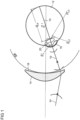
- Fig.1 shows a schematic representation of the physiological and physical model of a spectacle lens and an eye in a predetermined position of use together with an exemplary beam path, which forms the basis of an individual spectacle lens calculation or optimization according to a preferred embodiment of the invention.
- the main ray 10 which preferably runs through the eye rotation point Z'
- the derivatives of the wavefront's sagittal heights according to the transverse coordinates (perpendicular to the main ray) are taken into account. These derivatives are taken into account up to the desired order, with the second derivatives describing the local curvature properties of the wavefront and the higher derivatives being related to the imaging errors of higher orders.
- the local derivatives of the wave fronts are ultimately determined at a suitable position in the beam path in order to compare them there with a reference wave front which converges at a point on the retina of the eye 12.
- the two wave fronts i.e. the wave front coming from the lens and the reference wave front
- Porture does not simply mean a specific value of the z-coordinate (in the direction of light), but such a coordinate value in combination with the specification of all surfaces through which refraction took place before reaching the evaluation surface.
- refraction takes place through all refractive surfaces including the rear surface of the lens.
- the The reference wavefront is preferably a spherical wavefront whose center of curvature lies on the retina of the eye 12.
- the radius of curvature of this reference wave front corresponds exactly to the distance between the rear surface of the lens and the retina.
- the reference wavefront is spherical with the center of curvature on the retina, but has a radius of curvature 1/ d AR .
- a spherical wavefront w 0 emanates from the object point and propagates to the first lens surface 14. There it is refracted and then propagates to the second lens surface 16, where it is refracted again.
- the wavefront w g1 emerging from the lens then propagates along the main ray in the direction of the eye 12 (propagated wavefront w g2 ) until it hits the cornea 18, where it is again refracted (wavefront w c ).
- the wavefront is also refracted again by the eye lens 20, which creates the resulting wavefront w e , for example, on the back surface of the eye lens 20 or at the exit pupil of the eye.
- This is compared with the spherical reference wavefront w s and the deviations are evaluated for all viewing points in the target function (preferably with corresponding weightings for the individual viewing points).
- the refractive error is no longer described only by a thin sphero-cylindrical lens, as was the case in many conventional methods, but preferably the corneal topography, the eye lens, the distances in the eye and the deformation of the wavefront (including the low-order aberrations - i.e. sphere, cylinder and axis position - and preferably also including higher order aberrations) in the eye are taken into account directly.
- the vitreous body length d LR is calculated individually.
- an aberrometer measurement provides the individual wavefront deformations of the real ametropia eye for distance and near vision (deviations, not absolute refractive values) and the individual mesopic and photopic pupil diameters.
- an individual real corneal front surface is preferably obtained, which generally accounts for almost 75% of the eye's total refractive value.
- it is not necessary to measure the cornea's back surface. Due to the small difference in refractive index to the aqueous humor and the small corneal thickness, it is preferably described to a good approximation not by a separate refractive surface, but by an adjustment of the cornea's refractive index.
- bold lowercase letters denote vectors and bold uppercase letters denote matrices, such as the (2 x 2) vergence matrices or refractive power matrices
- S S x S xy S xy S yy
- C C x C xy C xy C yy
- L L x L xy L xy L yy
- 1 1 0 0 1 and italicized like d scalar quantities.
- S stands for the set of all parameters that are necessary to describe a wavefront (sufficiently precisely) in relation to a given coordinate system.
- S stands for a set of Zernike coefficients with a pupil radius or a set of coefficients of a Taylor series.
- S stands for the set of a Vergence matrix S to describe the wavefront properties of the second order and a set of Zernike coefficients (with a pupil radius) that serves to describe all remaining wavefront properties except the second order or a set of coefficients according to a Taylor decomposition.
- Analogous statements apply to surfaces instead of wavefronts.
- the division into steps 6a and 6b offers advantages, and preferably the Intermediate plane should be placed in the plane of the exit pupil AP, which is preferably located in front of the rear surface of the lens. In this case, ⁇ LR a ⁇ 0 and ⁇ LR b > 0 .
- the decisive factor for the choice of the evaluation surface of the wave front is not only the absolute position in relation to the z-coordinate (in the direction of the light), but also the number of surfaces through which the light has already refracted up to the evaluation surface. In this way, one and the same plane can be traversed several times.
- the plane of the AP (which normally lies between the front surface of the lens and the rear surface of the lens) is formally traversed by the light for the first time after an imaginary step 4a, in which the length of the front surface of the lens is reduced by ⁇ L a > 0
- steps 1 to 6 are referred to repeatedly in the further course of the description. They describe a preferred relationship between the vergence matrix S of a wave front S on the cornea and the vergence matrices of all resulting intermediate wave fronts on the refractive interfaces of the eye, in particular the vergence matrix S ' L 2 of a wave front S ' L 2 after the eye lens (or even a wave front S R on the retina). These relationships can be used both to calculate parameters that are not known a priori (e.g. d LR or L 1 ) and thus to assign values to the model either individually or generically, and to simulate the propagation of the wave front in the eye with the assigned models in order to optimize spectacle lenses.
- a priori e.g. d LR or L 1
- the surfaces and wavefronts are treated up to second order, for which a representation by vergence matrices is sufficient
- Another preferred embodiment described later also takes into account and uses higher orders of aberrations.
- the eye model in a preferred embodiment has twelve parameters as degrees of freedom of the model, which must be filled. These preferably include the three degrees of freedom of the surface refractive index matrix C of the cornea C , the three degrees of freedom of the surface refractive index matrices L 1 and L 2 for the front and back surfaces of the lens, respectively, as well as one each for the length parameters anterior chamber depth d CL , lens thickness d L and the vitreous body length d LR .
- a central aspect of the invention concerns the goal of not having to measure all parameters directly.
- at least one refraction i.e. measurement data on the wavefront S M of the eye up to the second order, is therefore available, which corresponds to the data in the vergence matrix S M.
- these values can be taken from aberrometric measurements or autorefractometric measurements, or can be documented according to (ii) data provided elsewhere.
- subjective methods i.e.
- the necessary data of the vergence matrix S M are available.
- the parameters ⁇ C , d CL , S M ⁇ are measured in particular.
- the two length parameters d L and d LR (or D LR ) are conventionally determined a priori (e.g. by literature values or estimation).
- the adaptation of L 1 to the measurements is done in particular by, on the one hand, calculating the measured vergence matrix S M using steps 1, 2 through the also measured matrix C and propagating it to the object-side side of the front surface of the lens.
- a spherical wave is calculated from an imaginary point-like light source on the retina using the backward steps 6, 5, 4 from back to front, by refracting this spherical wave at the previously determined surface refractive power matrix L 2 of the rear surface of the lens and propagating the resulting wave front from the rear surface of the lens to the image-side side of the front surface of the lens.
- the data of the vergence matrix S M and particularly preferably also the data on C are available from individual measurements.
- a spherical rear surface is assumed, ie a rear surface without astigmatic components.
- the anterior chamber depth d CL i.e. the distance between the cornea and the front surface of the lens
- the measured parameters therefore include ⁇ C , d CL , S M ⁇ .
- df 2 4 + 5 + 3 .
- the problem is therefore still mathematically underdetermined, so five parameters from ⁇ L 1 , L 2 , d L ⁇ must be determined a priori using assumptions or literature values. In a preferred embodiment, these are the parameters of the rear surface of the lens, the average curvature of the front surface of the lens and the lens thickness. The exact calculation method for this case is presented further below.
- these are the parameters of the rear surface of the lens and the lens thickness. The exact calculation is described further below.
- This embodiment is particularly advantageous when a pachymeter is used whose measurement depth allows the detection of the rear surface of the lens, but not a sufficiently reliable determination of the lens curvature.
- the anterior chamber depth, two or three parameters of the anterior lens surface and the lens thickness are measured individually.
- the calculation of the remaining variables is carried out analogously, whereby the a priori assumption of the lens thickness can be replaced by the corresponding measurement.
- individual measurements of the anterior chamber depth, at least one parameter of the front surface of the lens, the lens thickness and at least one parameter of the back surface of the lens are provided.
- the respective additionally measured parameters can be carried out analogously to the step-by-step extensions of the above sections.
- a measurement of the curvature of a lens surface in a normal section is available. Since in practice the back surface cannot be measured without also measuring the front surface, and the measurement of the front surface is preferred, the equations for cases where the curvature of the front surface of the lens is known in a normal section are given below. If a normal section of the back surface of the lens is given instead of a normal section of the front surface of the lens (e.g. corresponding measurements, model assumptions), an analogous procedure must be followed with equation (1b). Without loss of generality, the coordinate system is laid out so that the normal section runs in the x direction. In a next step, the matrix equation (1a) is evaluated in the given normal section and solved for D LR , and this solution is then inserted back into equation (1a) to fully specify L 1 .
- an individual measurement or a specification of a mean curvature of a lens surface is available. This situation arises, for example, when the mean curvature of the front surface of the lens can be measured or no measurements can be carried out on the lens surfaces and the mean curvature of a lens surface is assumed (e.g. taken from the literature). As just now, the method is also described here for the front surface of the lens and can be transferred analogously to the rear surface of the lens.
- the free parameters are the cylinder L 1, cyl and the axis position ⁇ L 1 .
- L 1, diff L 1, cyl / 2
- L 1 L 1 , ms ⁇ L 1 , diff ⁇ cos 2 ⁇ L 1 ⁇ L 1 , diff ⁇ sin 2 ⁇ L 1 ⁇ L 1 , diff ⁇ sin 2 ⁇ L 1 L 1 , ms + L 1 , diff ⁇ cos 2 ⁇ L 1
- the given (i.e. measured or assumed) sizes can be a main section with a given angular position or the mean curvature, as well as other parameters such as the strongest main section, the weakest main section, the cylinder and the axis position.
- the procedure in these cases is analogous to the cases described.
- HOA the HOA of the eye is now also taken into account when optimizing spectacle lenses, it is advantageous to also consider the HOA of the cornea or lens when assigning the eye model.
- HOA the general rule is that HOA can be assigned to the front or back surface of the lens, which can also depict the refractive index curve within the lens.
- the formalism presented so far is extended to the treatment of the HOA, in particular with regard to the steps 1 to 6 mentioned above, by using, in addition to the formulas for the vergence matrices explicitly given in steps 1 to 6, the calculation methods from the publications of G. Esser et al.: “Derivation of the refraction equations for higher order aberrations of local wavefronts at oblique incidence", JOSA A, Vol. 27, No. 2 (2010 ) and by G. Esser et al.: “Derivation of the propagation equations for higher order aberrations of local wavefronts, JOSA A, Vol. 28, No. 11 (2011 )” may be applied.
- the procedure for counting degrees of freedom is very similar to that described above. If, in addition to data on second order errors, data on the HOA of the refractive surface C of the cornea and the emerging wavefront S M are available (either from measurements or from reasonable assumptions), then the wave front S L 1 can also be determined mathematically with a corresponding number of HOAs. This applies regardless of the form of representation of the HOA. However, the Taylor series is particularly preferred because in this form the following statement applies exactly: If HOA coefficients up to order n are given for both surfaces C and S M , then the corresponding HOA coefficients for S L 1 up to order n can also be determined mathematically from them. The Zernike basis is also preferred because a similar statement applies here too. However, this is only exact if all Zernike coefficients with an order > n disappear.
- an order n is defined (in advance) up to which all surfaces and wave fronts involved are to be treated.
- the adaptation condition based on a measured wavefront e.g. S M,L 1
- N + 3 3N + 12 parameters (namely the three length parameters d CL , d L and d LR (or D LR ) as well as N + 3 components each from the cornea C and the lens surfaces L 1 and L 2 ).
- the measuring device on which the procedure described here is based can be used with the aberrometry unit to measure the HOA of the image of the eye on the retina in transmission. Furthermore, the HOA of the corneal surface can be measured in reflection using the same device through the topography unit. This means that both the emerging wavefront S M and the refractive surface C of the cornea, including the HOA up to a certain order n, are available.
- the HOA of the lens when the model is loaded, can be selected such that the measured wavefront is created when a wavefront emanating from a point on the retina is propagated in accordance with steps 1 to 6 in reverse order.
- At least the length parameter d LR is neither specified a priori nor individually measured, but is calculated based on the individual refraction data and the other (pre-)defined data.
- at least one measured value or assumption is provided, in particular for one of the degrees of freedom of lens surfaces L 1 or L 2. If this is, for example, a measured value for the curvature of L 1 in a normal section, then d LR (or D LR ) can be determined from this by calculation.
- the information in the vergence matrices refers to the local curvature (this corresponds to the information of the HOA as coefficients of a Taylor decomposition)
- first D LR and the missing parameters of the lens are determined as described above. Then, using the formalism from G. Esser et al.: “Derivation of the refraction equations for higher order aberrations of local wavefronts at oblique incidence", JOSA A, Vol. 27, No. 2 (2010 ) and from G. Esser et al.: “Derivation of the propagation equations for higher order aberrations of local wavefronts, JOSA A, Vol. 28, No. 11 (2011 )" the HOA of the lens is gradually built up starting from the second to the n-th order.
- model-based assumptions about the HOA of the cornea, the lens or the eye can still be made and used when populating the eye model.
- the assumed values can also be selected using appropriate models depending on measured data (e.g. refraction values, results of topometry or autorefractometer measurements). Examples of the exact calculation have already been described above, with the corresponding assumptions taking the place of the measured values for the HOAs. This is again particularly true for spherical aberrations, since these are significantly different from zero on average across the population. These can be selected independently of the measured data or depending on measured data (e.g. refraction values, results of topometry or autorefractometer measurements) and assigned to the cornea, one of the two lens surfaces or combinations.
- Subjective refraction data are preferably provided in the form of sphere, cylinder and axial position.
- Subjective refraction data are preferably provided in the form of sphere, cylinder and axial position.
- the description of the procedure is based on this notation with sph, cyl and a for the values of sphere, cylinder and axial position.
- the results of the subjective refraction are combined with those of the aberrometric or autorefractometric measurement.
- an optimized refraction is calculated on the basis of both data sets, for example according to a EN 10 2007 032 564 A1 This is described by the values sph opt , cyl opt and a opt .
- the HOA can also be taken into account when filling the model.
- the subjective refraction values it is necessary to incorporate them into the data set in a consistent manner.
- a formalism based on Zernike coefficients is chosen below, although in principle another basis can also be used.
- the relationship between a set of Zernike coefficients for representing wavefronts ( c nm ) with r 0 as the radius of the wavefront and refraction values ( sph, cyl, a ) is considered.
- the radius r 0 is preferably either measured or determined on the basis of model assumptions.
- autorefractometric measurements with data on HOA are available, these data or parts of these data can be used together with the subjective refraction values, for example according to EN 10 2007 032 564 A1 to determine a set of optimized refraction data.
- the simultaneous use of both subjective refraction data and the measurement data is not necessary.
- the values referred to in this section as optimized refraction values ( sph opt , cyl opt and a opt ) can therefore also be taken directly from the subjective refraction determination without using objective measurement values.
- not all values of the subjective refraction or objective measurement have to be included in the optimized refraction values.
- the use of the objectively measured sphere or the objectively measured defocus term can be dispensed with.
- a wavefront (preferably represented by the Zernike coefficients o i,j ) is then determined that corresponds to these optimized values. This wavefront is then used instead of the measured outgoing wavefront described above.
- the evaluation of the aberrations during the calculation or optimization process can be carried out at different points in the beam path, i.e. the evaluation surface can be provided at different positions.
- the imaging wavefront can also be evaluated at an area further forward in the model eye.
- a reference wavefront R is defined within the model eye, which is then used, for example, in lens optimization.
- This reference wavefront has the property that it leads to a point-like image when propagated further through the eye to the retina.
- the reference wavefront can be determined by backpropagating a wavefront that converges to a point on the retina, from the retina to the position of the reference wavefront. Since the measured wavefront S M is exactly the wavefront that arises from a point-like light source on the retina, this can also be propagated into the interior of the eye to the position of the reference wavefront instead.
- lens optimization that evaluates an imaging wavefront by comparing it with a reference wavefront generally leads to different results depending on the area within the eye where this comparison takes place.
- step 6b only the very last step (in particular step 6b), i.e. the propagation from the AP to the retina, is omitted.
- the incident wave front is thus only simulated up to the AP after refraction at the rear surface of the lens (i.e. calculation of S AP according to step 6a mentioned above) and compared there with a reference wave front R AP .
- This is characterized by the fact that it produces a point-like image when propagated to the retina.
- the penultimate Step i.e. the propagation from the rear surface of the lens to the retina is omitted.
- the incident wave front is therefore only simulated up to the point of refraction at the rear surface of the lens (i.e. calculation of S ' L2 according to step 5 mentioned above) and compared there with a reference wave front R ' L2 .
- This is characterized by the fact that it produces a point-like image when propagated to the retina.
- a further simplification is achieved if the comparison is made before the refraction through the rear surface of the lens.
- the incident wave front only has to be simulated, i.e. calculated, up to S L2 according to step 4 above.
- Another very efficient option is to position the evaluation surface at the exit pupil of the model eye. This is preferably located in front of the back surface of the lens.
- the eye model and its occupancy can be extended as follows: Basically, the eye model can distinguish between the cornea and the anterior chamber.
- a corneal posterior surface C 2 is introduced behind the corneal anterior surface C 1 (formerly C ) at a distance d C and two different refractive indices n C and n CL are specified for the cornea and the anterior chamber.
- the values for d C and C 2 can be measured, taken from the literature or derived. Some possibilities for C 2 are described here as examples: If no measurement is available on the back surface of the cornea, the shape of the back surface of the cornea can be taken from known eye models. Alternatively, in this case, the back surface of the cornea can also be derived from the measured shape of the front surface of the cornea. To do this, it is advisable to assume either a uniform corneal thickness (defined, for example, as “in the direction of the arrow height" or "in the radial direction starting from a "corneal curvature center”). The thickness can either be taken from a measurement, derived from this, or taken from the literature. Furthermore, local properties can also be only partially transferred to the back surface.
- this information can be used to reconstruct the complete posterior surface. This can be done, for example, by setting up a function of the thickness or sagittal height of the posterior surface of the cornea from the radius or the thickness of the sagittal height of the anterior surface.
- the front and back surfaces of the cornea will be known in the same normal section (i.e. here in the x-direction).
- the fact that the human eye is a non-centered optical system can be taken into account by arranging the optical elements offset and/or tilted against a central axis.
- the corresponding parameters are, for example, two lateral coordinates of the displacement of the center of the element or surface from the central axis and two tilt angles.
- first-order Zernike coefficients tip/tilt can also be used.
- the main beam which is the basis of the invention for all calculations and corresponds to the centered systems of the optical axis discussed so far.
- the main ray is the ray that emanates from the retina as the center of the measurement wavefront (preferably the location of the fovea) and hits the center of the entrance pupil.
- this ray coincides with the global z-axis of the eye model in suitable coordinates, the ray is now only straight in sections from interface to interface and also hits each interface decentered and at certain angles of incidence.
- the positions of the intersection points and the respective angles of incidence must be determined.
- ⁇ is the curvature of the refracting surface and n, n' are the refractive indices before and after refraction.
- ⁇ r and ⁇ ⁇ are correction components of the beam parameters, which are caused by the lateral displacement and the tilting of the refracting interface, and are determined from the tilting and displacement parameters of the surface using Prentice's rule.
- the 4x4 transfer matrix equations must be used accordingly.
- the main ray i.e. all intersection points through the surfaces
- the determination of the main ray results in all propagation distances, the coordinates of the intersection points and the angles of incidence and reflection ⁇ , ⁇ ' being determined at each interface.
- ⁇ , ⁇ ' result from ⁇ , ⁇ ', and the surface normals, which can be determined from r , the decentration and the dioptric power according to Prentice's rule at the intersection point.
- ⁇ , ⁇ ' result from the numerical calculation of the main ray and the surface normals at the intersection point r .
- the surface refractive power matrix C is constant and given by the respective refractive element.
- C is obtained at the intersection point by the local second derivatives with respect to a local coordinate system.
- the calculation methods of the invention can also be applied to decentered systems as described below:
- d ⁇ ,r denotes the actual spatial distance between the intersection points of the consecutive surfaces.
- an aperture - also shifted or tilted - can be introduced to take into account the vignetting caused by the iris
- Fig.1 shows a schematic representation of the physiological and physical model of a spectacle lens and an eye in a given position of use together with an exemplary beam path which forms the basis of an individual spectacle lens calculation or optimization according to a preferred embodiment of the invention.
- the main ray 10 which preferably runs through the eye rotation point Z'
- the derivatives of the wavefront's sagittal heights according to the transverse coordinates (perpendicular to the main ray) are taken into account. These derivatives are taken into account up to the desired order, with the second derivatives describing the local curvature properties of the wavefront and the higher derivatives being related to the imaging errors of higher orders.
- the local derivatives of the wave fronts are ultimately determined at a suitable position in the beam path in order to compare them there with a reference wave front which converges at a point on the retina of the eye 12.
- the two wave fronts i.e. the wave front coming from the lens and the reference wave front
- “Position” does not simply mean a specific value of the z-coordinate (in the direction of light), but rather such a coordinate value in combination with the specification of all surfaces through which refraction occurred before reaching the evaluation surface.
- refraction occurs through all refractive surfaces including the rear surface of the lens.
- the reference wavefront is preferably a spherical wavefront whose center of curvature lies on the retina of the eye 12.
- the radius of curvature of this reference wave front corresponds exactly to the distance between the rear surface of the lens and the retina.
- the reference wavefront is spherical with the center of curvature on the retina, but has a radius of curvature 1/ d AR .
- a spherical wavefront w 0 emanates from the object point and propagates to the first lens surface 14. There it is refracted and then propagates to the second lens surface 16, where it is refracted again.
- the wavefront w g1 emerging from the lens then propagates along the main ray in the direction of the eye 12 (propagated wavefront w g2 ) until it hits the cornea 18, where it is again refracted (wavefront w c ).
- the wavefront is also refracted again by the eye lens 20, which creates the resulting wavefront w e , for example, on the back surface of the eye lens 20 or at the exit pupil of the eye.
- This is compared with the spherical reference wavefront w s and the deviations are evaluated for all viewing points in the target function (preferably with corresponding weightings for the individual viewing points).
- the refractive error is no longer only described by a thin sphero-cylindrical lens, as was common in many conventional methods, but preferably the corneal topography, the eye lens, the distances in the eye and the deformation of the wavefront (including the low-order aberrations - i.e. sphere, cylinder and axis position - and preferably also including the higher-order aberrations) in the eye are directly taken into account.
- an aberrometer measurement provides the individual wavefront deformations of the real ametropia eye for distance and near (deviations, not absolute refractive values) and the individual mesopic and photopic pupil diameters.
- a measurement of the corneal topography areal measurement of the cornea's front surface
- bold lowercase letters denote vectors and bold uppercase letters denote matrices, such as the (2 x 2) vergence matrices or refractive power matrices
- S S x S xy S xy S yy
- C C x C xy C xy C yy
- L L x L xy L xy L yy
- 1 1 0 0 1 and italicized like d scalar quantities.
- HOA totality of all higher order aberrations
- S stands for the set of all parameters that are necessary to describe a wavefront (sufficiently accurately) in relation to a given coordinate system.
- S stands for a set of Zernike coefficients with a pupil radius or a set of coefficients from a Taylor series.
- S stands for the set of a vergence matrix S to describe the 2nd order wavefront properties and a set of Zernike coefficients (with a pupil radius), which serves to describe all remaining wavefront properties except for the 2nd order, or a set of coefficients according to a Taylor decomposition.
- Analogous statements apply to surfaces instead of wave fronts.
- the division into steps 6a and 6b offers advantages, and preferably the intermediate plane can be placed in the plane of the exit pupil AP, which is preferably located in front of the rear surface of the lens. In this case, ⁇ LR a ⁇ 0 and ⁇ LR b > 0 .
- the decisive factor for the choice of the evaluation surface of the wave front is not only the absolute position in relation to the z-coordinate (in the direction of the light), but also the number of surfaces through which the light has already refracted up to the evaluation surface. In this way, one and the same plane can be traversed several times.
- the plane of the AP which normally lies between the front surface of the lens and the rear surface of the lens
- the plane of the AP is formally traversed by the light for the first time after an imaginary step 4a, in which the length of the front surface of the lens is reduced by ⁇ L a > 0 is being propagated.
- steps 1 to 6 are referred to repeatedly in the further course of the description. They describe a preferred relationship between the vergence matrix S of a wave front S on the cornea and the vergence matrices of all resulting intermediate wave fronts on the refractive interfaces of the eye, in particular the vergence matrix S' L 2 of a wave front S ' L 2 after the eye lens (or even a wave front S R on the retina). These relationships can be used both to calculate parameters that are not known a priori (e.g. d LR or L 1 ) and thus to assign values to the model either individually or generically, and to simulate the propagation of the wave front in the eye with the assigned models in order to optimize spectacle lenses.
- a priori e.g. d LR or L 1
- the eye model in a preferred embodiment has twelve parameters as degrees of freedom of the model, which must be filled. These preferably include the three degrees of freedom of the surface refractive index matrix C of the cornea C , the three degrees of freedom of the surface refractive index matrices L 1 and L 2 for the front and back surfaces of the lens, respectively, as well as one each for the length parameters anterior chamber depth d CL , lens thickness d L and vitreous length d LR .
- At least one refraction i.e. measurement data on the wavefront S M of the eye up to the second order, is available, which corresponds to the data of the vergence matrix S M.
- these values can be taken from autorefractometric measurements, for example, or can be documented according to (ii) other data provided.
- the necessary data of the vergence matrix S M are available.
- the parameters ⁇ C , d CL , S M ⁇ are measured in particular.
- the two length parameters d L and d LR (or D LR ) are preferably determined a priori (e.g. by literature values or estimation).
- the adaptation of L 1 to the measurements is done in particular by, on the one hand, calculating the measured vergence matrix S M through the also measured matrix C using steps 1, 2 and propagating it to the object-side side of the front surface of the lens.
- a spherical wave is calculated from an imaginary point-like light source on the retina using the backward steps 6, 5, 4 from back to front, by refracting this spherical wave at the previously determined surface refractive power matrix L 2 of the rear surface of the lens and propagating the wave front thus obtained from the rear surface of the lens to the image-side side of the front surface of the lens.
- At least one of the length parameters d L and d LR is calculated from other measured data and a priori assumptions about other degrees of freedom and in particular is not itself assumed a priori.
- the data of the vergence matrix S M and particularly preferably also the data on C are available from individual measurements.
- a spherical rear surface is assumed, ie a rear surface without astigmatic components.
- the anterior chamber depth d CL i.e. the distance between the cornea and the front surface of the lens
- the measured parameters therefore include ⁇ C , d CL , S M ⁇ .
- df 2 4 + 5 + 3.
- the problem is therefore still mathematically underdetermined, so five parameters from ⁇ L 1 , L 2 , d L ⁇ must be determined a priori by assumptions or literature values.
- these are the parameters of the rear surface of the lens, the average curvature of the front surface of the lens and the lens thickness. The exact calculation method for this case is presented further below.
- these are the parameters of the rear surface of the lens and the lens thickness. The exact calculation is described further below.
- This embodiment is particularly advantageous when a pachymeter is used whose measurement depth allows the detection of the rear surface of the lens, but not a sufficiently reliable determination of the lens curvature.
- the anterior chamber depth, two or three parameters of the anterior lens surface and the lens thickness are measured individually.
- the calculation of the remaining variables is carried out analogously, whereby the a priori assumption of the lens thickness can be replaced by the corresponding measurement.
- individual measurements of the anterior chamber depth, at least one parameter of the front surface of the lens, the lens thickness and at least one parameter of the back surface of the lens are provided.
- the respective additionally measured parameters can be carried out analogously to the step-by-step extensions of the above sections.
- a measurement of the curvature of a lens surface in a normal section For example, in preferred embodiments, a measurement of the curvature of a lens surface in a normal section. Since in practice the back surface cannot be measured without also measuring the front surface, and the measurement of the front surface is preferred, the equations for cases where the curvature of the front surface of the lens is known in a normal section are given below. If a normal section of the back surface of the lens is given instead of a normal section of the front surface of the lens (e.g. corresponding measurements, model assumptions), an analogous procedure must be followed using Eq.(1b). Without loss of generality, the coordinate system is laid out so that the normal section runs in the x direction. In the next step, the matrix equation (1a) is evaluated in the given normal section and solved for D LR , and this solution is then inserted back into Eq.(1a) to fully specify L 1 .
- an individual measurement or a specification of a mean curvature of a lens surface is available. This situation occurs, for example, when the mean curvature of the front surface of the lens can be measured or no measurements can be carried out on the lens surfaces and the mean curvature of a lens surface is assumed (e.g. taken from the literature). As just now, the method is also described here for the front surface of the lens and can be transferred analogously to the rear surface of the lens. In this case, given a mean sphere L 1, ms of the front surface of the lens, the free parameters are the cylinder L 1, cyl and the axis position ⁇ L 1 .
- L 1 L 1 , ms ⁇ L 1 , diff ⁇ cos 2 ⁇ L 1 ⁇ L 1 , diff ⁇ sin 2 ⁇ L 1 ⁇ L 1 , diff ⁇ sin 2 ⁇ L 1 L 1 , ms + L 1 , diff ⁇ cos 2 ⁇ L 1
- the given (i.e. measured or assumed) sizes can be a main section with a given angular position or the mean curvature, as well as other parameters such as the strongest main section, the weakest main section, the cylinder and the axis position.
- the procedure in these cases is analogous to the cases described.
- HOA of the eye Since the HOA of the eye is now also taken into account when optimizing spectacle lenses, it is advantageous to also consider the HOA of the cornea or lens when assigning the eye model.
- HOAs can be assigned to the front and back surfaces of the lens, which can also depict the refractive index profile within the lens.
- the formalism presented so far is extended to the treatment of the HOA, in particular with regard to the steps 1 to 6 mentioned above, by using, in addition to the formulas for the vergence matrices explicitly given in steps 1 to 6, the calculation methods from the publications of G. Esser et al.: “Derivation of the refraction equations for higher order aberrations of local wavefronts at oblique incidence", JOSA A, Vol. 27, No. 2 (2010 ) and from G. Esser et al.: “Derivation of the propagation equations for higher order aberrations of local wavefronts, JOSA A, Vol. 28, No. 11 (2011 )” may be applied.
- the procedure for counting degrees of freedom is very similar to that described above. If, in addition to data on 2nd order errors, data on the HOA of the refracting surface C of the cornea and the emerging wavefront S M are also available (either from measurements or from reasonable assumptions), then the wavefront S L 1 can also be calculated using a corresponding number of HOAs. This applies regardless of the form of representation of the HOA.
- the Taylor series is particularly preferred, however, because in this form the following statement applies exactly: If HOA coefficients up to order n are given for both surfaces C and S M , then the corresponding HOA coefficients for S L 1 up to order n can also be calculated from them.
- the Zernike basis is also preferred, because a similar statement applies here too. However, this is only exact if all Zernike coefficients with an order > n vanish.
- an order n is defined (in advance) up to which all surfaces and wave fronts involved are to be treated.
- the adaptation condition based on a measured wavefront e.g. S M,L 1
- N + 3 3N + 12 parameters (namely the three length parameters d CL , d L and d LR (or D LR ) as well as N + 3 components each from the cornea C and the lens surfaces L 1 and L 2 ).
- the HOA of the image of the eye on the retina can be recorded in transmission using suitable measuring devices with an aberrometry unit.
- the HOA of the corneal surface can be measured in reflection using a topography unit. This then provides data on the emerging wavefront S M as well as a description of the refractive surface C of the cornea, including the HOA up to a certain order n.
- the HOA of the lens can be selected such that the measured wavefront is created when a wavefront emanating from a point on the retina is propagated according to steps 1 to 6 in reverse order.
- the propagation of this wavefront emanating from a point on the retina to the evaluation surface can lead to the reference wavefront, which is then used for comparison with the wavefront emanating from an object.
- a spherical wave is calculated from an imaginary point-like light source on the retina by means of the backward steps 6, 5, 4 from back to front, by refracting this spherical wave at the previously determined lens rear surface L 2 and propagating the wave front obtained from the lens rear surface to the image side of the lens front surface L 1 .
- the two wave fronts S L 1 and S' L1 determined in this way which lie on the object side and the image side of the lens front surface respectively, generally have both low-order aberrations and HOA, the values of which, however, differ between the two wave fronts. Since the two wave fronts occur in one and the same measuring beam path and therefore have to be connected via the still missing step 3, this difference can be used to unambiguously deduce the refracting lens front surface L 1 up to order n , for example by the G. Esser et al.: “Derivation of the refraction equations for higher order aberrations of local wavefronts at oblique incidence", JOSA A, Vol. 27, No. 2 (2010 ) and from G. Esser et al.: “Derivation of the propagation equations for higher order aberrations of local wavefronts, JOSA A, Vol. 28, No. 11 (2011 )” calculation methods.
- G. Esser et al. “Derivation of the refraction equations for higher order aberrations of local wavefronts at oblique incidence", JOSA A, Vol. 27, No. 2 (2010 ) and in G. Esser et al.: “Derivation of the propagation equations for higher order aberrations of local wavefronts, JOSA A, Vol. 28, No. 11 (2011 )” for the refraction and propagation steps.
- any surface or wave front that is not in this form is preferably first brought into this form. This can be done, for example, by transforming a Zernike representation to the representation by local derivatives, or by a previous fit of a sag representation.
- a suitable technical form of representation of surfaces by Taylor coefficients is, for example, in WO 2013/104548 A1 described.
- the deviations can also be distributed over the front and rear surfaces of the lens.
- At least one of the Length parameters d L and d LR are neither specified a priori nor individually measured, but are calculated based on the individual refraction data and the other (pre-)determined data.
- at least one measured value or assumption is provided for one of the degrees of freedom of the lens surfaces L 1 or L 2. If this is, for example, a measured value for the curvature of L 1 in a normal section, then d LR (or D LR ) in particular can be determined from this by calculation.
- the information in the vergence matrices refers to the local curvature (this corresponds to the information of the HOA as coefficients of a Taylor decomposition)
- first D LR and the missing parameters of the lens are determined as described above. Then, using the formalism from G. Esser et al.: “Derivation of the refraction equations for higher order aberrations of local wavefronts at oblique incidence", JOSA A, Vol. 27, No. 2 (2010 ) and from G. Esser et al.: “Derivation of the propagation equations for higher order aberrations of local wavefronts, JOSA A, Vol. 28, No. 11 (2011 )" the HOA of the lens is gradually built up starting from the second to the n-th order.
- the HOA of the image of the eye on the retina can be recorded in transmission using suitable measuring devices with an aberrometry unit.
- aberrometry units for recording HOA are quite complex and are not available to every optician.
- this does not provide data on the emerging wave front S M, it does at least provide a description of the refractive surface C of the cornea, including the HOA up to a certain order n.
- the invention offers the possibility of using the individual eye model, even if individual measurements of the HOA of the cornea but no individual measurements of the HOA of the eye are available.
- an autorefractometer i.e. no measurement of the HOA
- an aberrometer also in combination with a subjective refraction
- the vergence matrix S M of the LOA is known, but beyond that there is no individual information about the HOA of the (measurement beam path) wavefront S M of the entire eye.
- this case can be treated in the same way as described above when measured HOA of the eye is present, if assumptions are made about the HOA of the eye.
- An example of this are values determined using a group of test subjects or model-based values.
- a remaining spherical aberration is preferably assumed, since TO Salmon and C. van de Pol: Normal-eye Zernike coefficients and root-mean-square wavefront errors, J Cataract Refract Surg, Vol. 32, pages 2064-2074 (2006 ) and from J. Porter et al.: Monochromatic aberrations of the human eye in a large population, JOSA A, Vol. 18, No. 8 (2001 ) it is known that this is significantly different from zero on average across the population.
- the calculation of the HOA of the lens is then carried out in a similar way to the procedure described above, with the only difference being that the HOA values for S M are not taken from an individual measurement, but are based on the assumptions mentioned above.
- the HOA of both lens surfaces L 1 and L 2 are determined a priori, for example, using the algorithms from G. Esser et al.: “Derivation of the refraction equations for higher order aberrations of local wavefronts at oblique incidence", JOSA A, Vol. 27, No. 2 (2010 ) and from G. Esser et al.: “Derivation of the propagation equations for higher order aberrations of local wavefronts, JOSA A, Vol. 28, No. 11 (2011 )"
- the HOA of the wavefront S M can be calculated up to order n by going through steps 6,5,4,3,2,1 backwards from the retina to the cornea.
- the a priori determined d L and d LR are also included in the calculation of S M.
- HOA of the lens surfaces in the basis used is set equal to zero. This assumption is particularly preferred in relation to the Taylor basis. This assumption is also preferred in relation to the Zernike basis.
- HOA of S M is not a direct image of the HOA of C in any basis, because the propagations involved always introduce HOA, the advantage of vanishing HOA of the lens surfaces is the reduction in the computational effort due to many vanishing terms.
- model-based values for the HOA of the lens surfaces can be selected. This is especially true for spherical aberrations, since TO Salmon and C. van de Pol: Normal-eye Zernike coefficients and root-mean-square wavefront errors, J Cataract Refract Surg, Vol. 32, pages 2064-2074 (2006 ) and from J. Porter et al.: Monochromatic aberrations of the human eye in a large population, JOSA A, Vol. 18, No. 8 (2001 ) it is known that the spherical aberration of the lens is significantly different from zero on average over the population. These can be selected independently of the measured data or depending on measured data (eg refraction values, spherical aberration of the cornea).
- the present invention offers the possibility of inferring S M by measurements of or assumptions about L 1 and L 2 . Meaningful values for the HOA of S M are thus obtained without aberrometric measurements. This does not require precise knowledge of the length parameters d L and d LR (or D LR ), so that the formalism can also be used without the calculation of d LR described in section 3. In contrast to the second-order errors of the wavefront S M, the HOA of S M depend only so weakly on the length parameters d L and d LR (or D LR ) that the choice of the a priori values for d L and d LR - within the physiologically reasonable range - has only little influence on the adjustment of the HOA of S M and consequently standard parameters can also be used.
- lens optimizations can be carried out taking into account the HOA of the eye, such as the DNEye optimization, even without individual aberrometric measurements (e.g. based on topography measurements).
- the evaluation of aberrations during the calculation or optimization process can be carried out at different points in the beam path carried out, i.e. the evaluation area can be provided at different positions.
- the imaging wavefront can also be evaluated at an area further forward in the model eye.
- a reference wavefront R is defined within the model eye, which is then used, for example, in lens optimization.
- This reference wavefront has the property that it leads to a point-shaped image when propagated further through the eye to the retina.
- the reference wavefront can be determined by backpropagation of a wavefront that converges to a point on the retina, from the retina to the position of the reference wavefront. Since, for example, the measured wavefront S M is exactly the wavefront that emanates from a point-shaped light source on the retina, this can also be propagated into the interior of the eye to the position of the reference wavefront instead.
- lens optimization that evaluates an imaging wavefront by comparing it with a reference wavefront generally leads to different results depending on the area within the eye where this comparison takes place.
- step 6b only the very last step (in particular step 6b), i.e. the propagation from the AP to the retina, is omitted.
- the incident wave front is thus only simulated up to the AP after refraction at the rear surface of the lens (i.e. calculation of S AP according to step 6a mentioned above) and compared there with a reference wave front R AP .
- This is characterized by the fact that it produces a point-like image when propagated to the retina.
- the penultimate step i.e. the propagation from the rear surface of the lens to the retina
- the incident wave front is therefore only simulated up to the point after refraction at the rear surface of the lens (i.e. calculation of S ' L 2 according to step 5 mentioned above) and compared there with a reference wave front R' L 2.
- R' L 2 the vergence matrix of this wave front
- a further simplification is achieved if the comparison is made before the refraction through the rear surface of the lens.
- the incident wave front only has to be simulated, i.e. calculated, up to S L 2 according to step 4 above.
- Another very efficient option is to position the evaluation surface at the exit pupil of the model eye. This is preferably located in front of the back surface of the lens.
Landscapes
- Health & Medical Sciences (AREA)
- Life Sciences & Earth Sciences (AREA)
- Physics & Mathematics (AREA)
- Ophthalmology & Optometry (AREA)
- General Health & Medical Sciences (AREA)
- Engineering & Computer Science (AREA)
- Medical Informatics (AREA)
- Public Health (AREA)
- Biomedical Technology (AREA)
- Surgery (AREA)
- Heart & Thoracic Surgery (AREA)
- Veterinary Medicine (AREA)
- Animal Behavior & Ethology (AREA)
- Molecular Biology (AREA)
- Biophysics (AREA)
- General Physics & Mathematics (AREA)
- Optics & Photonics (AREA)
- Primary Health Care (AREA)
- Epidemiology (AREA)
- Databases & Information Systems (AREA)
- Mathematical Physics (AREA)
- Data Mining & Analysis (AREA)
- Pathology (AREA)
- Signal Processing (AREA)
- Urology & Nephrology (AREA)
- Nuclear Medicine, Radiotherapy & Molecular Imaging (AREA)
- Eyeglasses (AREA)
- Eye Examination Apparatus (AREA)
Applications Claiming Priority (5)
| Application Number | Priority Date | Filing Date | Title |
|---|---|---|---|
| DE102017000772 | 2017-01-27 | ||
| DE102017007990.0A DE102017007990B4 (de) | 2017-01-27 | 2017-08-23 | Computerimplementierte Verfahren und Vorrichtungen zum Ermitteln individueller Aberrationsdaten oder zum Berechnen oder Optimieren eines Brillenglases für zumindest ein Auge eines Brillenträgers, Computerimplementiertes Verfahren zum Ermitteln optimierter sphärozylindrischer Werte für zumindest ein Auge eines Brillenträgers, Verfahren und Vorrichtung zum Herstellen eines Brillenglases, Brillengläser und Computerprogrammerzeugnis |
| DE102017007975.7A DE102017007975B4 (de) | 2017-01-27 | 2017-08-23 | Computerimplementiertes Verfahren, Vorrichtung und Computerprogrammerzeugnis für die Belegung eines Augenmodells zur Optimierung von Brillengläsern mit Messdaten |
| EP18706394.6A EP3574367B1 (fr) | 2017-01-27 | 2018-01-24 | Application de données de mesure à un modèle oculaire pour optimiser des lunettes |
| PCT/EP2018/051715 WO2018138140A2 (fr) | 2017-01-27 | 2018-01-24 | Application de données de mesure à un modèle oculaire pour optimiser des lunettes |
Related Parent Applications (1)
| Application Number | Title | Priority Date | Filing Date |
|---|---|---|---|
| EP18706394.6A Division EP3574367B1 (fr) | 2017-01-27 | 2018-01-24 | Application de données de mesure à un modèle oculaire pour optimiser des lunettes |
Publications (2)
| Publication Number | Publication Date |
|---|---|
| EP4435497A2 true EP4435497A2 (fr) | 2024-09-25 |
| EP4435497A3 EP4435497A3 (fr) | 2024-11-27 |
Family
ID=62842898
Family Applications (2)
| Application Number | Title | Priority Date | Filing Date |
|---|---|---|---|
| EP24186008.9A Pending EP4435497A3 (fr) | 2017-01-27 | 2018-01-24 | Occupation d'un modèle oculaire pour optimiser des verres de lunettes avec des données de mesure |
| EP18706394.6A Active EP3574367B1 (fr) | 2017-01-27 | 2018-01-24 | Application de données de mesure à un modèle oculaire pour optimiser des lunettes |
Family Applications After (1)
| Application Number | Title | Priority Date | Filing Date |
|---|---|---|---|
| EP18706394.6A Active EP3574367B1 (fr) | 2017-01-27 | 2018-01-24 | Application de données de mesure à un modèle oculaire pour optimiser des lunettes |
Country Status (8)
| Country | Link |
|---|---|
| US (2) | US11561413B2 (fr) |
| EP (2) | EP4435497A3 (fr) |
| JP (1) | JP7395351B2 (fr) |
| BR (1) | BR112019014840B1 (fr) |
| DE (3) | DE102017007974A1 (fr) |
| ES (1) | ES2988483T3 (fr) |
| IL (2) | IL301879B2 (fr) |
| WO (1) | WO2018138140A2 (fr) |
Families Citing this family (13)
| Publication number | Priority date | Publication date | Assignee | Title |
|---|---|---|---|---|
| CN114173635B (zh) * | 2019-07-02 | 2025-10-17 | 罗登斯托克有限责任公司 | 优化眼镜镜片、特别是用于植入式人工晶状体的佩戴者的眼镜镜片的方法和设备 |
| JP7356940B2 (ja) * | 2020-03-23 | 2023-10-05 | ホヤ レンズ タイランド リミテッド | レンズ評価方法、レンズ設計方法、眼鏡レンズの製造方法およびレンズ評価プログラム |
| DE102020128951B4 (de) * | 2020-11-03 | 2022-07-28 | Rodenstock Gmbh | Verfahren zum Herstellen eines Brillenglases, Computerprogrammprodukt und Vorrichtung zum Bestimmen zumindest eines individuellen biometrischen Parameters |
| DE102020128958B4 (de) * | 2020-11-03 | 2022-07-28 | Rodenstock Gmbh | Verfahren zum Bestimmen eines Brillenglases, Vorrichtung zum Bestimmen von individuellen biometrischen Daten sowie Vorrichtung zum Herstellen eines Brillenglases |
| DE102020008145A1 (de) | 2020-11-03 | 2022-07-07 | Rodenstock Gmbh | Verfahren und Vorrichtung zur beschleunigten Wellenfrontdurchrechnung durch ein komplexes optisches System |
| DE102020128953B3 (de) | 2020-11-03 | 2022-04-07 | Rodenstock Gmbh | Verfahren und Vorrichtung zur Herstellung eines Brillenglases, Computerprogrammprodukt sowie die Verwendung des Brillenglases |
| CN112493983B (zh) * | 2020-12-02 | 2022-09-16 | 上海美沃精密仪器股份有限公司 | 一种间接实现分析人眼内外及全眼波前像差方法 |
| JP7710708B2 (ja) * | 2021-04-23 | 2025-07-22 | 東海光学株式会社 | 眼鏡レンズの設計方法及び評価方法 |
| DE102021214979A1 (de) | 2021-12-23 | 2023-06-29 | Rodenstock Gmbh | Zentriervorrichtung und Verfahren zum Bestimmen von optischen Zentrierparametern |
| EP4626362A1 (fr) * | 2022-12-02 | 2025-10-08 | Aaren Scientific, Inc. | Lentille ophtalmique monofocale augmentée avec micro-perturbation de front d'onde |
| DE102023136434B3 (de) | 2023-12-22 | 2025-03-20 | Rodenstock Gmbh | Brillenglasberechnung unter Berücksichtigung der peripheren Refraktion, Verfahren, Vorrichtung sowie Computerprogrammerzeugnis |
| EP4600719A1 (fr) * | 2024-02-09 | 2025-08-13 | Carl Zeiss Vision International GmbH | Procédé configuré pour calculer par ordinateur un jumeau numérique compensé d'un verre de lunettes |
| WO2026044586A1 (fr) | 2024-08-29 | 2026-03-05 | Carl Zeiss Vision International Gmbh | Lentille ophtalmique et procédé de personnalisation de défocalisation dans la régulation de la myopie |
Citations (4)
| Publication number | Priority date | Publication date | Assignee | Title |
|---|---|---|---|---|
| DE10313275A1 (de) | 2003-03-24 | 2004-10-14 | Rodenstock Gmbh | Verfahren zum Berechnen eines individuellen Progressivglases |
| WO2008089999A1 (fr) | 2007-01-25 | 2008-07-31 | Rodenstock Gmbh | Procédé d'optimisation d'un verre de lunettes |
| DE102007032564A1 (de) | 2007-07-12 | 2009-01-15 | Rodenstock Gmbh | Verfahren zum Überprüfen und/oder Bestimmen von Benutzerdaten, Computerprogrammprodukt und Vorrichtung |
| WO2013104548A1 (fr) | 2012-01-11 | 2013-07-18 | Rodenstock Gmbh | Optimisation de verres de lunettes au moyen d'un modèle d'œil individuel |
Family Cites Families (36)
| Publication number | Priority date | Publication date | Assignee | Title |
|---|---|---|---|---|
| US8020995B2 (en) | 2001-05-23 | 2011-09-20 | Amo Groningen Bv | Methods of obtaining ophthalmic lenses providing the eye with reduced aberrations |
| US6626535B2 (en) | 2000-12-29 | 2003-09-30 | Bausch & Lomb Incorporated | Lens-eye model and method for predicting in-vivo lens performance |
| SE0101293D0 (sv) | 2001-04-11 | 2001-04-11 | Pharmacia Groningen Bv | Technical field of the invention |
| JP2004534964A (ja) | 2001-04-27 | 2004-11-18 | ノバルティス アクチエンゲゼルシャフト | 自動レンズ設計及び製造システム |
| US6755524B2 (en) | 2001-12-12 | 2004-06-29 | Inray Ltd. | Ophthalmic optical elements and methods for the design thereof |
| WO2004034131A1 (fr) | 2002-10-08 | 2004-04-22 | Hoya Corporation | Procede permettant de determiner la valeur optique de verres de lunettes, procede de production de verres de lunettes, verres de lunettes et systeme de commande et de reception de commande |
| US7896916B2 (en) | 2002-11-29 | 2011-03-01 | Amo Groningen B.V. | Multifocal ophthalmic lens |
| MXPA05006000A (es) | 2002-12-06 | 2005-08-18 | Visx Inc | Correccion de presbiopia utilizando datos del paciente. |
| US7547102B2 (en) | 2004-03-03 | 2009-06-16 | Amo Manufacturing Usa, Llc | Wavefront propagation from one plane to another |
| GB2426812B (en) | 2005-06-03 | 2009-11-25 | Contact Lens Prec Lab Ltd | Improvements in or relating to contact lenses |
| US7261412B2 (en) | 2005-06-30 | 2007-08-28 | Visx, Incorporated | Presbyopia correction through negative high-order spherical aberration |
| DE102005057533A1 (de) | 2005-12-01 | 2007-06-06 | Rodenstock Gmbh | Verfahren zum Berechnen der Vergrößerung und/oder Verzerrung und Verfahren zum Herstellen eines Brillenglases mit geringer Vergrößerung und/oder Verzerrung |
| US8113651B2 (en) | 2006-03-20 | 2012-02-14 | High Performance Optics, Inc. | High performance corneal inlay |
| US8240850B2 (en) * | 2008-02-06 | 2012-08-14 | Robert Apter | Method for determining the configuration of an ophthalmic lens, ophthalmic lens produced according to said method, and method for producing said lens |
| EP2356507B1 (fr) | 2008-11-13 | 2013-11-20 | Rodenstock GmbH | Optimisation et fabrication d'un verre de lunettes pour la correction d'une réfraction astigmatique |
| JP6076599B2 (ja) | 2008-12-01 | 2017-02-08 | パーフェクト・ビジョン・テクノロジー・(ホンコン)・リミテッドPerfect Vision Technology (Hk) Ltd. | 眼を屈折矯正するための方法及び装置 |
| WO2010084019A1 (fr) | 2009-01-23 | 2010-07-29 | Rodenstock Gmbh | Commande de design au moyen d'un polygone de design |
| DE102009010467A1 (de) | 2009-02-26 | 2010-09-09 | Carl Zeiss Vision Gmbh | Verfahren und Vorrichtung zur Bestimmung der Augendrehpunktlage |
| EP2410902B1 (fr) * | 2009-03-26 | 2015-02-25 | Clearsight Innovations Limited | Procédés et appareil de modélisation oculaire |
| WO2010119183A1 (fr) | 2009-04-17 | 2010-10-21 | Essilor International (Compagnie Générale d'Optique) | Procédé de détermination d'une lentille ophtalmique |
| EP2246729A1 (fr) | 2009-04-30 | 2010-11-03 | Essilor International (Compagnie Générale D'Optique) | Procédé pour évaluer une propriété optique d'un dessin de lentille ophtalmique |
| US8317323B2 (en) * | 2010-09-10 | 2012-11-27 | Contact Lens Precision Laboratories Ltd. | Contact lens and method of manufacture |
| ES2701608T3 (es) * | 2011-03-25 | 2019-02-25 | Novartis Ag | Aparato y procedimiento para modelar estructuras oculares |
| DE102011101923A1 (de) * | 2011-05-18 | 2012-11-22 | Rodenstock Gmbh | Verfahren zur Berechnung und Optimierung eines Brillenglasses unter Berücksichtigung von Abbildungsfehlern höherer Ordnung |
| US8608800B2 (en) | 2011-08-02 | 2013-12-17 | Valdemar Portney | Switchable diffractive accommodating lens |
| US20130100409A1 (en) * | 2011-10-20 | 2013-04-25 | Robert Edward Grant | Method and System for Combining OCT and Ray Tracing to Create an Optical Model for Achieving a Predictive Outcome |
| DE102011120974A1 (de) | 2011-12-13 | 2013-06-13 | Rodenstock Gmbh | Helligkeitsabhängige Anpassung eines Brillenglases |
| EP2790566B1 (fr) * | 2011-12-13 | 2016-08-17 | Rodenstock GmbH | Réfraction objective universelle |
| FR2984716B1 (fr) * | 2011-12-22 | 2013-12-27 | Essilor Int | Dispositif et procede de determination d'au moins un parametre de refraction oculaire objective d'un sujet en fonction d'une pluralite de directions de regard |
| FR2984717B1 (fr) * | 2011-12-22 | 2014-02-28 | Essilor Int | Dispositif de determination d'au moins un parametre de vision d'un sujet suivant une pluralite de directions de visee |
| US20150131054A1 (en) * | 2012-07-10 | 2015-05-14 | Wavelight Gmbh | Process and apparatus for determining optical aberrations of an eye |
| CN102914879A (zh) * | 2012-11-06 | 2013-02-06 | 天津宇光光学公司 | 基于波前技术的自由曲面眼镜的设计方法 |
| CN107529983A (zh) * | 2015-01-09 | 2018-01-02 | 智能视觉实验室股份有限公司 | 具有开放场对准通道的便携式波前像差仪 |
| CN105137612B (zh) * | 2015-10-08 | 2018-01-09 | 刘海瑗 | 利用波动光学矫正人眼像差的非接触性眼镜的制备方法 |
| EP3420887B1 (fr) * | 2017-06-30 | 2025-01-29 | Essilor International | Procédé de détermination de la position du centre de rotation de l'oeil d'un sujet et dispositif associé |
| US11439301B2 (en) * | 2019-01-16 | 2022-09-13 | Topcon Corporation | Ophthalmologic information processing apparatus, ophthalmologic apparatus and ophthalmologic information processing method |
-
2017
- 2017-08-23 DE DE102017007974.9A patent/DE102017007974A1/de active Pending
- 2017-08-23 DE DE102017007975.7A patent/DE102017007975B4/de active Active
- 2017-08-23 DE DE102017007990.0A patent/DE102017007990B4/de active Active
-
2018
- 2018-01-24 ES ES18706394T patent/ES2988483T3/es active Active
- 2018-01-24 EP EP24186008.9A patent/EP4435497A3/fr active Pending
- 2018-01-24 US US16/479,122 patent/US11561413B2/en active Active
- 2018-01-24 WO PCT/EP2018/051715 patent/WO2018138140A2/fr not_active Ceased
- 2018-01-24 IL IL301879A patent/IL301879B2/en unknown
- 2018-01-24 EP EP18706394.6A patent/EP3574367B1/fr active Active
- 2018-01-24 BR BR112019014840-0A patent/BR112019014840B1/pt active IP Right Grant
- 2018-01-24 IL IL268232A patent/IL268232B2/en unknown
- 2018-01-24 JP JP2019540583A patent/JP7395351B2/ja active Active
-
2022
- 2022-12-27 US US18/146,520 patent/US20230135330A1/en active Pending
Patent Citations (4)
| Publication number | Priority date | Publication date | Assignee | Title |
|---|---|---|---|---|
| DE10313275A1 (de) | 2003-03-24 | 2004-10-14 | Rodenstock Gmbh | Verfahren zum Berechnen eines individuellen Progressivglases |
| WO2008089999A1 (fr) | 2007-01-25 | 2008-07-31 | Rodenstock Gmbh | Procédé d'optimisation d'un verre de lunettes |
| DE102007032564A1 (de) | 2007-07-12 | 2009-01-15 | Rodenstock Gmbh | Verfahren zum Überprüfen und/oder Bestimmen von Benutzerdaten, Computerprogrammprodukt und Vorrichtung |
| WO2013104548A1 (fr) | 2012-01-11 | 2013-07-18 | Rodenstock Gmbh | Optimisation de verres de lunettes au moyen d'un modèle d'œil individuel |
Non-Patent Citations (12)
| Title |
|---|
| BRECHUNG G. ESSER ET AL.: "Derivation of the refraction equations for higher order aberrations of local wavefronts at oblique incidence", JOSA A, vol. 27, no. 2, 2010, XP007920240, DOI: 10.1364/JOSAA.27.000218 |
| C. VAN DE POL: "Normal-eye Zernike coefficients and root-mean-square wavefront errors", , J CATARACT REFRACT SURG, vol. 32, 2006, pages 2064 - 2074, XP024965468, DOI: 10.1016/j.jcrs.2006.07.022 |
| G. ESSER ET AL.: "„Derivation of the propagation equations for higher order aberrations of local wavefronts", JOSA A, vol. 28, no. 11, 2011 |
| G. ESSER ET AL.: "„Derivation of the refraction equations for higher order aberrations of local wavefronts at oblique incidence", JOSA A, vol. 27, no. 2, 2010, XP007920240, DOI: 10.1364/JOSAA.27.000218 |
| G. ESSER ET AL.: "Derivation of the propagation equations for higher order aberrations of local wavefronts", JOSA A, vol. 28, no. 11, 2011 |
| G. ESSERW. BECKENW. MÜLLERP. BAUMBACHJ. ARASAD. UTTENWEILER: "Derivation of the Propagation Equations for Higher Order Aberrations of Local Wavefronts", JOSA A, vol. 28, no. 12, 2011, pages 2442 - 58 |
| G. ESSERW. BECKENW. MÜLLERP. BAUMBACHJ. ARASAD. UTTENWEILER: "Derivation of the Refraction Equations for Higher Order Aberrations of Local Wavefronts at Oblique Incidence", JOSA A, vol. 27, no. 2, 2010, pages 218 - 37, XP007920240, DOI: 10.1364/JOSAA.27.000218 |
| J. PORTER ET AL.: "Monochromatic aberrations of the human eye in a large population", , JOSA A, vol. 18, no. 8, 2001 |
| J. PORTER ET AL.: "Monochromatic aberrations of the human eye in a large population,", JOSA A, vol. 18, no. 8, 2001 |
| M. KASCHKE ET AL.: "Optical Devices in Ophthalmology and Optometry", 2014, WILEY-VCH |
| R. B. RABBETTS: "Bennett & Rabbetts' Clinical Visual Optics", 2007, BUTTERWORTH HEINEMANN ELSEVIER HEALTH SCIENCES |
| T. O. SALMONC. VAN DE POL: "Normal-eye Zernike coefficients and root-mean-square wavefront errors", J CATARACT REFRACT SURG, vol. 32, 2006, pages 2064 - 2074 |
Also Published As
| Publication number | Publication date |
|---|---|
| JP7395351B2 (ja) | 2023-12-11 |
| EP3574367C0 (fr) | 2024-07-03 |
| IL301879B2 (en) | 2026-03-01 |
| DE102017007974A1 (de) | 2018-08-02 |
| EP4435497A3 (fr) | 2024-11-27 |
| EP3574367A2 (fr) | 2019-12-04 |
| IL268232B2 (en) | 2024-08-01 |
| EP3574367B1 (fr) | 2024-07-03 |
| DE102017007990A1 (de) | 2018-08-02 |
| JP2020507117A (ja) | 2020-03-05 |
| ES2988483T3 (es) | 2024-11-20 |
| US20230135330A1 (en) | 2023-05-04 |
| BR112019014840B1 (pt) | 2023-12-26 |
| IL301879A (en) | 2023-06-01 |
| WO2018138140A3 (fr) | 2018-10-04 |
| IL268232B1 (en) | 2024-04-01 |
| WO2018138140A2 (fr) | 2018-08-02 |
| IL268232A (en) | 2019-09-26 |
| US11561413B2 (en) | 2023-01-24 |
| IL301879B1 (en) | 2025-11-01 |
| US20200285071A1 (en) | 2020-09-10 |
| DE102017007975A1 (de) | 2018-08-02 |
| DE102017007975B4 (de) | 2018-12-27 |
| DE102017007990B4 (de) | 2023-01-19 |
| BR112019014840A2 (pt) | 2020-04-28 |
Similar Documents
| Publication | Publication Date | Title |
|---|---|---|
| EP3574367B1 (fr) | Application de données de mesure à un modèle oculaire pour optimiser des lunettes | |
| EP2802935B1 (fr) | Optimisation de verres de lunettes au moyen d'un modèle d' il individuel | |
| DE102007032001B4 (de) | Vorrichtung und Verfahren zur Bestimmung der erforderlichen Korrektur der Fehlsichtigkeit eines Auges | |
| EP2171525B1 (fr) | Procédé de contrôle et/ou de détermination de données d'utilisateur, produit-programme informatique et dispositif | |
| EP3785601B1 (fr) | Ajustement en fonction de la luminosité d'un verre de lunettes | |
| WO2008089999A1 (fr) | Procédé d'optimisation d'un verre de lunettes | |
| EP3218762B1 (fr) | Dispositif de correction optique pourvu d'une correction supplémentaire pour l'astigmatisme | |
| WO2021001452A1 (fr) | Procédé et dispositif d'optimisation de verres de lunettes pour porteurs de cristallins intraoculaires implantés | |
| EP3926390B1 (fr) | Ajustement des réfractions subjectives et objectives | |
| EP3355098A1 (fr) | Mise en état d'occupation d'un modèle d' il permettant d'optimiser des verre de lunettes comportant des données de mesure | |
| EP2790566B1 (fr) | Réfraction objective universelle | |
| WO2019034525A1 (fr) | Optimisation d'un verre de lunettes prenant en compte un modèle d'acuité visuelle | |
| DE102021133152B4 (de) | Verfahren, Vorrichtung und Computerprogrammprodukt zum Bestimmen einer Sensitivität zumindest eines Auges eines Probanden | |
| DE102022209490B4 (de) | Verfahren, Verwenden von angepassten Sehzeichen und Vorrichtung zum Bestimmen von Sehschärfecharakteristika eines Probanden | |
| DE102023136434B3 (de) | Brillenglasberechnung unter Berücksichtigung der peripheren Refraktion, Verfahren, Vorrichtung sowie Computerprogrammerzeugnis | |
| DE102024106838A1 (de) | Verfahren und optische Vorrichtung zum Bestimmen von Sehschärfecharakteristika und/oder Refraktionscharakteristika eines Probanden |
Legal Events
| Date | Code | Title | Description |
|---|---|---|---|
| PUAI | Public reference made under article 153(3) epc to a published international application that has entered the european phase |
Free format text: ORIGINAL CODE: 0009012 |
|
| STAA | Information on the status of an ep patent application or granted ep patent |
Free format text: STATUS: THE APPLICATION HAS BEEN PUBLISHED |
|
| AC | Divisional application: reference to earlier application |
Ref document number: 3574367 Country of ref document: EP Kind code of ref document: P |
|
| AK | Designated contracting states |
Kind code of ref document: A2 Designated state(s): AL AT BE BG CH CY CZ DE DK EE ES FI FR GB GR HR HU IE IS IT LI LT LU LV MC MK MT NL NO PL PT RO RS SE SI SK SM TR |
|
| PUAL | Search report despatched |
Free format text: ORIGINAL CODE: 0009013 |
|
| AK | Designated contracting states |
Kind code of ref document: A3 Designated state(s): AL AT BE BG CH CY CZ DE DK EE ES FI FR GB GR HR HU IE IS IT LI LT LU LV MC MK MT NL NO PL PT RO RS SE SI SK SM TR |
|
| RIC1 | Information provided on ipc code assigned before grant |
Ipc: G02C 7/02 20060101AFI20241022BHEP |
|
| STAA | Information on the status of an ep patent application or granted ep patent |
Free format text: STATUS: REQUEST FOR EXAMINATION WAS MADE |
|
| 17P | Request for examination filed |
Effective date: 20250522 |
|
| STAA | Information on the status of an ep patent application or granted ep patent |
Free format text: STATUS: EXAMINATION IS IN PROGRESS |
|
| 17Q | First examination report despatched |
Effective date: 20260209 |