EP4435538A1 - Procédé de commande d'un dispositif de mesure et dispositif de mesure - Google Patents
Procédé de commande d'un dispositif de mesure et dispositif de mesure Download PDFInfo
- Publication number
- EP4435538A1 EP4435538A1 EP24152303.4A EP24152303A EP4435538A1 EP 4435538 A1 EP4435538 A1 EP 4435538A1 EP 24152303 A EP24152303 A EP 24152303A EP 4435538 A1 EP4435538 A1 EP 4435538A1
- Authority
- EP
- European Patent Office
- Prior art keywords
- control device
- parameters
- measuring device
- parameter list
- measurement
- Prior art date
- Legal status (The legal status is an assumption and is not a legal conclusion. Google has not performed a legal analysis and makes no representation as to the accuracy of the status listed.)
- Pending
Links
Images


Classifications
-
- G—PHYSICS
- G05—CONTROLLING; REGULATING
- G05B—CONTROL OR REGULATING SYSTEMS IN GENERAL; FUNCTIONAL ELEMENTS OF SUCH SYSTEMS; MONITORING OR TESTING ARRANGEMENTS FOR SUCH SYSTEMS OR ELEMENTS
- G05B23/00—Testing or monitoring of control systems or parts thereof
- G05B23/02—Electric testing or monitoring
- G05B23/0205—Electric testing or monitoring by means of a monitoring system capable of detecting and responding to faults
- G05B23/0218—Electric testing or monitoring by means of a monitoring system capable of detecting and responding to faults characterised by the fault detection method dealing with either existing or incipient faults
- G05B23/0224—Process history based detection method, e.g. whereby history implies the availability of large amounts of data
- G05B23/0227—Qualitative history assessment, whereby the type of data acted upon, e.g. waveforms, images or patterns, is not relevant, e.g. rule based assessment; if-then decisions
- G05B23/0232—Qualitative history assessment, whereby the type of data acted upon, e.g. waveforms, images or patterns, is not relevant, e.g. rule based assessment; if-then decisions based on qualitative trend analysis, e.g. system evolution
-
- G—PHYSICS
- G05—CONTROLLING; REGULATING
- G05B—CONTROL OR REGULATING SYSTEMS IN GENERAL; FUNCTIONAL ELEMENTS OF SUCH SYSTEMS; MONITORING OR TESTING ARRANGEMENTS FOR SUCH SYSTEMS OR ELEMENTS
- G05B15/00—Systems controlled by a computer
- G05B15/02—Systems controlled by a computer electric
-
- G—PHYSICS
- G01—MEASURING; TESTING
- G01D—MEASURING NOT SPECIALLY ADAPTED FOR A SPECIFIC VARIABLE; ARRANGEMENTS FOR MEASURING TWO OR MORE VARIABLES NOT COVERED IN A SINGLE OTHER SUBCLASS; TARIFF METERING APPARATUS; MEASURING OR TESTING NOT OTHERWISE PROVIDED FOR
- G01D18/00—Testing or calibrating apparatus or arrangements provided for in groups G01D1/00 - G01D15/00
- G01D18/008—Testing or calibrating apparatus or arrangements provided for in groups G01D1/00 - G01D15/00 with calibration coefficients stored in memory
-
- G—PHYSICS
- G05—CONTROLLING; REGULATING
- G05B—CONTROL OR REGULATING SYSTEMS IN GENERAL; FUNCTIONAL ELEMENTS OF SUCH SYSTEMS; MONITORING OR TESTING ARRANGEMENTS FOR SUCH SYSTEMS OR ELEMENTS
- G05B19/00—Program-control systems
- G05B19/02—Program-control systems electric
- G05B19/04—Program control other than numerical control, i.e. in sequence controllers or logic controllers
- G05B19/042—Program control other than numerical control, i.e. in sequence controllers or logic controllers using digital processors
- G05B19/0426—Programming the control sequence
-
- G—PHYSICS
- G05—CONTROLLING; REGULATING
- G05B—CONTROL OR REGULATING SYSTEMS IN GENERAL; FUNCTIONAL ELEMENTS OF SUCH SYSTEMS; MONITORING OR TESTING ARRANGEMENTS FOR SUCH SYSTEMS OR ELEMENTS
- G05B2219/00—Program-control systems
- G05B2219/20—Pc systems
- G05B2219/25—Pc structure of the system
- G05B2219/25428—Field device
Definitions
- the present invention relates to a method for controlling a measuring device and to a measuring device.
- Determining the properties of different materials is of great importance for many applications in research and industry.
- a wide variety of measuring devices are used for this purpose, which, depending on the area of application, can sometimes enable very complex measuring processes.
- the present invention is based on the object of facilitating the use of measuring devices and making them more efficient.
- a method for controlling a measuring device comprises receiving a request to determine a specific measured value by a control device, creating a parameter list by the control device which parameters of the measuring device are to be set in order to be able to determine the specific measured value, and outputting the created parameter list to a user of the measuring device by the control device.
- a measuring device which is designed to carry out the method according to the invention.
- a parameter of the measuring device is understood to mean any setting that can be made on the measuring device or its components and that can have an influence on the measurement to be carried out. This includes factors such as temperature or pressure that can prevail in a sample receiving device of the measuring device during the measurement process. Parameters of the measuring device can also include information about the supply quantity and/or the supply period of thermal, electrical and/or mechanical energy during the measurement process of a sample to be examined or information about properties of the measured values of the sample to be examined, for example in the case that the desired measured value cannot be measured directly but can only be derived indirectly by measuring other properties of the sample. In principle, by creating the parameter list, the control device can specify the process with which the desired measured value can be determined.
- One idea underlying the invention is to support the user of the measuring device by means of a control device designed for this purpose. Since the control device tells the user which parameters of the measuring device need to be set, this step in the preparation for the measurement can be drastically shortened. The output of the parameter list to the user, which can also be done during the measurement process, further relieves the user of the burden while the measurement is being carried out.
- the request to determine a specific measured value further includes information regarding the desired measurement accuracy and/or measurement duration. This information is advantageously useful for creating the list of suitable parameters for the measuring device.
- the control device uses a database to create the parameter list.
- the creation of a suitable parameter list can be advantageously supported by a suitable design of the database.
- the database contains a large amount of information about material properties and measurement methods, with the control device autonomously creating the parameter list based on this large amount of information. This allows the control device to advantageously support a large number of hypothetically possible measurements.
- the control device updates the database after the measurement has been carried out. In this way, knowledge gained during a measurement can be used advantageously for future measurements.
- Measurement parameters mean, on the one hand, the parameters of the measuring device as explained above, but can also mean properties, such as temperatures, of the measuring device itself or its components. This allows the control device to support the user even more advantageously in determining the measurement value.
- the control device issues a warning if the monitored measurement parameters deviate from the parameters in the created parameter list. This can advantageously prevent incorrect measurement execution.
- control device interrupts the determination of the measured value if the monitored measurement parameters differ from the
- Parameters of the created parameter list can deviate. This can advantageously prevent incorrect measurement execution.
- control device changes the parameters of the measuring device autonomously if the monitored measurement parameters deviate from the parameters of the created parameter list. This can advantageously prevent incorrect measurement execution.
- Fig.1 shows a schematic flow diagram for a method M for controlling a measuring device according to an embodiment of the present invention.
- a control device receives a request to determine a specific measured value.
- the control device creates a parameter list showing which parameters of the measuring device are to be set in order to be able to determine the specific measured value.
- the control device outputs the created parameter list to a user of the measuring device.
- Fig. 2 shows a schematic representation of a measuring device 100 according to an embodiment of the present invention.
- the measuring device 100 has a control device 110, a database 120, a sensor device 130, an output device 140, an input device 150, and a sample receiving device 160.
- the control device 110 is integrated into the measuring device 100 and is designed to receive a request to determine a specific measured value.
- This request can be transmitted by a user of the measuring device 100 to the control device 110, for example via the input device 150 of the measuring device 100.
- the input device 150 can for this purpose be a keyboard, a touchscreen or similar.
- the request can also be transmitted to the control device 110 via an external interface.
- the control device 110 is further designed to create a parameter list in response to the received request, which parameters of the measuring device are to be set in order to be able to determine the specific measured value.
- the control device 110 can access the database 120, which in the present embodiment is designed in the form of an internal memory of the measuring device 100.
- the database 120 can contain a large amount of information about material properties and measuring methods.
- the control device creates the parameter list autonomously based on this large amount of information.
- the control device 110 could possibly also determine that the desired measured value cannot be determined at all with the measuring device 100. In this case, a corresponding notification can also be issued instead of a parameter list.
- the control device 110 is further designed to output the created parameter list to a user of the measuring device 100.
- the output device 140 of the measuring device 100 can be used for this purpose.
- the output device 140 can for example comprise a screen and/or loudspeaker.
- the output device 140 and the input device 150 can also be combined in a touchscreen.
- individual components of the measuring device 100, such as the input device 150 and the sample receiving device 160, can also be highlighted by illuminating buttons or the like that are to be operated.
- control device 110 can also be designed to update the database 120 after the specific measurement has been carried out.
- the measurement results relating to the material properties of the sample used in the measurement can then be included in the database 120, for example, and are then available for future measurements and measurement plans. Predefined measurement plans can also be revised, taking the measurement carried out into account.
- the information required for this relating to the measurement carried out can either be transferred to the control device 110 by a user of the measuring device 100.
- the control devices 110 can also receive the relevant information directly from the measuring device 100, in particular from the sensor device 130.
- the sensor device 130 is designed to monitor measurement parameters during the determination of the measured value.
- the control device 110 can be designed to evaluate the monitored measurement parameters. This can enable the control device 110 to issue a warning if the monitored measurement parameters deviate from the parameters of the created parameter list.
- the control device 110 can also interrupt the determination of the measured value if the monitored measurement parameters deviate from the parameters of the created parameter list.
- the control device 110 can be designed to autonomously change the parameters of the measuring device 100 if the monitored measurement parameters deviate from the parameters of the created parameter list.
- the measuring device 100 can be designed in particular as a device for the thermal analysis of materials.
- the measuring device 100 can be designed for carrying out differential thermal analyses, dynamic differential calorimetry, dynamic mechanical analyses, thermomechanical analyses or the like.
- the support of a user by the control device 110 can be particularly advantageous.
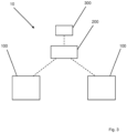
- Fig.3 shows a schematic representation of a system 10 with a plurality of measuring devices 100 according to an embodiment of the present invention.
- the system 10 comprises a total of two measuring devices 100, a control device 200 and a database 300.
- control device 200 and the database 300 are designed as independent devices external to the two measuring devices 100.
- the database 300 can also be designed as a subcomponent of the control device 200.
- the measuring devices 100 can be designed to have the same function or can be designed to carry out different measurements. Depending on the area of application, this allows the respective measuring processes to be carried out simultaneously or sequentially.
- the database 300 is shown here as a specific component of the system 10. However, it is also conceivable that the control device 200 and/or the database 300 is connected to an extended network, in particular to the Internet, and obtains relevant information directly via this network instead of storing it locally.
Landscapes
- Engineering & Computer Science (AREA)
- Physics & Mathematics (AREA)
- General Physics & Mathematics (AREA)
- Automation & Control Theory (AREA)
- General Engineering & Computer Science (AREA)
- Testing Or Calibration Of Command Recording Devices (AREA)
- Indication And Recording Devices For Special Purposes And Tariff Metering Devices (AREA)
Applications Claiming Priority (2)
| Application Number | Priority Date | Filing Date | Title |
|---|---|---|---|
| US202363453488P | 2023-03-21 | 2023-03-21 | |
| DE102023107051.7A DE102023107051A1 (de) | 2023-03-21 | 2023-03-21 | Verfahren zur steuerung einer messvorrichtung und messvorrichtung |
Publications (1)
| Publication Number | Publication Date |
|---|---|
| EP4435538A1 true EP4435538A1 (fr) | 2024-09-25 |
Family
ID=89620740
Family Applications (1)
| Application Number | Title | Priority Date | Filing Date |
|---|---|---|---|
| EP24152303.4A Pending EP4435538A1 (fr) | 2023-03-21 | 2024-01-17 | Procédé de commande d'un dispositif de mesure et dispositif de mesure |
Country Status (3)
| Country | Link |
|---|---|
| US (1) | US20240319690A1 (fr) |
| EP (1) | EP4435538A1 (fr) |
| JP (1) | JP7854466B2 (fr) |
Citations (2)
| Publication number | Priority date | Publication date | Assignee | Title |
|---|---|---|---|---|
| US20150134289A1 (en) * | 2013-11-13 | 2015-05-14 | Fluke Corporation | Profiles for streamlining calibration test |
| WO2020208300A1 (fr) * | 2019-04-12 | 2020-10-15 | Beamex Oy Ab | Procédé et agencement pour analyse de dérive à long terme |
Family Cites Families (7)
| Publication number | Priority date | Publication date | Assignee | Title |
|---|---|---|---|---|
| JPH04121622A (ja) * | 1990-09-13 | 1992-04-22 | Hitachi Ltd | プラント運転支援方法及びその装置並びにデータ表示方法 |
| JP3138908B2 (ja) * | 1995-03-20 | 2001-02-26 | 東京エレクトロン株式会社 | プローブ装置 |
| JP3542979B2 (ja) * | 2001-06-08 | 2004-07-14 | アンリツ株式会社 | 測定装置 |
| JP3930818B2 (ja) * | 2003-02-27 | 2007-06-13 | 株式会社日立製作所 | 移動端末の位置計算方法、測位システム及び位置算出装置 |
| JP4755457B2 (ja) * | 2005-07-15 | 2011-08-24 | 株式会社日立製作所 | 光ネットワーク装置及び光ネットワーク |
| JP2015128463A (ja) * | 2014-01-06 | 2015-07-16 | セイコーエプソン株式会社 | 血圧計測装置 |
| JP6574350B2 (ja) * | 2015-07-03 | 2019-09-11 | パラマウントベッド株式会社 | 報知システム及び報知装置 |
-
2024
- 2024-01-17 EP EP24152303.4A patent/EP4435538A1/fr active Pending
- 2024-03-15 JP JP2024041108A patent/JP7854466B2/ja active Active
- 2024-03-19 US US18/609,187 patent/US20240319690A1/en active Pending
Patent Citations (2)
| Publication number | Priority date | Publication date | Assignee | Title |
|---|---|---|---|---|
| US20150134289A1 (en) * | 2013-11-13 | 2015-05-14 | Fluke Corporation | Profiles for streamlining calibration test |
| WO2020208300A1 (fr) * | 2019-04-12 | 2020-10-15 | Beamex Oy Ab | Procédé et agencement pour analyse de dérive à long terme |
Also Published As
| Publication number | Publication date |
|---|---|
| JP7854466B2 (ja) | 2026-05-01 |
| JP2024137816A (ja) | 2024-10-07 |
| US20240319690A1 (en) | 2024-09-26 |
Similar Documents
| Publication | Publication Date | Title |
|---|---|---|
| DE69316511T2 (de) | Prozesssteuerung mit graphischer Schnittstelle von Attributen | |
| DE69125321T2 (de) | Vorrichtung und Verfahren zur Bestimmung der fundamentalen viskoelastischen Eigenschaften eines Materials | |
| EP3077878B1 (fr) | Procédé implémenté par ordinateur et système de surveillance automatique et de détermination de l'état de l'intégralité des étapes de processus dans une unité de traitement | |
| DE112011101738T5 (de) | Mehrstufiges Prozessmodellierungsverfahren | |
| DE102019125587A1 (de) | Zustandsbestimmungsvorrichtung und zustandsbestimmungsverfahren | |
| DE102013104203B4 (de) | Verfahren und Vorrichtung zur Bestimmung einer Restbetriebsdauer eines Messaufnehmers | |
| DE112014004154T5 (de) | Automatische Analysevorrichtung | |
| EP4435538A1 (fr) | Procédé de commande d'un dispositif de mesure et dispositif de mesure | |
| DE69212394T2 (de) | Verfahren und Vorrichtung zur Überwachung eines unter variablen Bedingungen laufenden Apparates | |
| DE102023107051A1 (de) | Verfahren zur steuerung einer messvorrichtung und messvorrichtung | |
| DE102019109258A1 (de) | Wellenformanzeigevorrichtung | |
| DE2647308C3 (de) | Verfahren und Vorrichtung zur Bestimmung der Konzentration einer Analysensubstanz | |
| EP4363844B1 (fr) | Procédé d'analyse accéléré par ia, unité d'évaluation, chromatographe en phase gazeuse, système d'analyse et produit programme informatique | |
| DE102023107075A1 (de) | Verfahren zur steuerung eines systems und system | |
| EP4435685A1 (fr) | Procédé de commande d'un système et système | |
| EP4268963B1 (fr) | Procédé et dispositif de fabrication à l'échelle industrielle d'une suspension pour une batterie | |
| DE102007059582A1 (de) | Verfahren und Vorrichtung zum Training des Bedienpersonals einer prozesstechnischen Anlage | |
| EP4435382A1 (fr) | Procédé de commande d'un dispositif de mesure et dispositif de mesure | |
| DE102023107046A1 (de) | Verfahren zur steuerung einer messvorrichtung und messvorrichtung | |
| EP3928033B1 (fr) | Procédé de commande d'une turbine à gaz | |
| EP4435691A1 (fr) | Procédé de commande d'un dispositif de mesure et dispositif de mesure | |
| EP4435381A1 (fr) | Procédé de commande d'un dispositif de mesure, dispositif de mesure et système | |
| DE102023107031A1 (de) | Verfahren zur steuerung einer messvorrichtung und messvorrichtung | |
| DE102023107027A1 (de) | Verfahren zur steuerung einer messvorrichtung, messvorrichtung und system | |
| WO2009115214A1 (fr) | Procédé de post-étalonnage de capteurs et d'étalonnage de capteurs additionnels |
Legal Events
| Date | Code | Title | Description |
|---|---|---|---|
| PUAI | Public reference made under article 153(3) epc to a published international application that has entered the european phase |
Free format text: ORIGINAL CODE: 0009012 |
|
| STAA | Information on the status of an ep patent application or granted ep patent |
Free format text: STATUS: THE APPLICATION HAS BEEN PUBLISHED |
|
| AK | Designated contracting states |
Kind code of ref document: A1 Designated state(s): AL AT BE BG CH CY CZ DE DK EE ES FI FR GB GR HR HU IE IS IT LI LT LU LV MC ME MK MT NL NO PL PT RO RS SE SI SK SM TR |
|
| STAA | Information on the status of an ep patent application or granted ep patent |
Free format text: STATUS: REQUEST FOR EXAMINATION WAS MADE |
|
| 17P | Request for examination filed |
Effective date: 20250227 |
|
| STAA | Information on the status of an ep patent application or granted ep patent |
Free format text: STATUS: EXAMINATION IS IN PROGRESS |
|
| 17Q | First examination report despatched |
Effective date: 20260309 |