EP4435541A1 - Flux de travail pour le paramétrage efficace d'une commande numérique - Google Patents
Flux de travail pour le paramétrage efficace d'une commande numérique Download PDFInfo
- Publication number
- EP4435541A1 EP4435541A1 EP23164078.0A EP23164078A EP4435541A1 EP 4435541 A1 EP4435541 A1 EP 4435541A1 EP 23164078 A EP23164078 A EP 23164078A EP 4435541 A1 EP4435541 A1 EP 4435541A1
- Authority
- EP
- European Patent Office
- Prior art keywords
- spindle
- spindle drive
- computing device
- drive
- numerical control
- Prior art date
- Legal status (The legal status is an assumption and is not a legal conclusion. Google has not performed a legal analysis and makes no representation as to the accuracy of the status listed.)
- Granted
Links
Images


Classifications
-
- G—PHYSICS
- G05—CONTROLLING; REGULATING
- G05B—CONTROL OR REGULATING SYSTEMS IN GENERAL; FUNCTIONAL ELEMENTS OF SUCH SYSTEMS; MONITORING OR TESTING ARRANGEMENTS FOR SUCH SYSTEMS OR ELEMENTS
- G05B19/00—Program-control systems
- G05B19/02—Program-control systems electric
- G05B19/18—Numerical control [NC], i.e. automatically operating machines, in particular machine tools, e.g. in a manufacturing environment, so as to execute positioning, movement or co-ordinated operations by means of program data in numerical form
- G05B19/416—Numerical control [NC], i.e. automatically operating machines, in particular machine tools, e.g. in a manufacturing environment, so as to execute positioning, movement or co-ordinated operations by means of program data in numerical form characterised by control of velocity, acceleration or deceleration
-
- G—PHYSICS
- G05—CONTROLLING; REGULATING
- G05B—CONTROL OR REGULATING SYSTEMS IN GENERAL; FUNCTIONAL ELEMENTS OF SUCH SYSTEMS; MONITORING OR TESTING ARRANGEMENTS FOR SUCH SYSTEMS OR ELEMENTS
- G05B19/00—Program-control systems
- G05B19/02—Program-control systems electric
- G05B19/18—Numerical control [NC], i.e. automatically operating machines, in particular machine tools, e.g. in a manufacturing environment, so as to execute positioning, movement or co-ordinated operations by means of program data in numerical form
- G05B19/182—Numerical control [NC], i.e. automatically operating machines, in particular machine tools, e.g. in a manufacturing environment, so as to execute positioning, movement or co-ordinated operations by means of program data in numerical form characterised by the machine tool function, e.g. thread cutting, cam making, tool direction control
-
- G—PHYSICS
- G05—CONTROLLING; REGULATING
- G05B—CONTROL OR REGULATING SYSTEMS IN GENERAL; FUNCTIONAL ELEMENTS OF SUCH SYSTEMS; MONITORING OR TESTING ARRANGEMENTS FOR SUCH SYSTEMS OR ELEMENTS
- G05B19/00—Program-control systems
- G05B19/02—Program-control systems electric
- G05B19/18—Numerical control [NC], i.e. automatically operating machines, in particular machine tools, e.g. in a manufacturing environment, so as to execute positioning, movement or co-ordinated operations by means of program data in numerical form
- G05B19/408—Numerical control [NC], i.e. automatically operating machines, in particular machine tools, e.g. in a manufacturing environment, so as to execute positioning, movement or co-ordinated operations by means of program data in numerical form characterised by data handling or data format, e.g. reading, buffering or conversion of data
- G05B19/4083—Adapting program, configuration
-
- G—PHYSICS
- G05—CONTROLLING; REGULATING
- G05B—CONTROL OR REGULATING SYSTEMS IN GENERAL; FUNCTIONAL ELEMENTS OF SUCH SYSTEMS; MONITORING OR TESTING ARRANGEMENTS FOR SUCH SYSTEMS OR ELEMENTS
- G05B2219/00—Program-control systems
- G05B2219/30—Nc systems
- G05B2219/35—Nc in input of data, input till input file format
- G05B2219/35356—Data handling
-
- G—PHYSICS
- G05—CONTROLLING; REGULATING
- G05B—CONTROL OR REGULATING SYSTEMS IN GENERAL; FUNCTIONAL ELEMENTS OF SUCH SYSTEMS; MONITORING OR TESTING ARRANGEMENTS FOR SUCH SYSTEMS OR ELEMENTS
- G05B2219/00—Program-control systems
- G05B2219/30—Nc systems
- G05B2219/43—Speed, acceleration, deceleration control ADC
- G05B2219/43006—Acceleration, deceleration control
-
- G—PHYSICS
- G05—CONTROLLING; REGULATING
- G05B—CONTROL OR REGULATING SYSTEMS IN GENERAL; FUNCTIONAL ELEMENTS OF SUCH SYSTEMS; MONITORING OR TESTING ARRANGEMENTS FOR SUCH SYSTEMS OR ELEMENTS
- G05B2219/00—Program-control systems
- G05B2219/30—Nc systems
- G05B2219/49—Nc machine tool, till multiple
- G05B2219/49079—Control cutting torque, force
Definitions
- the present invention is further based on a computer program which comprises machine code which can be processed by a computing device which can be coupled to at least one numerical control, wherein the processing of the machine code by the computing device causes the computing device to carry out such a parameterization method.
- the present invention is further based on a computing device which can be coupled to at least one numerical control and is programmed with such a computer program so that it carries out such a parameterization method during operation.
- the spindle drive there are further requirements for the operation of the spindle drive.
- some applications and cutting qualities require very high spindle drive speeds, for example when working with a high path feed in order to increase the productivity of the machine tool, or because high surface qualities must be achieved.
- the acceleration time is important for the achievable productivity, but also the acceleration time required to run up the spindle drive to the corresponding speed (i.e. the working speed).
- the data sheet of the motor manufacturer must be interpreted for the drive motor used. Furthermore, it must be determined which electrical boundary conditions exist on the electrical equipment, in particular which options the converter provides.
- the machine tool must be programmed so that a run-up test can be carried out. The machine tool must be prepared for the run-up test. For example, the spindle must be warmed up and the lubrication of the spindle must be checked. The run-up test must be carried out. The time until the working speed is reached must be recorded.
- the object of the present invention is to create possibilities by means of which the cycle time, i.e. the sum of acceleration time and machining time, and thus the productivity of the machine tool, can also be optimized in a permissible manner by other operators.
- the command to briefly control the spindle drive is known as such.
- the associated loading of the spindle drive and the recording of the corresponding spindle data are also known as such.
- Such procedures are particularly known in the context of so-called auto servo tuning. Based on this, determining the moment of inertia of the spindle (including the spindle drive) only requires knowledge of the effective torque and the resulting acceleration of the spindle.
- the parameters that the computer retrieves from the spindle drive converter determine - at least in part - what current and what power the converter can supply to the drive motor and what torque - usually speed-dependent - the drive motor can apply to the spindle. Otherwise, the parameters can be determined as required.
- the parameters usually include the current limit of the semiconductor switches, the power limit of the converter, the torque limit of the spindle drive, the torque limit of the spindle and/or the conversion factor by means of which a motor current fed into the spindle drive by the converter can be converted into a torque acting in the spindle drive.
- the motor data that the computer retrieves from the spindle drive converter can also be determined as required, provided that they allow the desired determinations.
- the motor data of the spindle drive drive motor often includes the motor type, the rated speed and/or the design torque of the drive motor.
- the motor type determines in particular whether the drive motor is a synchronous machine or an asynchronous machine, etc.
- the rated speed is the speed at which the drive motor reaches its rated power.
- the design torque is the torque up to which the drive motor can be loaded without suffering damage.
- the process data can include additional data in addition to the process moment. However, this is not mandatory.
- the computer can therefore determine the thermal losses that occur in the spindle drive during certain operating modes. This also makes it possible to determine permissible combinations of acceleration times, process torques and machining times, i.e. combinations in which the average thermal losses do not exceed a predetermined loss limit.
- the computer can then offer these combinations to the operator for selection. Based on the operator's selection, the limit values to be observed by the numerical control and the spindle drive can then be determined.
- the limit values to be observed by the numerical control and the spindle drive can include, in particular, the maximum current and power that the converter supplies to the drive motor.
- the limit values to be observed by the numerical control and the spindle drive can include the maximum torque applied by the spindle drive and a maximum acceleration of the spindle drive.
- friction occurring in the spindle can be neglected.
- the Calculation device the friction occurring in the spindle as part of determining the possible acceleration times.
- it is not - at least as a rule - about the thermal effects caused by the friction as such, but about the (negative) effect of the friction on the acceleration.
- it is usually not necessary to take friction into account, since the friction is already included in the required process moment as such.
- additional consideration can also be made here if necessary.
- the characteristics of the computing device can be specified by the operator.
- the computing device it is possible for the computing device to determine the characteristics of the friction occurring in the spindle using measured operating data of the spindle.
- the computing device receives inertia-relevant variables from the operator, which the computing device takes into account when determining the resulting moment of inertia in addition to the moment of inertia of the spindle including the spindle drive.
- the additional variables can in particular be a moment of inertia of a tool and/or an offset provided for safety reasons.
- the process data include the machining time in addition to the process moment.
- the computing device preferably determines the achievable acceleration time for values around the process moment and/or the machining time and outputs it to the operator.
- the process data does not include the machining time.
- the computing device determines the minimum possible acceleration time and, for the minimum possible acceleration time, the minimum required machining time as a function of the process torque occurring or, conversely, the maximum permissible process torque as a function of the machining time and outputs these value pairs to the operator.
- the object is further achieved by a computer program having the features of claim 9.
- the processing of the computer program by the computing device causes the computing device to carry out a parameterization method according to the invention.
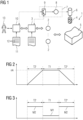
- a machine tool 1 has a number of position-controlled axes 2. As a rule, several position-controlled axes 2 are present. However, this is not necessary in all cases.
- the position-controlled axes 2 are controlled by a numerical control 3. In normal operation, the numerical control 3 controls the position-controlled axes 2, in the case of several position-controlled axes 2, coordinated accordingly.
- the associated part program is in FIG 1 indicated, but not provided with a reference symbol.
- the spindle 6 has a spindle drive 7, by means of which the spindle 6 is rotated.
- the spindle drive 7 has a drive motor 8, which is supplied with power via a converter 9. By supplying the drive motor 8 with power, the spindle drive 7 generates a torque.
- Normal operation is the operation of the numerical control during which the workpiece is being machined. Normal operation therefore represents productive operation.
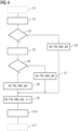
- the machining of the workpiece 5 is carried out according to FIG 2 intermittently.
- phases of processing alternate with phases of non-processing.
- Each processing phase has a respective processing time T1.
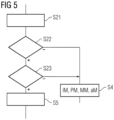
- the spindle drive 7 applies the spindle 6 according to FIG 3 with a respective process torque M1.
- the associated run-up phase has a run-up time T2'.
- An acceleration torque M2 is effective for acceleration.
- the spindle 6 and the spindle drive 7 are also controlled by the numerical control 3.
- the working speed nA can be fixed or specified to the numerical control 3, for example as part of the workflow explained below or in another way.
- a braking time T2" is required for braking.
- the sequence of acceleration phase, machining phase and braking phase is carried out iteratively.
- the tool 4 is often changed between braking and acceleration.
- the machining phases are therefore often each carried out with a separate tool 4.
- the machining times T1 can vary from machining phase to machining phase under certain circumstances. Where reference is made below to the machining time T1, this refers to the minimum value of the machining times T1.
- the process torque M1 can also vary in a similar way, both within the respective machining phase and from machining phase to machining phase. Where reference is made below to the process torque M1, this refers to the maximum value of the process torque M1.
- the acceleration time T2' is essentially determined by the torque applied to the spindle 6 during the acceleration time T2', i.e. the acceleration torque M2.
- the acceleration torque M2 can be constant or vary. As a rule, however, the acceleration torque M2 is always selected to be as large as is just possible given the operating conditions of the spindle drive 7. The same applies to braking during the braking time T2".
- the associated braking torque is generally the same amount as the acceleration torque M2.
- the reference symbol M2 is therefore also used for the braking torque or generally only the acceleration torque M2 is referred to.
- An acceleration time T2 is directly linked to the acceleration torque M2.
- the acceleration time T2 only includes the acceleration time T2'. If necessary, the acceleration time T2 can also include the braking time T2", i.e. the sum of the acceleration time T2' and the braking time T2".
- the acceleration torque M2 is directly coupled to a maximum acceleration aM with which the spindle 6 can be operated.
- the maximum acceleration aM in turn influences the acceleration time T2' and the braking time T2" and thus in any case the acceleration time T2.
- the acceleration torque M2 is in turn dependent on limit values IM, PM, MM, aM, which are maintained by the numerical control 3 and the spindle drive 7 and here in particular by the converter 9. The determination of these limit values IM, PM, MM, aM is the core subject of the present invention.
- the determination of the limit values IM, PM, MM, aM is carried out in a computing device 10.
- the computing device 10 is coupled at least to the numerical control 3. If necessary, the computing device 10 can, as in FIG 1 indicated by dashed lines, also be coupled to the converter 9. If the computing device 10 is not directly coupled to the converter 9, an indirect coupling takes place via the numerical control 3. This is also shown in FIG 1 indicated by dashed lines.
- the computing device 10 is programmed with a computer program 11.
- the computer program 11 includes machine code 12 that can be processed by the computing device 10. Due to the programming of the computing device 10 with the computer program 11 or the processing of the machine code 12 by the computing device 10, the computing device 10 carries out a parameterization process.
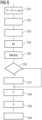
- the parameterization process and the associated workflow are described below in connection with FIG 4 and the other FIGS.
- the computing device 10 is first coupled to the numerical control 3 and, if necessary, also to the converter 9 in a step S1.
- the coupling is generally not carried out exclusively by the computing device 10, but at least partially by an operator 13 (see FIG 1 ).
- the step S1 is therefore in FIG 4 only shown in dashed lines.
- a higher-level workflow is started.
- the start can either be carried out automatically by the computing device 10 or based on an input from the operator 13.
- the higher-level workflow includes the part of the workflow according to the invention, but also includes other issues.
- step S3 the computing device 10 decides based on inputs from the operator 13 whether the workflow according to the invention should be carried out or not.
- step S3 is described in connection with FIG 5 be explained.
- step S4 the computing device 10 determines standard values for the limit values IM, PM, MM, aM to be observed.
- the standard values are generally based on the assumption of the so-called S1 operation of the spindle drive 7, i.e. the permanent operation of the spindle drive 7 (continuous load).
- Step S4 can be implemented in a manner known per se. As such, it is not the subject of the present invention. For the sake of clarity, it should be explicitly pointed out that the S1 operation of the spindle drive 7 does not correspond to step S1 of the workflow, despite being designated as "S1".
- the computing device 10 carries out activities in a step S5 which are always carried out within the scope of the workflow according to the invention.
- the step S5 is carried out in conjunction with FIG 6 be explained.
- the computing device 10 asks the operator 13 whether the machining process to which the ramp-up time T2 is to be adjusted is a machining process known to the operator 13.
- the computing device 10 goes to a step S7, in the case of a known machining process to a step S8.
- the steps S7 and S8 are carried out in conjunction with the FIG 10 and 11 explained.
- steps S5 to S8 the individualized determination of the limit values IM, PM, MM, aM to be observed takes place.
- Steps S5 to S8 represent the core of the present invention.
- step S9 the computing device 10 transmits the values determined in one of steps S4, S7 and S8 as limit values IM, PM, MM, aM to be observed during operation of the numerical control 3 to the numerical control 3 and, if necessary, also to the converter 9.
- step S10 the computing device 10 ends the workflow.
- the parameterization process is completed with the execution of step S10.
- the computing device 10 is only decoupled from at least the numerical control 3 and possibly also the converter 9 in a step S11.
- the decoupler is generally not carried out exclusively by the computing device 10, but at least partially by the operator 13.
- the step S11 is therefore analogous to the step S1 in FIG 4 only shown in dashed lines.
- step S3 of FIG 4 explained in more detail.
- the computing device 10 starts a query sequence in a step S21.
- the query in step S23 may include, for example, whether the machine tool is to be used in mold making and/or whether fine contours and high productivity are desired.
- step S5 of FIG 4 explained in more detail.
- the computing device 10 selects the goal of the workflow based on an input from the operator 13, namely to minimize the cycle time (that is the sum of the processing time T1 and the acceleration time T2).
- the so-called S6 operation of the spindle drive 7 is selected, i.e. the alternating operation with high-load phases and recovery phases.
- the high-load phases correspond to the run-up phases and/or the braking phases, the recovery phases to the processing phases.
- the S6 operation of the spindle drive 7 does not correspond to step S6 of the workflow despite being designated as "S6".
- the situation is analogous to the relationship between the S1 operation of the spindle drive 7 and step S1.
- a step S32 the computing device 10 transmits to the numerical control 3 a command for (briefly) controlling the spindle drive 7, so that the spindle drive 7 is subjected to a drive torque.
- the computing device 10 receives measurement data from the numerical control 3.
- the measurement data are recorded by the numerical control 3 during the short-term control.
- the measurement data are determined in such a way that that the acceleration of the spindle 6 caused during the brief activation can be determined from them.
- the measurement data can include the rotational position or the speed (or data characteristic thereof) as a function of time. If necessary, they can also include, for example, the torque generated by the drive motor 8 (or data characteristic thereof).
- steps S32 and S33 as such are known to those skilled in the art.
- the computing device 10 determines a moment of inertia ⁇ of the spindle 6 including the spindle drive 7, taking into account the measurement data.
- the computing device 10 also knows the torque generated by the drive motor 8 - either a priori or on the basis of the measurement data - so that in conjunction with the acceleration caused (the acceleration caused can be determined from the measurement data), the moment of inertia ⁇ can be easily determined.
- a step S35 the computing device 10 determines a resulting moment of inertia ⁇ R.
- the resulting moment of inertia ⁇ R depends on the moment of inertia ⁇ determined in step S34. In the simplest case, the resulting moment of inertia ⁇ R is identical to the moment of inertia ⁇ determined in step S34. However, it is also possible to determine a different value. This will be discussed later in connection with FIG 7 be explained.
- step S36 the computing device 10 asks the operator 13 whether the occurring friction should be explicitly taken into account. If this is the case, the computing device 10 receives friction data corresponding to a step S37. Otherwise, step S37 is skipped. Possible embodiments of step S37 will be discussed in connection with the FIGS 8 and 9 be explained.
- the computing device 10 retrieves parameters P from the converter 9 of the spindle drive 7, which describe the maximum possible operating limits of the converter 9.
- the parameters P can be retrieved directly from the converter 9, provided that there is a corresponding coupling between the computing device 10 and the converter 9. Alternatively, they can be retrieved indirectly via the numerical control 3.
- a step S39 the computing device 10 retrieves motor data D from the converter 9 of the spindle drive 7, from which the maximum possible torque of the spindle drive 7 can be determined as a function of the speed of the drive motor 8. Analogous to the procedure for the parameters P, a direct retrieval from the converter 9 or an indirect retrieval via the numerical control 3 can alternatively take place.
- step S40 the computing device 10 determines a torque characteristic curve for the drive motor 8. It therefore determines the maximum possible torque as a function of the speed. The determination is made using the parameters P and the motor data D.
- the implementation of step S40 is known as such to those skilled in the art.
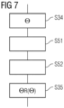
- step S35 of FIG 6 The following is in connection with FIG 7 a possible embodiment of step S35 of FIG 6 explained.
- steps S51 and S52 there is a step S51 and/or a step S52.
- the computing device 10 receives inertia-relevant variables from the operator 13.
- the computing device 10 takes these variables into account when determining the resulting moment of inertia ⁇ R in addition to the moment of inertia ⁇ determined in step S34.
- a moment of inertia of the tool 4 can be specified in step S51.
- the largest moment of inertia is usually specified here.
- step S52 a (freely selectable) offset can be specified, a kind of reserve for all eventualities, so to speak.
- the resulting moment of inertia ⁇ R is the sum of the moment of inertia ⁇ determined in step S34 and the values specified in steps S51 and S52.
- step S37 is implemented by a query to the operator 13.
- the operator 13 thus provides the computing device 10 with characteristic data which are characteristic of the friction occurring in the spindle 6.
- step S37 is implemented in the form of steps S61 to S63.
- step S61 the computing device 10 initiates a measuring process in the numerical control 3 for measuring the operating data of the spindle 6.
- the operating data are determined in such a way that characteristic data for the friction occurring in the spindle 6 can be determined using the operating data.
- step S62 the computing device 10 receives the operating data from the numerical control 3.
- step S63 the computing device 10 determines the characteristic data for the friction.
- Steps S61 to S63 can be implemented, for example, in such a way that rotation of the spindle drive 7 is initiated at a certain speed and the torque required to maintain this speed is recorded. Since in the case of complete lack of friction the torque to maintain a certain speed is 0, the required torque must be due to friction. If necessary, this procedure can be repeated for several speeds. There are also other possibilities for determining friction.
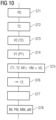
- step S7 of FIG 5 The following is in connection with FIG 10 a possible embodiment of step S7 of FIG 5 explained.
- the computing device 10 receives process data PD from the operator 13 in a step S71.
- the process data PD comprise the process moment M1, i.e. in the sense of the present invention the maximum occurring value of the process moment M1. Due to the fact that in the procedure of FIGURE 10 Assuming that the machining process is not known, no further data is usually specified in step S71. In particular, the process data PD does not include the machining time T1. However, it is possible that the working speed nA is also specified in step S71.
- the computing device 10 determines the minimum possible acceleration time T2 and the associated required currents (which the converter 9 supplies to the drive motor 8) and torques (which the drive motor 8 generates).
- the acceleration of spindle 6 is simulated iteratively in small time steps with respective adjustment of the achieved speed until the working speed nA is reached.
- the change in the speed from time step to time step includes the resulting moment of inertia ⁇ R of the respective time step and - if taken into account - the friction occurring in the spindle 6.
- the friction, if taken into account, therefore has an effect on the possible acceleration time T2'.
- the computing device 10 can also determine the braking time T2".
- the computing device 10 determines the thermal losses V2 occurring during the determined acceleration time T2. It is often sufficient to take into account only the copper losses in the winding of the drive motor 8. If necessary, the iron losses can also be taken into account. If necessary, the losses occurring in the converter 9 can also be determined in a separate calculation.
- steps S72 and S73 can be repeated while limiting the current to values below the current limit, so that the corresponding acceleration time T2 can be determined for certain maximum currents.
- a step S74 the computing device 10 determines the associated losses V1 for the process torque M1.
- the calculation of the losses V1 takes into account the conversion factor, possibly the motor type and possibly the working speed nA. If the process torque M1 does not yet take friction into account, this can be taken into account if necessary.
- the step S74 is not only carried out for the process torque M1 specified in step S71, but also for some nearby values above and/or below it. This allows the associated losses V1 to be determined for several process torques M1.
- the computing device 10 determines combinations of acceleration times T2, process moments M1 and processing times T1 whose average thermal losses VM must not exceed a predetermined loss limit VG.
- the acceleration time T2 is fixed because it is determined to be as small as possible.
- the associated thermal losses V2 result from the corresponding operation of the spindle drive 7 and are therefore also fixed.
- the thermal losses V1 are determined by the process torque M1 (plus friction if necessary) and are therefore also fixed. This leaves a single value that can still be varied, namely the processing time T1.
- the computing device 10 can therefore determine the minimum required processing time T1 for the various assumed process torques M1, i.e. the minimum required processing time T1 as a function of the occurring process torque M1.
- the computing device 10 offers the determined combinations of acceleration times T2, process torques M1 and processing times T1 - i.e. the permissible combinations - to the operator 13 for selection.
- the computing device 10 receives a selection of such a combination from the operator 13.
- the computing device 10 determines, based on the selection of the operator 13, the limit values IM, PM, MM, aM to be observed.
- the determined limit values IM, PM, MM, aM can in particular include the current IM and the power PM which the converter 9 supplies to the drive motor.
- the limit values to be observed by the numerical control 3 and the spindle drive 7 can include the maximum torque MM applied by the spindle drive 7 and a maximum acceleration aM of the spindle drive 7.
- step S8 of FIG 5 The following is in connection with FIG 11 a possible embodiment of step S8 of FIG 5 explained.
- the computing device 10 receives the process data PD from the operator 13 in a step S81.
- the step S81 of FIGURE 11 corresponds in content to step S71 of FIGURE 10 . Due to the fact that the approach of FIGURE 11 However, assuming that the machining process is known, the machining time T1 can also be specified in step S81.
- step S82 the computing device 10 determines a possible start-up time T2 and the associated required currents (which the converter 9 supplies to the drive motor 8) and torques (which the drive motor 8 generates) for a specific maximum current.
- step S82 corresponds to FIGURE 11 with step S72 of FIGURE 10 The only difference is that the permissible current does not necessarily have to be the maximum value.
- a step S83 the computing device 10 determines the thermal losses V2 occurring during the determined start-up time T2.
- the step S83 of FIGURE 11 corresponds in content to step S73 of FIGURE 10 .
- Steps S82 and S83 are repeated while limiting the current to different values below the current limit.
- a step S84 the computing device 10 determines for the process moment M1 and some nearby values above and/or below the corresponding losses V1.
- the step S84 of FIGURE 11 corresponds in content to step S74 of FIGURE 10 .
- a step S85 the computing device 10 determines combinations of acceleration times T2, process moments M1 and processing times T1 whose average thermal losses VM do not exceed a predetermined loss limit VG.
- the respective average thermal loss VM is obtained in the same way as already for FIGURE 10
- the acceleration time T2 is not fixed.
- the processing time T1 is fixed because it is specified in step S81. Strictly speaking, a single value could be determined in step S85, namely the achievable acceleration time T2 at which the loss limit VG is just met.
- a step S86 the computing device 10 offers the determined combinations of acceleration times T2, process moments M1 and processing times T1 - i.e. the permissible combinations - to the operator 13 for selection.
- a step S87 the computing device 10 receives a selection of such a combination from the operator 13.
- the computing device 10 determines the limit values IM, PM, MM, aM to be observed based on the selection of the operator 13.
- the steps S86 to S88 of FIGURE 11 correspond to steps S76 to S78 of FIGURE 10 .
- a numerical control 3 iteratively accelerates a spindle 6 during an acceleration time T2 by means of a spindle drive 7 and, during a subsequent processing time T1, machines a workpiece 5 by means of a respective tool 4 held in the spindle 6.
- the spindle drive 7 rotates the tool 4 during the processing time T1 at a working speed nA and applies a process torque M1 to it.
- the spindle drive 7 has a converter 9 which supplies a drive motor 8 of the spindle drive 7 with power.
- limit values IM, PM, MM, aM to be observed by the numerical control 3 and the spindle drive 7 are determined in a computing device 10 coupled to the numerical control 3 as part of a workflow and transmitted to the numerical control 3 and the converter 9.
- the computing device 10 transmits a command to the numerical control 3 for briefly controlling the spindle drive 7, receives from the numerical control 3 an associated application of a drive torque to the spindle drive 7 and data on an associated acceleration of the spindle 6, and uses this to determine a moment of inertia ⁇ of the spindle 6 including the spindle drive 7.
- the computing device 10 retrieves from the converter 9 parameters P, which describe the maximum possible operating limits () of the converter 9, and motor data D of the drive motor 8, from which the maximum possible torque of the spindle drive 7 can be determined as a function of the speed of the drive motor 8.
- the computing device 10 receives process data PD from an operator 13, which includes at least the process torque M1.
- the computing device 10 determines the associated required currents and torques and the thermal losses occurring in the spindle drive 7 for possible acceleration times T2, taking into account the working speed nA, a resulting moment of inertia ⁇ R determined taking into account the moment of inertia ⁇ of the spindle 6 including the spindle drive 7, the parameters P and the motor data D and the process data PD.
- the computing device 10 determines combinations of acceleration times T2, process moments M1 and machining times T1 whose average thermal losses VM do not exceed a predetermined loss limit VG, offers the operator 13 the determined combinations for selection, accepts a selection of such a combination from the operator 13 and determines the limit values IM, PM, MM, aM to be observed based on this selection.
- the limit values IM, PM, MM, aM to be observed can be optimized by an operator 13 who is not an expert, taking into account the alternating sequence of acceleration times T2 and processing times T1.
- the current limitations that must be taken into account when operating the spindle 6 and the spindle drive 7 can be read from the numerical control 3 and the converter 9 and taken into account when determining the limit values IM, PM, MM, aM to be observed.
- the torque characteristic can also be determined from the parameters P and motor data D stored in the converter 9. Overloading of the spindle 6 and the spindle drive 7 (including the drive motor 8 and the converter 9) can be reliably avoided.
- the parameterization method according to the invention is particularly advantageous when the working speed nA has a high value, so that the acceleration time T2 is also correspondingly long.
Landscapes
- Engineering & Computer Science (AREA)
- Human Computer Interaction (AREA)
- Manufacturing & Machinery (AREA)
- Physics & Mathematics (AREA)
- General Physics & Mathematics (AREA)
- Automation & Control Theory (AREA)
- Numerical Control (AREA)
Priority Applications (3)
| Application Number | Priority Date | Filing Date | Title |
|---|---|---|---|
| EP23164078.0A EP4435541B1 (fr) | 2023-03-24 | 2023-03-24 | Flux de travail pour le paramétrage efficace d'une commande numérique |
| CN202410336412.6A CN118689164A (zh) | 2023-03-24 | 2024-03-22 | 用于高效参数化数控装置的工作流 |
| US18/613,911 US12704824B2 (en) | 2023-03-24 | 2024-03-22 | Workflow for efficient parameterization of a numerical control |
Applications Claiming Priority (1)
| Application Number | Priority Date | Filing Date | Title |
|---|---|---|---|
| EP23164078.0A EP4435541B1 (fr) | 2023-03-24 | 2023-03-24 | Flux de travail pour le paramétrage efficace d'une commande numérique |
Publications (3)
| Publication Number | Publication Date |
|---|---|
| EP4435541A1 true EP4435541A1 (fr) | 2024-09-25 |
| EP4435541C0 EP4435541C0 (fr) | 2026-05-27 |
| EP4435541B1 EP4435541B1 (fr) | 2026-05-27 |
Family
ID=85726934
Family Applications (1)
| Application Number | Title | Priority Date | Filing Date |
|---|---|---|---|
| EP23164078.0A Active EP4435541B1 (fr) | 2023-03-24 | 2023-03-24 | Flux de travail pour le paramétrage efficace d'une commande numérique |
Country Status (3)
| Country | Link |
|---|---|
| US (1) | US12704824B2 (fr) |
| EP (1) | EP4435541B1 (fr) |
| CN (1) | CN118689164A (fr) |
Citations (2)
| Publication number | Priority date | Publication date | Assignee | Title |
|---|---|---|---|---|
| EP3518051A1 (fr) * | 2018-01-26 | 2019-07-31 | Siemens Aktiengesellschaft | Identification d'une stratégie d'optimisation du fonctionnement d'une machine d'usinage |
| EP4130902A1 (fr) * | 2021-08-05 | 2023-02-08 | Siemens Aktiengesellschaft | Identification des paramètres du modèle d'une machine de production ainsi que leur application pour déterminer des trajectoires optimisées |
Family Cites Families (1)
| Publication number | Priority date | Publication date | Assignee | Title |
|---|---|---|---|---|
| JP6542713B2 (ja) * | 2016-06-09 | 2019-07-10 | ファナック株式会社 | 異常負荷検出の閾値を学習する機械学習器,数値制御装置および機械学習方法 |
-
2023
- 2023-03-24 EP EP23164078.0A patent/EP4435541B1/fr active Active
-
2024
- 2024-03-22 CN CN202410336412.6A patent/CN118689164A/zh active Pending
- 2024-03-22 US US18/613,911 patent/US12704824B2/en active Active
Patent Citations (2)
| Publication number | Priority date | Publication date | Assignee | Title |
|---|---|---|---|---|
| EP3518051A1 (fr) * | 2018-01-26 | 2019-07-31 | Siemens Aktiengesellschaft | Identification d'une stratégie d'optimisation du fonctionnement d'une machine d'usinage |
| EP4130902A1 (fr) * | 2021-08-05 | 2023-02-08 | Siemens Aktiengesellschaft | Identification des paramètres du modèle d'une machine de production ainsi que leur application pour déterminer des trajectoires optimisées |
Also Published As
| Publication number | Publication date |
|---|---|
| US20240319701A1 (en) | 2024-09-26 |
| EP4435541C0 (fr) | 2026-05-27 |
| CN118689164A (zh) | 2024-09-24 |
| EP4435541B1 (fr) | 2026-05-27 |
| US12704824B2 (en) | 2026-08-11 |
Similar Documents
| Publication | Publication Date | Title |
|---|---|---|
| DE102009007437B4 (de) | Reitstock-Regelungsvorrichtung | |
| DE69922952T2 (de) | Verfahren und vorrichtung zur numerischen steuerung einer werkzeugmaschine | |
| EP2553802B1 (fr) | Procédé de commande d'un point de fonctionnement optimal sur une machine synchrone et machine synchrone alimentée par un convertisseur | |
| DE102018006157B4 (de) | Werkzeugmaschinensystem | |
| DE102014005198B4 (de) | Motorsteuerung mit Stromausfallfeststellung | |
| DE102014010314B4 (de) | Motorsteuerung einer Werkzeugmaschine mit Stromausfallschutz | |
| DE19882519B4 (de) | Synchronisationssteuergerät für einen Servomotor | |
| DE102015200870A1 (de) | Gerät zum Erzeugen eines NC-Programms, das eine Leistungseinsparung berücksichtigt | |
| DE102014004093A1 (de) | Motorsteuervorrichtung zur synchronen Steuerung mehrerer Motoren | |
| DE102010025960B4 (de) | Steuervorrichtung für eine Pressmaschine | |
| DE102009054829A1 (de) | Verfahren und Einrichtung zum Betrieb einer Maschine aus der Automatisierungstechnik | |
| DE102013000856A1 (de) | Motorsteuervorrichtung, die einen Drehmomentbefehl in Abhängigkeit vom Eingangsstrom oder der Eingangsleistung begrenzt | |
| DE112012006087T5 (de) | Steuervorrichtung und Bearbeitungsverfahren für elektrische Drahtentladungsmaschine | |
| EP4130902A1 (fr) | Identification des paramètres du modèle d'une machine de production ainsi que leur application pour déterminer des trajectoires optimisées | |
| DE102020002087A1 (de) | Steuervorrichtung einer Werkzeugmaschine mit einer Spindelachse und einer Vorschubachse | |
| DE102018202105B4 (de) | Numerische steuerung für werkzeugmaschine | |
| EP2874547B1 (fr) | Dispositif et procédé de commande d'entraînement d'un système chirurgical à moteur | |
| DE102020208478A1 (de) | Servosteuerung | |
| DE102018217540A1 (de) | Motorsteuervorrichtung | |
| DE112021001850B4 (de) | Steuervorrichtung | |
| EP2192465A1 (fr) | Réglage d'un entraînement asservi doté d'une détermination dynamique de la dynamique de l'axe conducteur | |
| EP3804118B1 (fr) | Fonctionnement optimisé d'une machine à plusieurs commandes | |
| EP0223101B1 (fr) | Dispositif de commande pour un moteur d'entraînement à courant continu à excitation séparée et procédé pour commander un moteur d'entraînement à courant continu d'une machine à imprimer | |
| EP3309635A1 (fr) | Détermination d'un programme de pièce optimisé pour une machine de traitement respective | |
| EP3367185A1 (fr) | Système de moteur et sa évaluation |
Legal Events
| Date | Code | Title | Description |
|---|---|---|---|
| PUAI | Public reference made under article 153(3) epc to a published international application that has entered the european phase |
Free format text: ORIGINAL CODE: 0009012 |
|
| STAA | Information on the status of an ep patent application or granted ep patent |
Free format text: STATUS: THE APPLICATION HAS BEEN PUBLISHED |
|
| AK | Designated contracting states |
Kind code of ref document: A1 Designated state(s): AL AT BE BG CH CY CZ DE DK EE ES FI FR GB GR HR HU IE IS IT LI LT LU LV MC ME MK MT NL NO PL PT RO RS SE SI SK SM TR |
|
| STAA | Information on the status of an ep patent application or granted ep patent |
Free format text: STATUS: REQUEST FOR EXAMINATION WAS MADE |
|
| 17P | Request for examination filed |
Effective date: 20250324 |
|
| GRAP | Despatch of communication of intention to grant a patent |
Free format text: ORIGINAL CODE: EPIDOSNIGR1 |
|
| STAA | Information on the status of an ep patent application or granted ep patent |
Free format text: STATUS: GRANT OF PATENT IS INTENDED |
|
| INTG | Intention to grant announced |
Effective date: 20260219 |
|
| GRAS | Grant fee paid |
Free format text: ORIGINAL CODE: EPIDOSNIGR3 |
|
| GRAA | (expected) grant |
Free format text: ORIGINAL CODE: 0009210 |
|
| STAA | Information on the status of an ep patent application or granted ep patent |
Free format text: STATUS: THE PATENT HAS BEEN GRANTED |
|
| AK | Designated contracting states |
Kind code of ref document: B1 Designated state(s): AL AT BE BG CH CY CZ DE DK EE ES FI FR GB GR HR HU IE IS IT LI LT LU LV MC ME MK MT NL NO PL PT RO RS SE SI SK SM TR |
|
| REG | Reference to a national code |
Ref country code: CH Ref legal event code: F10 Free format text: ST27 STATUS EVENT CODE: U-0-0-F10-F00 (AS PROVIDED BY THE NATIONAL OFFICE) Effective date: 20260527 Ref country code: GB Ref legal event code: FG4D Free format text: NOT ENGLISH |
|
| REG | Reference to a national code |
Ref country code: DE Ref legal event code: R096 Ref document number: 502023004193 Country of ref document: DE |
|
| U01 | Request for unitary effect filed |
Effective date: 20260528 |
|
| U07 | Unitary effect registered |
Designated state(s): AT BE BG DE DK EE FI FR IT LT LU LV MT NL PT RO SE SI Effective date: 20260603 |