EP4437210B1 - Raccord pour le montage mobile d'un élément pivot par rapport à un support fixe - Google Patents
Raccord pour le montage mobile d'un élément pivot par rapport à un support fixe Download PDFInfo
- Publication number
- EP4437210B1 EP4437210B1 EP22793628.3A EP22793628A EP4437210B1 EP 4437210 B1 EP4437210 B1 EP 4437210B1 EP 22793628 A EP22793628 A EP 22793628A EP 4437210 B1 EP4437210 B1 EP 4437210B1
- Authority
- EP
- European Patent Office
- Prior art keywords
- coupling member
- housing
- mounting member
- locking
- fitting
- Prior art date
- Legal status (The legal status is an assumption and is not a legal conclusion. Google has not performed a legal analysis and makes no representation as to the accuracy of the status listed.)
- Active
Links
Images


Classifications
-
- E—FIXED CONSTRUCTIONS
- E05—LOCKS; KEYS; WINDOW OR DOOR FITTINGS; SAFES
- E05D—HINGES OR SUSPENSION DEVICES FOR DOORS, WINDOWS OR WINGS
- E05D11/00—Additional features or accessories of hinges
- E05D11/10—Devices for preventing movement between relatively-movable hinge parts
- E05D11/1014—Devices for preventing movement between relatively-movable hinge parts for maintaining the hinge in only one position, e.g. closed
- E05D11/1021—Devices for preventing movement between relatively-movable hinge parts for maintaining the hinge in only one position, e.g. closed the hinge having two or more pins and being specially adapted for cabinets or furniture
-
- E—FIXED CONSTRUCTIONS
- E05—LOCKS; KEYS; WINDOW OR DOOR FITTINGS; SAFES
- E05D—HINGES OR SUSPENSION DEVICES FOR DOORS, WINDOWS OR WINGS
- E05D7/00—Hinges or pivots of special construction
- E05D7/12—Hinges or pivots of special construction to allow easy detachment of the hinge from the wing or the frame
- E05D7/123—Hinges or pivots of special construction to allow easy detachment of the hinge from the wing or the frame specially adapted for cabinets or furniture
- E05D7/125—Hinges or pivots of special construction to allow easy detachment of the hinge from the wing or the frame specially adapted for cabinets or furniture the hinge having two or more pins
-
- E—FIXED CONSTRUCTIONS
- E05—LOCKS; KEYS; WINDOW OR DOOR FITTINGS; SAFES
- E05D—HINGES OR SUSPENSION DEVICES FOR DOORS, WINDOWS OR WINGS
- E05D7/00—Hinges or pivots of special construction
- E05D7/12—Hinges or pivots of special construction to allow easy detachment of the hinge from the wing or the frame
- E05D7/123—Hinges or pivots of special construction to allow easy detachment of the hinge from the wing or the frame specially adapted for cabinets or furniture
-
- A—HUMAN NECESSITIES
- A47—FURNITURE; DOMESTIC ARTICLES OR APPLIANCES; COFFEE MILLS; SPICE MILLS; SUCTION CLEANERS IN GENERAL
- A47B—TABLES; DESKS; OFFICE FURNITURE; CABINETS; DRAWERS; GENERAL DETAILS OF FURNITURE
- A47B95/00—Fittings for furniture
-
- E—FIXED CONSTRUCTIONS
- E05—LOCKS; KEYS; WINDOW OR DOOR FITTINGS; SAFES
- E05D—HINGES OR SUSPENSION DEVICES FOR DOORS, WINDOWS OR WINGS
- E05D11/00—Additional features or accessories of hinges
- E05D11/10—Devices for preventing movement between relatively-movable hinge parts
- E05D11/1007—Devices for preventing movement between relatively-movable hinge parts with positive locking
-
- E—FIXED CONSTRUCTIONS
- E05—LOCKS; KEYS; WINDOW OR DOOR FITTINGS; SAFES
- E05D—HINGES OR SUSPENSION DEVICES FOR DOORS, WINDOWS OR WINGS
- E05D3/00—Hinges with pins
- E05D3/06—Hinges with pins with two or more pins
- E05D3/14—Hinges with pins with two or more pins with four parallel pins and two arms
- E05D3/142—Hinges with pins with two or more pins with four parallel pins and two arms with at least one of the hinge parts having a cup-shaped fixing part, e.g. for attachment to cabinets or furniture
-
- E—FIXED CONSTRUCTIONS
- E05—LOCKS; KEYS; WINDOW OR DOOR FITTINGS; SAFES
- E05D—HINGES OR SUSPENSION DEVICES FOR DOORS, WINDOWS OR WINGS
- E05D7/00—Hinges or pivots of special construction
- E05D7/04—Hinges adjustable relative to the wing or the frame
- E05D2007/0476—Pocket hinges
-
- E—FIXED CONSTRUCTIONS
- E05—LOCKS; KEYS; WINDOW OR DOOR FITTINGS; SAFES
- E05D—HINGES OR SUSPENSION DEVICES FOR DOORS, WINDOWS OR WINGS
- E05D7/00—Hinges or pivots of special construction
- E05D7/12—Hinges or pivots of special construction to allow easy detachment of the hinge from the wing or the frame
- E05D2007/126—Hinges or pivots of special construction to allow easy detachment of the hinge from the wing or the frame in an axial direction
-
- E—FIXED CONSTRUCTIONS
- E05—LOCKS; KEYS; WINDOW OR DOOR FITTINGS; SAFES
- E05Y—INDEXING SCHEME ASSOCIATED WITH SUBCLASSES E05D AND E05F, RELATING TO CONSTRUCTION ELEMENTS, ELECTRIC CONTROL, POWER SUPPLY, POWER SIGNAL OR TRANSMISSION, USER INTERFACES, MOUNTING OR COUPLING, DETAILS, ACCESSORIES, AUXILIARY OPERATIONS NOT OTHERWISE PROVIDED FOR, APPLICATION THEREOF
- E05Y2201/00—Constructional elements; Accessories therefor
- E05Y2201/10—Covers; Housings
-
- E—FIXED CONSTRUCTIONS
- E05—LOCKS; KEYS; WINDOW OR DOOR FITTINGS; SAFES
- E05Y—INDEXING SCHEME ASSOCIATED WITH SUBCLASSES E05D AND E05F, RELATING TO CONSTRUCTION ELEMENTS, ELECTRIC CONTROL, POWER SUPPLY, POWER SIGNAL OR TRANSMISSION, USER INTERFACES, MOUNTING OR COUPLING, DETAILS, ACCESSORIES, AUXILIARY OPERATIONS NOT OTHERWISE PROVIDED FOR, APPLICATION THEREOF
- E05Y2600/00—Mounting or coupling arrangements for elements provided for in this subclass
- E05Y2600/40—Mounting location; Visibility of the elements
- E05Y2600/41—Concealed
-
- E—FIXED CONSTRUCTIONS
- E05—LOCKS; KEYS; WINDOW OR DOOR FITTINGS; SAFES
- E05Y—INDEXING SCHEME ASSOCIATED WITH SUBCLASSES E05D AND E05F, RELATING TO CONSTRUCTION ELEMENTS, ELECTRIC CONTROL, POWER SUPPLY, POWER SIGNAL OR TRANSMISSION, USER INTERFACES, MOUNTING OR COUPLING, DETAILS, ACCESSORIES, AUXILIARY OPERATIONS NOT OTHERWISE PROVIDED FOR, APPLICATION THEREOF
- E05Y2600/00—Mounting or coupling arrangements for elements provided for in this subclass
- E05Y2600/50—Mounting methods; Positioning
- E05Y2600/52—Toolless
- E05Y2600/528—Hooking, e.g. using bayonets; Locking
-
- E—FIXED CONSTRUCTIONS
- E05—LOCKS; KEYS; WINDOW OR DOOR FITTINGS; SAFES
- E05Y—INDEXING SCHEME ASSOCIATED WITH SUBCLASSES E05D AND E05F, RELATING TO CONSTRUCTION ELEMENTS, ELECTRIC CONTROL, POWER SUPPLY, POWER SIGNAL OR TRANSMISSION, USER INTERFACES, MOUNTING OR COUPLING, DETAILS, ACCESSORIES, AUXILIARY OPERATIONS NOT OTHERWISE PROVIDED FOR, APPLICATION THEREOF
- E05Y2600/00—Mounting or coupling arrangements for elements provided for in this subclass
- E05Y2600/50—Mounting methods; Positioning
- E05Y2600/52—Toolless
- E05Y2600/53—Snapping
-
- E—FIXED CONSTRUCTIONS
- E05—LOCKS; KEYS; WINDOW OR DOOR FITTINGS; SAFES
- E05Y—INDEXING SCHEME ASSOCIATED WITH SUBCLASSES E05D AND E05F, RELATING TO CONSTRUCTION ELEMENTS, ELECTRIC CONTROL, POWER SUPPLY, POWER SIGNAL OR TRANSMISSION, USER INTERFACES, MOUNTING OR COUPLING, DETAILS, ACCESSORIES, AUXILIARY OPERATIONS NOT OTHERWISE PROVIDED FOR, APPLICATION THEREOF
- E05Y2600/00—Mounting or coupling arrangements for elements provided for in this subclass
- E05Y2600/60—Mounting or coupling members; Accessories therefor
-
- E—FIXED CONSTRUCTIONS
- E05—LOCKS; KEYS; WINDOW OR DOOR FITTINGS; SAFES
- E05Y—INDEXING SCHEME ASSOCIATED WITH SUBCLASSES E05D AND E05F, RELATING TO CONSTRUCTION ELEMENTS, ELECTRIC CONTROL, POWER SUPPLY, POWER SIGNAL OR TRANSMISSION, USER INTERFACES, MOUNTING OR COUPLING, DETAILS, ACCESSORIES, AUXILIARY OPERATIONS NOT OTHERWISE PROVIDED FOR, APPLICATION THEREOF
- E05Y2900/00—Application of doors, windows, wings or fittings thereof
- E05Y2900/20—Application of doors, windows, wings or fittings thereof for furniture, e.g. cabinets
- E05Y2900/212—Doors disappearing in pockets in the furniture body
Definitions
- the present invention relates to a fitting for the movable mounting of a pivoting element, in particular a furniture part, a door or a window, relative to a stationary support, as defined in claim 1.
- the invention relates to a method for the movable mounting of a pivoting element, in particular a furniture part, a door or a window, to a stationary support by means of at least one fitting of the type to be described.
- the fitting part on the body side has a mounting part that can be integrated into a furniture panel for attachment to the stationary support.
- the mounting part is pre-assembled on or in the furniture panel.
- the furniture door can be detachably connected to the pre-assembled mounting part via a coupling part.
- the coupling part is inserted diagonally into the pocket-shaped mounting part, wherein a locking part of the coupling part can be guided along an inclined surface of a locking element and a force accumulator can be charged in the process.
- the locking part can then enter a recess in the locking part, whereby the force accumulator can be discharged and the coupling part can be locked to the mounting part.
- the coupling part and the mounting part are unlocked by a release element that can be pressed in using a tool. By pressing in the release element, the locking part is moved in a direction parallel to a front surface of the mounting part against the force of the energy accumulator until the locking part of the coupling element is released and the coupling part can be separated from the mounting part.
- a cabinet with a pivoting door is shown, which can be ejected from a closed position to an open position by means of a touch-latch mechanism.
- the door is from a closed position, whereby a component connected to the door can be ejected from a holder attached to the cabinet by the force of a compression spring.
- the ejection process is triggered each time the door is overpressed, which is undesirable for some applications. For example, it is possible that the door is also triggered unintentionally, for example, by a person simply leaning against the door or by children playing.
- the object of the present invention is to provide a fitting of the type mentioned at the outset with an improved unlocking possibility.
- a release device with a movably mounted release element is provided for releasing the locking between the mounting part and the coupling part.
- the locking between the mounting part and the coupling part can be released by deliberately actuating the movably mounted release element, whereby unintentional release of the locking is avoided.
- the coupling part can be inserted into the assembly part in a joining direction, wherein the coupling part, starting from a state coupled to the assembly part, can be actively ejected from the assembly part by the ejection device, ie at least partially in a direction opposite to the joining direction.
- the housing of the mounting part has an end face, wherein the coupling part can be inserted into the housing of the mounting part substantially perpendicular to the end face during assembly.
- the housing of the mounting part can be provided with an end face, with the locking between the mounting part and the coupling part taking place in an area adjacent to the end face.
- Fig. 1 shows a perspective view of a piece of furniture 1 with a stationary support 2 (for example in the form of a furniture body 2a), wherein a pivoting element 3 (for example a movable furniture part 3a, a flap, a door, a window or the like) is pivotally mounted by at least one fitting 4 relative to the support 2 about an axis which preferably runs vertically in the assembled position.
- a pivoting element 3 for example a movable furniture part 3a, a flap, a door, a window or the like
- the carrier 2 has a plurality of plates 5a-5e, wherein the first fitting part 6 of the fitting 4 is designed to be integrated into one of the plates 5a-5e of the carrier 2 (i.e. for example in the cover plate, in the base plate and/or in a shelf arranged between the cover plate and the base plate).
- fitting 4 in or on one of the vertically extending plates 5d, 5e, so that the pivoting element 3 is pivotably mounted relative to the support 2 about a horizontally extending axis in an assembled state.
- first fitting part 6 of the fitting 4 is substantially completely accommodated within a recess of the plates 5a, 5c, while the second fitting part 7 of the fitting 4 is substantially completely accommodated within a further recess of the pivot element 3.
- the pivoting element 3 can be formed from a plate-shaped material (for example wood, plastic, fiberboard, glass plate or the like).
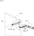
- Fig. 2 shows the support 2 and the fitting 4 separated from each other.
- the first fitting part 6 is to be fastened in or to a plate 5a-5e of the support 2.
- the first fitting part 6 has a mounting part 9, which can be inserted into a recess in the plate 5a and fixed to the plate 5a via at least one fastening device 10.
- the fastening device 10 can be realized according to various designs and can, for example, have at least one hole for the passage of a screw, at least one eccentric or at least one clamping screw.
- the fastening device 10 has at least one movable fastening element 10a, wherein by actuating the fastening element 10a by means of a tool at least one clamping part 31 ( Fig. 9 ) of the fastening device 10 can be frictionally connected to the plate 5a.
- the mounting part 9 is to be pre-assembled to the plate 5a via the fastening device 10.
- the mounting part 9 has a preferably pocket-shaped housing 11 into which a coupling part 12 of the first fitting part 6 can be inserted and releasably locked within the housing 11 via at least one locking device 13.
- the coupling part 12 of the first fitting part 6 is pivotally connected to the second fitting part 7 via at least one articulated lever 8a.
- the second fitting part 7 can be designed to be at least partially, preferably substantially completely, recessed into a recess of the pivot element 3. Alternatively, the second fitting part 7 can be arranged entirely outside a wall thickness of the pivot element 3 in an assembled state.
- the housing 11 of the mounting part 9 has a slot-shaped recess for receiving the coupling part 12.
- the housing 11 has a height extension (H) and a length extension (L), wherein the length extension (L) of the housing 11 can be at least three times, preferably at least six times, greater than the height extension (H).
- the coupling part 12 which is preferably essentially cuboid-shaped, has dimensions corresponding to the height extension (H) and the length extension (L), wherein the coupling part 12 can be received in an approximately form-fitting manner within the housing 11 of the mounting part 9.
- Fig. 3 shows the mounting part 9 and the coupling part 12 of the first fitting part 6 in a separated state from each other.
- the coupling part 12 can be releasably locked to the mounting part 9 by at least one locking device 13.
- the at least one locking device 13 has an ejection device 14, by means of which the coupling part 12 can be ejected, at least in sections, from the housing 11 of the mounting part 9 during unlocking.
- the coupling part 12 can be inserted into the housing 11 of the assembly part 9 in a joining direction (FR), wherein the coupling part 12 can be ejected by the ejection device 14 during unlocking, at least in sections, against the joining direction (FR).
- the housing 11 of the mounting part 9 can have an end face 18, wherein the coupling part 12 can be inserted into the housing 11 of the mounting part 9 during assembly essentially perpendicular to the end face 18.
- the end face 18 of the housing 11 runs essentially parallel to a front narrow side of the plate 5a of the carrier 2.
- the coupling part 12 can have a rear side 15, wherein the ejection device 14 acts on the rear side 15 of the coupling part 12 during the unlocking process, preferably being able to be placed against the rear side 15.
- the ejection device 14 can be placed against a recess of the coupling part 12 arranged on the rear side 15.
- At least one armature 20 is provided which can rotate about a rotational axis 19, wherein the armature 20 has a shaft and two arms projecting from the shaft.
- the spring element 16 engages a first arm of the armature 20, which Ejection lever 14a is arranged on a second arm of the armature 20 and the locking lever 13a is arranged on the shaft of the armature 20.
- Fig. 5 shows a continued insertion movement of the coupling part 12 into the mounting part 9 pre-assembled on the carrier 2.
- the coupling part 12 can have at least one lateral recess 17b, which engages with an engagement element 23 arranged on the mounting part 9 in
- the engagement element 23 can be designed, for example, as a projection, as a cylindrical bolt or as a rotatably mounted roller, wherein the axis of rotation of the roller runs essentially parallel to the vertical extent (H) of the mounting part 9.
- H vertical extent
- Fig. 6 shows that the recess 17b of the coupling part 12 can be brought into engagement with the engagement element 23 of the mounting part 9 by a slight movement of the coupling part 12 in the direction of the longitudinal extension (L).
- Fig. 7 shows the locked position between the coupling part 12 and the mounting part 9.
- the coupling part 12 was pressed further into the housing 11 of the mounting part 9, whereby the control element 22 (for example, a cylindrical pin) was moved out of a locking recess 24 of the control cam 21.
- the locking lever 13a is moved about the rotation axis 19 by the force of the relaxing spring element 16 and is engaged in the lateral recess 17a of the coupling part 12.
- the locking lever 13a of the locking device 13 and the ejection lever 14a of the ejection device 14 are formed together in one piece and are preferably prestressed by the same, single spring element 16.
- Fig. 8 shows the release of the lock between the coupling part 12 and the mounting part 9 and the ejection of the coupling part 12 from the housing 11 of the mounting part 9 in an ejection direction (AR).
- the release element 25a is pressed into the housing 11 of the mounting part 9 by means of a tool, whereby the control element 22 is moved along the control curve 21 against the force of the spring element 16 and the spring element 16 is tensioned.
- the locking lever 13a of the locking device 13 is also moved out of the recess 17a of the coupling part 12, and the ejection lever 14a of the ejection device 14 is tilted about the rotation axis 19.
- the control element 22 springs back into the detent recess 24 of the control cam 21, whereby the coupling part 12 can be ejected from the housing 11 of the mounting part 9 in the ejection direction (AR) by the ejection lever 14a and the force of the relaxing spring element 16.
- At least one guide 26 is provided for the linear guidance of the release element 25a, through which the release element 25a can be guided in a direction perpendicular to the end face 18.
- the coupling part 12 is inserted substantially perpendicular to an end face 18 of the housing 11 of the mounting part 9, preferably wherein the coupling part 12 is moved substantially parallel to the end face 18 of the housing 11 of the mounting part 9 shortly before reaching an end position in the housing 11.
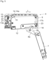
- Fig. 9 shows the mounting part 9 of the first fitting part 6 in an exploded view.
- the mounting part 9 has two interconnectable housing parts 9a, 9b, between which the locking device 13 with the locking lever 13a and the ejection device 14 are arranged.
- the armature 20 can be seen, on which the spring element 16 engages and on which the locking lever 13a and the ejection lever 14a are jointly formed.
- the mounting part 9 is to be fastened to a plate 5a-5e of the carrier 2 via at least one fastening device 10.
- the fastening device 10 can have a fastening element 10a and a clamping part 31 drivable by the fastening element 10a, by means of which the mounting part 9 can be fixed within a plate 5a-5e of the carrier 2.
Landscapes
- Engineering & Computer Science (AREA)
- Mechanical Engineering (AREA)
- Connection Of Plates (AREA)
- Hinges (AREA)
- Pivots And Pivotal Connections (AREA)
- Closing And Opening Devices For Wings, And Checks For Wings (AREA)
Claims (14)
- Ferrure (4) pour le montage mobile d'un élément pivotant (3), en particulier d'une pièce de meuble (3a), d'une porte ou d'une fenêtre, par rapport à un support (2) fixe, comprenant:- une première pièce de ferrure (6), laquelle est réalisée pour être fixée à une plaque (5a-5e) du support (2), de préférence orientée sensiblement horizontalement,- une deuxième pièce de ferrure (7) à fixer sur l'élément pivotant (3), dans laquelle la deuxième pièce de ferrure (7) est reliée de manière pivotante à la première pièce de ferrure (6),- dans laquelle la première pièce de ferrure (6) présente une pièce de montage (9) avec au moins un dispositif de fixation (10) par lequel la pièce de montage (9) peut être fixée sur la plaque (5a-5e) du support (2), et que la première pièce de ferrure (6) présente au moins une pièce d'accouplement (12) reliée de manière articulée à la deuxième pièce de ferrure (7), laquelle peut être reliée de manière détachable à la pièce de montage (9),- dans laquelle la pièce de montage (9) de la première pièce de ferrure (6) présente un boîtier (11), de préférence en forme de poche, dans laquelle la pièce d'accouplement (12) dans l'état relié à la pièce de montage (9) est reçue au moins par endroits, de préférence en majeure partie, à l'intérieur du boîtier (11) de la pièce de montage (9),- au moins un dispositif de verrouillage (13) par lequel la pièce d'accouplement (12) peut être déverrouillée de manière détachable avec la pièce de montage (9),- dans laquelle l'au moins un dispositif de verrouillage (13) comprend un dispositif d'éjection (14) par lequel la pièce d'accouplement (12) peut être éjectée au moins sur certaines parties du boîtier (11) de la pièce de montage (9) dans le cadre d'un déverrouillage,- dans laquelle un dispositif de desserrage (25) avec un élément de desserrage (25a) monté mobile est prévu pour le desserrage du verrouillage entre la pièce de montage (9) et la pièce d'accouplement (12).
- Ferrure (4) selon la revendication 1, caractérisée en ce que la pièce d'accouplement (12) peut être insérée dans un sens d'assemblage (FR) lors du montage dans le boîtier (11) de la pièce de montage (9), dans laquelle la pièce d'accouplement (12) peut être éjectée par le dispositif d'éjection (14) dans le sens opposé au sens d'assemblage (FR) dans le cadre du déverrouillage.
- Ferrure (4) selon la revendication 1 ou 2, caractérisée en ce que le boîtier (11) de la pièce de montage (9) présente une surface frontale (18), dans laquelle la pièce d'accouplement (12) peut être insérée lors du montage sensiblement perpendiculairement à la surface frontale (18) dans le boîtier (11) de la pièce de montage (9).
- Ferrure (4) selon l'une quelconque des revendications 1 à 3, caractérisée en ce que le boîtier (11) de la pièce de montage (9) présente une surface frontale (18), dans laquelle le verrouillage entre la pièce de montage (9) et la pièce d'accouplement (12) s'effectue dans une zone adjacente à la surface frontale (18).
- Ferrure (4) selon l'une quelconque des revendications 1 à 4, caractérisée en ce que la pièce d'accouplement (12) présente une face arrière (15), dans laquelle le dispositif d'éjection (14) agit dans le cadre du déverrouillage sur la face arrière (15) de la pièce d'accouplement (12), de préférence peut être appliqué sur la face arrière (15) de la pièce d'accouplement (12).
- Ferrure (4) selon l'une quelconque des revendications 1 à 5, caractérisée en ce que le dispositif de verrouillage (13) présente au moins un levier de verrouillage (13a) pivotant pour le verrouillage libérable de la pièce d'accouplement (12), de préférence dans laquelle l'au moins un levier de verrouillage (13a) présente- une position de verrouillage et une position de déverrouillage, dans laquelle l'au moins un levier de verrouillage (13a) pour le montage de la pièce d'accouplement (12) est disposé dans la position de déverrouillage, et/ou- est précontraint par au moins un élément ressort (16), de préférence un ressort hélicoïdal, de préférence dans laquelle l'au moins un levier de verrouillage (13a) peut être déplacé lors de l'insertion de la pièce d'accouplement (12) dans le boîtier (11) de la pièce de montage (9) à l'encontre d'une force de l'élément ressort (16) et peut être déverrouillé de manière libérable avec la pièce d'accouplement (12) lors d'un mouvement d'insertion continu du boîtier (11), et/ou- peut être verrouillé de manière détachable au moyen d'une came de commande (21) et d'un élément de commande (22) mobile le long de la came de commande (21), de préférence un boulon, et/ou- peut être verrouillé de manière détachable avec au moins un évidement (17a, 17b) de la pièce d'accouplement (12), et/ou- est disposé dans ou sur la pièce de montage (9) de la première pièce de ferrure (6).
- Ferrure (4) selon l'une quelconque des revendications 1 à 6, caractérisée en ce que le dispositif d'éjection (14) présente au moins un levier d'éjection (14a) pivotant pour l'éjection de la pièce d'accouplement (12), de préférence dans laquelle l'au moins un levier d'éjection (14a)- agit sur une face arrière (15) de la pièce d'accouplement (12) dans le cadre du déverrouillage, et/ou- est précontraint par au moins un élément ressort (16), et/ou- est relié d'une seule pièce à un levier de verrouillage (13a) du dispositif de verrouillage (13), et/ou- est disposé dans ou sur la pièce de montage (9) de la première pièce de ferrure (6).
- Ferrure (4) selon l'une quelconque des revendications 1 à 7, caractérisée en ce que le dispositif de verrouillage (13) présente au moins un levier de verrouillage (13a) pivotant pour le verrouillage libérable de la pièce d'accouplement (12) et que le dispositif d'éjection (14) présente au moins un levier d'éjection (14a) pour l'éjection de la pièce d'accouplement (12) hors du boîtier (11) de la pièce de montage (9), de préférence dans laquelle- l'au moins un levier de verrouillage (13a) et l'au moins un levier d'éjection (14a) sont reliés l'un à l'autre d'une seule pièce, et/ou- l'au moins un levier de verrouillage (13a) et l'au moins un levier d'éjection (14a) sont précontraints par un même élément ressort (16), et/ou- au moins une ancre (20) montée en rotation avec une tige et deux bras en saillie de la tige est prévue, dans laquelle un élément ressort (16) s'engage sur un premier bras de l'ancre (20), le levier d'éjection (14a) est disposé sur un deuxième bras de l'ancre (20) et le levier de verrouillage (13a) est disposé sur la tige de l'ancre (20), et/ou- l'au moins un levier de verrouillage (13a) et l'au moins un levier d'éjection (14a) sont disposés sur la pièce de montage (9) de la première pièce de ferrure (6).
- Ferrure (4) selon l'une quelconque des revendications 1 à 8, caractérisée en ce que l'élément de desserrage (25a)- est monté de manière à pouvoir coulisser linéairement, et/ou- peut être actionné à l'aide d'un outil et/ou- peut être déplacé à l'encontre d'une force d'un élément ressort (16) dans une position de desserrage libérant la pièce d'accouplement (12), et/ou- est mobile le long d'au moins un guidage (26), et/ou- peut être déplacé perpendiculairement à une surface frontale (18) de la pièce de montage (9) et/ou peut être actionné à partir d'une surface frontale (18) de la pièce de montage (9).
- Ferrure (4) selon l'une quelconque des revendications 1 à 9, caractérisée en ce que la pièce d'accouplement (12)- dans un état inséré dans le boîtier (11) de la pièce de montage (9) et lorsqu'un dispositif de verrouillage (13) se trouve dans une position de déverrouillage est reçue avec un jeu latéral à l'intérieur du boîtier (11) de la pièce de montage (9), et/ou- présente au moins une paroi latérale (27a) et le boîtier (11) de la pièce de montage (9) présente une paroi latérale (28) pour le guidage de l'au moins une paroi latérale (27a) de la pièce d'accouplement (12) lors du montage, de préférence dans laquelle l'au moins une paroi latérale (27a) de la pièce d'accouplement (12) et la paroi latérale (28) du boîtier (11) sont espacées l'une de l'autre dans une position verrouillée de la pièce d'accouplement (12), de préférence transversalement par rapport à un sens d'assemblage (FR) de la pièce d'accouplement (12), et/ou- présente deux parois latérales (27a, 27b) opposées, sur lesquelles est disposé respectivement au moins un évidement (17a, 17b) pour le verrouillage libérable de la pièce d'accouplement (12) avec le boîtier (11) de la pièce de montage (9), et/ou- présente au moins un évidement (17a, 17b) pour le verrouillage de la pièce d'accouplement (12) avec la pièce de montage (9), de préférence dans laquelle l'au moins un évidement (17a, 17b) est disposé de manière adjacente à une surface frontale (18) de la pièce d'accouplement (12), et/ou- est relié de manière pivotante à la deuxième pièce de ferrure (7) au moyen d'au moins un levier articulé (8a, 8b), de préférence au moins deux leviers articulés (8a, 8b), et/ou- présente au moins un dispositif de réglage (30a, 30b) par lequel une position de la pièce d'accouplement (12) est réglable par rapport à la pièce de montage (9), et/ou- présente une étendue en hauteur (H) et une étendue en longueur (L), dans laquelle l'étendue en longueur (L) est au moins trois fois, de préférence au moins six fois, supérieure à l'étendue en hauteur (H).
- Ferrure (4) selon l'une quelconque des revendications 1 à 10, caractérisée en ce que le boîtier (11) de la pièce de montage (9)- est réalisé de sorte que le boîtier (11) puisse être intégré sensiblement entièrement à l'intérieur de la plaque (5a-5e) du support (2), et/ou- - présente une étendue en hauteur (H) et une étendue en longueur (L), dans laquelle l'étendue en longueur (L) du boîtier (11) de la pièce de montage (9) est au moins trois fois, de préférence au moins six fois, supérieure à l'étendue en hauteur (H), et/ou- présente le dispositif de verrouillage (13) et le dispositif d'éjection (14).
- Procédé pour le montage mobile d'un élément pivotant (3), en particulier d'une pièce de meuble (3a), d'une porte ou d'une fenêtre, sur un support (2) fixe au moyen d'au moins une ferrure (4) selon l'une quelconque des revendications 1 à 11, comprenant les étapes de procédé suivantes:- la pièce de montage (9) de la première pièce de ferrure (6) est fixée sur ou dans une plaque (5a-5e) du support (2), de préférence orientée sensiblement horizontalement,- la deuxième pièce de ferrure (7) est fixée sur l'élément pivotant (3),- la pièce d'accouplement (12) reliée de manière articulée à la deuxième pièce de ferrure (7) est introduite dans le boîtier (11), de préférence en forme de poche, de la pièce de montage (9) de la première pièce de ferrure (6),- la pièce d'accouplement (12) est verrouillée de manière détachable avec le boîtier (11) de la pièce de montage (9) au moyen du dispositif de verrouillage (13), et- la pièce d'accouplement (12) est éjectée au moins sur certaines parties du boîtier (11) de la pièce de montage (9) au moyen du dispositif d'éjection (14) dans le cadre d'un déverrouillage.
- Procédé selon la revendication 12, dans lequel la pièce d'accouplement (12) est introduite sensiblement perpendiculairement à une surface frontale (18) du boîtier (11) de la pièce de montage (9).
- Procédé selon la revendication 13, dans lequel la pièce d'accouplement (12) est déplacée peu avant d'atteindre une position finale dans le boîtier (11) sensiblement parallèlement à la surface frontale (18) du boîtier (11) de la pièce de montage (9).
Priority Applications (1)
| Application Number | Priority Date | Filing Date | Title |
|---|---|---|---|
| EP25170611.5A EP4560099A3 (fr) | 2021-11-26 | 2022-10-13 | Ferrure pour le montage mobile d'un élément pivotant par rapport à un support fixe |
Applications Claiming Priority (2)
| Application Number | Priority Date | Filing Date | Title |
|---|---|---|---|
| ATA50950/2021A AT525172B1 (de) | 2021-11-26 | 2021-11-26 | Beschlag zur bewegbaren Lagerung eines Schwenkelementes relativ zu einem stationären Träger |
| PCT/AT2022/060354 WO2023092160A1 (fr) | 2021-11-26 | 2022-10-13 | Raccord pour le montage mobile d'un élément pivot par rapport à un support fixe |
Related Child Applications (1)
| Application Number | Title | Priority Date | Filing Date |
|---|---|---|---|
| EP25170611.5A Division EP4560099A3 (fr) | 2021-11-26 | 2022-10-13 | Ferrure pour le montage mobile d'un élément pivotant par rapport à un support fixe |
Publications (2)
| Publication Number | Publication Date |
|---|---|
| EP4437210A1 EP4437210A1 (fr) | 2024-10-02 |
| EP4437210B1 true EP4437210B1 (fr) | 2025-04-16 |
Family
ID=83995330
Family Applications (2)
| Application Number | Title | Priority Date | Filing Date |
|---|---|---|---|
| EP22793628.3A Active EP4437210B1 (fr) | 2021-11-26 | 2022-10-13 | Raccord pour le montage mobile d'un élément pivot par rapport à un support fixe |
| EP25170611.5A Pending EP4560099A3 (fr) | 2021-11-26 | 2022-10-13 | Ferrure pour le montage mobile d'un élément pivotant par rapport à un support fixe |
Family Applications After (1)
| Application Number | Title | Priority Date | Filing Date |
|---|---|---|---|
| EP25170611.5A Pending EP4560099A3 (fr) | 2021-11-26 | 2022-10-13 | Ferrure pour le montage mobile d'un élément pivotant par rapport à un support fixe |
Country Status (7)
| Country | Link |
|---|---|
| US (1) | US12497810B2 (fr) |
| EP (2) | EP4437210B1 (fr) |
| JP (1) | JP7721811B2 (fr) |
| CN (1) | CN118302589A (fr) |
| AT (1) | AT525172B1 (fr) |
| ES (1) | ES3031424T3 (fr) |
| WO (1) | WO2023092160A1 (fr) |
Families Citing this family (2)
| Publication number | Priority date | Publication date | Assignee | Title |
|---|---|---|---|---|
| JP1752599S (ja) | 2022-07-25 | 2023-09-07 | 家具用部品用部材 | |
| USD1056697S1 (en) * | 2022-07-25 | 2025-01-07 | Julius Blum Gmbh | Furniture fitting |
Family Cites Families (16)
| Publication number | Priority date | Publication date | Assignee | Title |
|---|---|---|---|---|
| DE2723850C2 (de) * | 1977-05-26 | 1986-08-28 | Richard Heinze GmbH & Co KG, 4905 Spenge | Möbelscharnier |
| JPS57199676A (en) | 1981-06-03 | 1982-12-07 | Canon Inc | Nonimpaction type printer |
| JPS5912375Y2 (ja) * | 1981-06-15 | 1984-04-14 | 株式会社中尾製作所 | 扉を自在に着脱するための蝶番 |
| DE3525279A1 (de) * | 1985-07-16 | 1987-01-29 | Lautenschlaeger Kg Karl | Moebelscharnier |
| JPS6268981A (ja) * | 1985-09-18 | 1987-03-30 | 余合住金産業株式会社 | 蝶番 |
| JP2726526B2 (ja) * | 1989-11-30 | 1998-03-11 | 株式会社ムラコシ精工 | ヒンジ |
| DE29703227U1 (de) * | 1997-02-24 | 1998-07-02 | Prämeta Gesellschaft für Präzisionsmetall- und Kunststofferzeugnisse mbH & Co KG, 51107 Köln | Schnellmontagetopf für Möbelscharniere |
| JP4846446B2 (ja) * | 2006-05-19 | 2011-12-28 | スガツネ工業株式会社 | ヒンジ装置 |
| US7552511B2 (en) * | 2006-07-28 | 2009-06-30 | Creative Research & Development, Inc. | Adjustable hinge |
| US8234753B2 (en) * | 2008-10-24 | 2012-08-07 | L-3 Communications Integrated Systems L.P. | Cook hinge |
| CN104427804B (zh) * | 2013-09-05 | 2017-06-13 | 纬创资通股份有限公司 | 门板装置及储存设备 |
| SMT202100097T1 (it) * | 2015-04-30 | 2021-03-15 | Salice Arturo Spa | Cerniera decelerata per mobili |
| IT201700062317A1 (it) * | 2017-06-07 | 2018-12-07 | Effegi Brevetti Srl | Cerniera per mobili con dispositivo di regolazione della forza di chiusura |
| DE202018102088U1 (de) * | 2018-04-17 | 2019-07-18 | Grass Gmbh | Vorrichtung zur Bewegung eines Möbelteils und Möbel |
| AT521436B1 (de) | 2018-07-03 | 2025-07-15 | Blum Gmbh Julius | Möbelbeschlag |
| AT521437B1 (de) * | 2018-07-03 | 2025-06-15 | Blum Gmbh Julius | Möbelbeschlag |
-
2021
- 2021-11-26 AT ATA50950/2021A patent/AT525172B1/de active
-
2022
- 2022-10-13 EP EP22793628.3A patent/EP4437210B1/fr active Active
- 2022-10-13 ES ES22793628T patent/ES3031424T3/es active Active
- 2022-10-13 EP EP25170611.5A patent/EP4560099A3/fr active Pending
- 2022-10-13 CN CN202280077711.1A patent/CN118302589A/zh active Pending
- 2022-10-13 WO PCT/AT2022/060354 patent/WO2023092160A1/fr not_active Ceased
- 2022-10-13 JP JP2024531381A patent/JP7721811B2/ja active Active
-
2024
- 2024-04-26 US US18/647,765 patent/US12497810B2/en active Active
Also Published As
| Publication number | Publication date |
|---|---|
| AT525172A4 (de) | 2023-01-15 |
| JP2024540662A (ja) | 2024-10-31 |
| US20240271473A1 (en) | 2024-08-15 |
| EP4560099A2 (fr) | 2025-05-28 |
| CN118302589A (zh) | 2024-07-05 |
| EP4437210A1 (fr) | 2024-10-02 |
| AT525172B1 (de) | 2023-01-15 |
| ES3031424T3 (en) | 2025-07-08 |
| EP4560099A3 (fr) | 2025-08-06 |
| JP7721811B2 (ja) | 2025-08-12 |
| WO2023092160A1 (fr) | 2023-06-01 |
| US12497810B2 (en) | 2025-12-16 |
Similar Documents
| Publication | Publication Date | Title |
|---|---|---|
| AT507577B1 (de) | Möbelbeschlag zum lösbaren verbinden zweier möbelteile | |
| EP3818224B1 (fr) | Ferrure pour meuble | |
| EP4437210B1 (fr) | Raccord pour le montage mobile d'un élément pivot par rapport à un support fixe | |
| EP4437207B1 (fr) | Raccord pour le montage mobile d'un élément pivotant par rapport à un support fixe | |
| DE69020604T2 (de) | Verborgene Vorrichtung zur Wandmontage eines Wandmöbelelementes. | |
| EP1785062A1 (fr) | Guide telescopique destiné à des tiroirs et le tiroir | |
| WO2007068019A1 (fr) | Meuble presentant au moins des premiere et deuxieme parties de meuble | |
| EP2250929A1 (fr) | Elément d'armoire doté d'un élément de sortie rétractable | |
| EP3899289A1 (fr) | Dispositif d'entraînement de meuble | |
| WO2022048827A1 (fr) | Charnière destinée à relier de manière amovible et pivotante une aile à une partie de base | |
| DE102005034833A1 (de) | Verschluß mit Ratschenklinke | |
| AT402794B (de) | Skibindung mit einer arretiervorrichtung für vorder- und/oder fersenbacken | |
| EP3758553B1 (fr) | Meuble ou appareil ménager et procédé de montage d'une unité fonctionnelle d'un élément de tiroir dans un meuble ou un appareil ménager | |
| DE4307911A1 (de) | Rollschubkastenregal | |
| EP1297765B1 (fr) | Dispositif de montage et de démontage sans outil d'une façade de tiroir de meubles | |
| EP3487359B1 (fr) | Dispositif d'éjection pour un élément de meuble mobile et meuble | |
| DE202009016669U1 (de) | Möbel, Möbelteil und Vorrichtung zur Verbindung eines Frontbauteils eines Möbelteils | |
| DE4239599C2 (de) | Handbetätigte Verschließvorrichtung für Wagenkästen und Container | |
| EP1567032A1 (fr) | Armature pour rallonge d'armoire | |
| DE3243865C2 (de) | Türscharnier für Haushaltgeräte | |
| EP1512817B1 (fr) | Ferrure pour portes, fenêtres ou similaires | |
| EP4568543B1 (fr) | Ferrure de meuble ou de construction | |
| AT526823B1 (de) | Ausziehführung | |
| EP0199270A2 (fr) | Dispositif pour maintenir une porte ou une fenêtre entrouverte dans au moins une position | |
| EP4133974B1 (fr) | Dispositif de déplacement d'une partie mobile de meuble dans une direction d'ouverture |
Legal Events
| Date | Code | Title | Description |
|---|---|---|---|
| STAA | Information on the status of an ep patent application or granted ep patent |
Free format text: STATUS: UNKNOWN |
|
| STAA | Information on the status of an ep patent application or granted ep patent |
Free format text: STATUS: THE INTERNATIONAL PUBLICATION HAS BEEN MADE |
|
| PUAI | Public reference made under article 153(3) epc to a published international application that has entered the european phase |
Free format text: ORIGINAL CODE: 0009012 |
|
| STAA | Information on the status of an ep patent application or granted ep patent |
Free format text: STATUS: REQUEST FOR EXAMINATION WAS MADE |
|
| 17P | Request for examination filed |
Effective date: 20240408 |
|
| AK | Designated contracting states |
Kind code of ref document: A1 Designated state(s): AL AT BE BG CH CY CZ DE DK EE ES FI FR GB GR HR HU IE IS IT LI LT LU LV MC ME MK MT NL NO PL PT RO RS SE SI SK SM TR |
|
| GRAP | Despatch of communication of intention to grant a patent |
Free format text: ORIGINAL CODE: EPIDOSNIGR1 |
|
| STAA | Information on the status of an ep patent application or granted ep patent |
Free format text: STATUS: GRANT OF PATENT IS INTENDED |
|
| DAV | Request for validation of the european patent (deleted) | ||
| DAX | Request for extension of the european patent (deleted) | ||
| GRAS | Grant fee paid |
Free format text: ORIGINAL CODE: EPIDOSNIGR3 |
|
| GRAA | (expected) grant |
Free format text: ORIGINAL CODE: 0009210 |
|
| STAA | Information on the status of an ep patent application or granted ep patent |
Free format text: STATUS: THE PATENT HAS BEEN GRANTED |
|
| INTG | Intention to grant announced |
Effective date: 20250217 |
|
| AK | Designated contracting states |
Kind code of ref document: B1 Designated state(s): AL AT BE BG CH CY CZ DE DK EE ES FI FR GB GR HR HU IE IS IT LI LT LU LV MC ME MK MT NL NO PL PT RO RS SE SI SK SM TR |
|
| REG | Reference to a national code |
Ref country code: GB Ref legal event code: FG4D Free format text: NOT ENGLISH |
|
| REG | Reference to a national code |
Ref country code: CH Ref legal event code: EP Ref country code: DE Ref legal event code: R096 Ref document number: 502022003621 Country of ref document: DE |
|
| REG | Reference to a national code |
Ref country code: IE Ref legal event code: FG4D Free format text: LANGUAGE OF EP DOCUMENT: GERMAN |
|
| REG | Reference to a national code |
Ref country code: ES Ref legal event code: FG2A Ref document number: 3031424 Country of ref document: ES Kind code of ref document: T3 Effective date: 20250708 |
|
| REG | Reference to a national code |
Ref country code: NL Ref legal event code: MP Effective date: 20250416 |
|
| PG25 | Lapsed in a contracting state [announced via postgrant information from national office to epo] |
Ref country code: NL Free format text: LAPSE BECAUSE OF FAILURE TO SUBMIT A TRANSLATION OF THE DESCRIPTION OR TO PAY THE FEE WITHIN THE PRESCRIBED TIME-LIMIT Effective date: 20250416 |
|
| PG25 | Lapsed in a contracting state [announced via postgrant information from national office to epo] |
Ref country code: PT Free format text: LAPSE BECAUSE OF FAILURE TO SUBMIT A TRANSLATION OF THE DESCRIPTION OR TO PAY THE FEE WITHIN THE PRESCRIBED TIME-LIMIT Effective date: 20250818 Ref country code: FI Free format text: LAPSE BECAUSE OF FAILURE TO SUBMIT A TRANSLATION OF THE DESCRIPTION OR TO PAY THE FEE WITHIN THE PRESCRIBED TIME-LIMIT Effective date: 20250416 |
|
| REG | Reference to a national code |
Ref country code: LT Ref legal event code: MG9D |
|
| PG25 | Lapsed in a contracting state [announced via postgrant information from national office to epo] |
Ref country code: NO Free format text: LAPSE BECAUSE OF FAILURE TO SUBMIT A TRANSLATION OF THE DESCRIPTION OR TO PAY THE FEE WITHIN THE PRESCRIBED TIME-LIMIT Effective date: 20250716 Ref country code: GR Free format text: LAPSE BECAUSE OF FAILURE TO SUBMIT A TRANSLATION OF THE DESCRIPTION OR TO PAY THE FEE WITHIN THE PRESCRIBED TIME-LIMIT Effective date: 20250717 |
|
| PG25 | Lapsed in a contracting state [announced via postgrant information from national office to epo] |
Ref country code: PL Free format text: LAPSE BECAUSE OF FAILURE TO SUBMIT A TRANSLATION OF THE DESCRIPTION OR TO PAY THE FEE WITHIN THE PRESCRIBED TIME-LIMIT Effective date: 20250416 |
|
| PGFP | Annual fee paid to national office [announced via postgrant information from national office to epo] |
Ref country code: TR Payment date: 20250923 Year of fee payment: 4 |
|
| PG25 | Lapsed in a contracting state [announced via postgrant information from national office to epo] |
Ref country code: BG Free format text: LAPSE BECAUSE OF FAILURE TO SUBMIT A TRANSLATION OF THE DESCRIPTION OR TO PAY THE FEE WITHIN THE PRESCRIBED TIME-LIMIT Effective date: 20250416 |
|
| PG25 | Lapsed in a contracting state [announced via postgrant information from national office to epo] |
Ref country code: HR Free format text: LAPSE BECAUSE OF FAILURE TO SUBMIT A TRANSLATION OF THE DESCRIPTION OR TO PAY THE FEE WITHIN THE PRESCRIBED TIME-LIMIT Effective date: 20250416 |
|
| PG25 | Lapsed in a contracting state [announced via postgrant information from national office to epo] |
Ref country code: RS Free format text: LAPSE BECAUSE OF FAILURE TO SUBMIT A TRANSLATION OF THE DESCRIPTION OR TO PAY THE FEE WITHIN THE PRESCRIBED TIME-LIMIT Effective date: 20250716 |
|
| PG25 | Lapsed in a contracting state [announced via postgrant information from national office to epo] |
Ref country code: IS Free format text: LAPSE BECAUSE OF FAILURE TO SUBMIT A TRANSLATION OF THE DESCRIPTION OR TO PAY THE FEE WITHIN THE PRESCRIBED TIME-LIMIT Effective date: 20250816 |
|
| PG25 | Lapsed in a contracting state [announced via postgrant information from national office to epo] |
Ref country code: LV Free format text: LAPSE BECAUSE OF FAILURE TO SUBMIT A TRANSLATION OF THE DESCRIPTION OR TO PAY THE FEE WITHIN THE PRESCRIBED TIME-LIMIT Effective date: 20250416 |
|
| PGFP | Annual fee paid to national office [announced via postgrant information from national office to epo] |
Ref country code: DE Payment date: 20251028 Year of fee payment: 4 |
|
| PG25 | Lapsed in a contracting state [announced via postgrant information from national office to epo] |
Ref country code: SM Free format text: LAPSE BECAUSE OF FAILURE TO SUBMIT A TRANSLATION OF THE DESCRIPTION OR TO PAY THE FEE WITHIN THE PRESCRIBED TIME-LIMIT Effective date: 20250416 Ref country code: DK Free format text: LAPSE BECAUSE OF FAILURE TO SUBMIT A TRANSLATION OF THE DESCRIPTION OR TO PAY THE FEE WITHIN THE PRESCRIBED TIME-LIMIT Effective date: 20250416 |
|
| PGFP | Annual fee paid to national office [announced via postgrant information from national office to epo] |
Ref country code: AT Payment date: 20260113 Year of fee payment: 4 |
|
| PGFP | Annual fee paid to national office [announced via postgrant information from national office to epo] |
Ref country code: IT Payment date: 20251031 Year of fee payment: 4 |
|
| REG | Reference to a national code |
Ref country code: DE Ref legal event code: R097 Ref document number: 502022003621 Country of ref document: DE |
|
| PG25 | Lapsed in a contracting state [announced via postgrant information from national office to epo] |
Ref country code: CZ Free format text: LAPSE BECAUSE OF FAILURE TO SUBMIT A TRANSLATION OF THE DESCRIPTION OR TO PAY THE FEE WITHIN THE PRESCRIBED TIME-LIMIT Effective date: 20250416 |
|
| PG25 | Lapsed in a contracting state [announced via postgrant information from national office to epo] |
Ref country code: EE Free format text: LAPSE BECAUSE OF FAILURE TO SUBMIT A TRANSLATION OF THE DESCRIPTION OR TO PAY THE FEE WITHIN THE PRESCRIBED TIME-LIMIT Effective date: 20250416 |
|
| PG25 | Lapsed in a contracting state [announced via postgrant information from national office to epo] |
Ref country code: SK Free format text: LAPSE BECAUSE OF FAILURE TO SUBMIT A TRANSLATION OF THE DESCRIPTION OR TO PAY THE FEE WITHIN THE PRESCRIBED TIME-LIMIT Effective date: 20250416 |
|
| PGFP | Annual fee paid to national office [announced via postgrant information from national office to epo] |
Ref country code: ES Payment date: 20251118 Year of fee payment: 4 |
|
| PLBE | No opposition filed within time limit |
Free format text: ORIGINAL CODE: 0009261 |
|
| STAA | Information on the status of an ep patent application or granted ep patent |
Free format text: STATUS: NO OPPOSITION FILED WITHIN TIME LIMIT |
|
| REG | Reference to a national code |
Ref country code: CH Ref legal event code: L10 Free format text: ST27 STATUS EVENT CODE: U-0-0-L10-L00 (AS PROVIDED BY THE NATIONAL OFFICE) Effective date: 20260225 |
|
| PG25 | Lapsed in a contracting state [announced via postgrant information from national office to epo] |
Ref country code: RO Free format text: LAPSE BECAUSE OF FAILURE TO SUBMIT A TRANSLATION OF THE DESCRIPTION OR TO PAY THE FEE WITHIN THE PRESCRIBED TIME-LIMIT Effective date: 20250416 |
|
| 26N | No opposition filed |
Effective date: 20260119 |